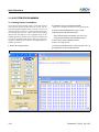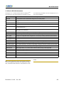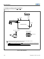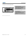
1
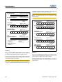
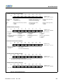
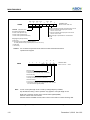
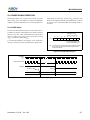
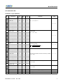
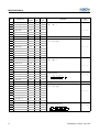
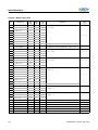
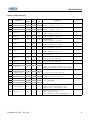
MC81F8816/8616
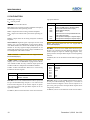
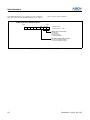
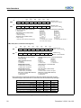
ASIMR
R/W
7
R/W
6
R/W
5
TXM
RXM
PS1
-
R/W
4
3
PS0 BTCL
R/W
2
SL
R/W
1
0
ISRM
-
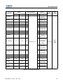
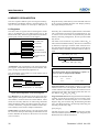
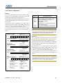
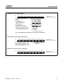
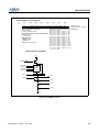
ADDRESS: 0B8H
INITIAL VALUE: 0000 -00-B
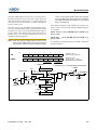
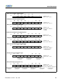
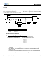
Receive Completion Interrrupt Control When Error Occurs
0: Receive completion interrupt request is issued
when an error occured
1: Receive completion interrupt request is not issued
when an error occured
TXM RXM (Operation mode)
00: Operation stop(R12/R13)
01: UART mode (Receive only)
10: UART mode (Transmit only)
Stop Bit Length for Specification for Transmit Data
11: UART mode (Transmit and receive)
0: 1 bit
1: 2 bit
PS [1:0] (Parity Bit Specification)
00: No Parity
01: Zero Parity always added during transmission.
No Parity detection during reception(Parity errors do not occur)
10: Odd Parity
11: Even Parity
Caution : Do not switch the operation mode until the current serial transmit/receive
operation has stopped.
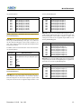
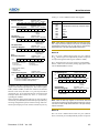
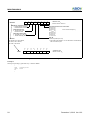
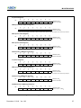
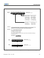
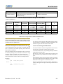
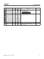
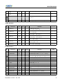
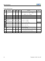
ASISR
7
6
5
4
-
-
-
-
3
BTCL
-
R
2
R
1
R
0
PE
FE
OVE
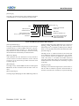
ADDRESS: 0B9H
INITIAL VALUE: ------000B
Parity Error Flag
0: No parity error
1: Parity error (Received data parity not matched)
Frame Error Flag
0: No Frame error
1: Framing error(Note1) (stop bit not detected)
Overrun Error Flag
0: No Overrun Error(Note2)
1: Next receive operation was completed before data was read
from receive buffer register (RXBR)
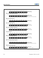
Note : 1. Even if a stop bit length is set to 2 bits by setting bit2(SL0) in ASIMR,
stop bit detection during a recive operation only applies to a stop bit length of 1bit.
2. Be sure to read the contents of the receive buffer register(RXBR)
when an overrun error has occurred.
Until the contents of RXBR are read, futher overrun errors will occur when receiving data.
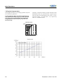
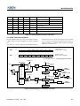
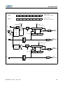
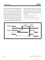
Figure 21-1 Asynchronous Serial Interface Mode & Status Register
112
December 3, 2012 Ver 1.03