1
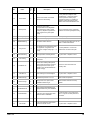
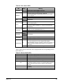
Alarm Descriptions
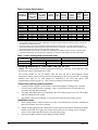
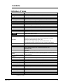
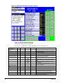
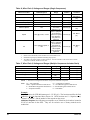
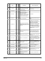
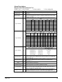
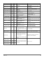
Table 35, Alarm Descriptions (LF 2.0
NOTE: Type, 1=Auto-resettable
2=Non-resettable
Alarm
Type
Analog In Loss
1
Bipolar Conflict
2
Dig In ConflictA
2
3=User-configurable
Description
An analog input is configured for alarm on signal loss and signal loss has
occurred.
Parameter 190 (Direction Mode) is set to Bipolar or Reverse Dis and one of more
of the following digital input functions is configured: Fwd/Rev, Run Fwd, Run Rev,
Jog Fwd, or Jog Rev.
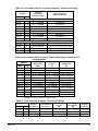
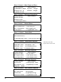
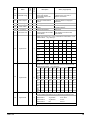
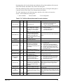
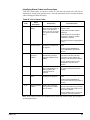
Digital input functions are in conflict. Combinations marked with a will cause an
alarm.
Acc2/
Jog
Jog
Fwd/R
Accel2 Cecel2
Jog
Dec2
Fwd
Rev
ev
Acc2/Dec2
x
x
Accel2
x
Cecel2
x
Jog
x
Jog Fwd
x
Jog Rev
x
x
X
x
Fwd/Rev
x
x
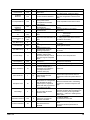
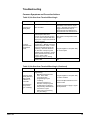
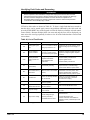
Digital input functions are in conflict. Combinations marked with a will x cause an
alarm.
Stop
Run
Run
Jog
Jog
Fwd/
Start
Jog
Run
-CF
Fwd
Rev
Fwd Rev
Rev
Start
x
x
x
x
x
Stop-CF
Dig In ConflictB
2
Run
x
Run Fwd
x
x
x
x
Run Rev
x
x
x
x
Jog Fwd
x
x
Jog Rev
x
x
x
Jog
Fwd/Rev
Dig In ConflictC
2
Drive OL Level 1
1
Drive OL Level 2
1
Flux Amps Ref
Rang
2
IntDBRes OvrHeat
1
IR Volts Range
2
MaxFreq Conflict
2
x
x
x
x
x
x
x
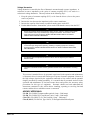
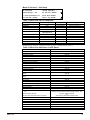
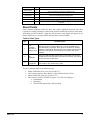
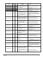
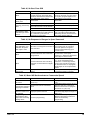
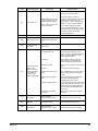
More than one physical input has been configured to the same input function.
Multiple configurations are not allowed for the following input functions:
Bus Regulation Mode
Forward/Reverse
Run Reverse
B
Speed Select 1
Jog Forward
Acc2 / Dec2
Speed Select 2
Jog Reverse
Accel 2
Speed Select 3
OIM Control
Decel 2
Run Forward
Stop Mode B
Run
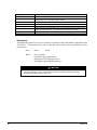
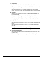
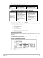
The calculated IGBT temperature requires a reduction in PWM carrier frequency.
If Drive OL Mode (150) is disabled and the load is not reduced, an overload fault
will eventually occur.
The calculated IGBT temperature requires a reduction in Current Limit. If Drive OL
Mode (150) is disabled and the load is not reduced, an overload fault will
eventually occur.
Result of autotune procedure (61).
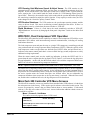
The drive has temporarily disabled the dynamic braking regulator because the
resistor temperature has exceeded a predetermined value.
The drive autotuning default is Calculate and the value calculated for IR Drop
Volts is not in the range of acceptable values. This alarm should clear when all
motor nameplate data is properly entered.
The sum of Maximum Speed (82) and Overspeed Limit (83) exceeds Maximum
Freq (55). Raise Maximum Freq (55) or lower Maximum Speed (82) and/or
Overspeed Limit (83) so that the sum is less than or equal to Maximum Freq (55).
Continued next page.
IOMM 1159
76