1
MIMO 2x2 Wireless Outdoor Access Point System User Manual R2
Concurrent Dual Radio 300Mbps WiFi
High Power Outdoor System
User Manual
January, 2015
1
MIMO 2x2 Wireless Outdoor Access Point System User Manual R2
Revision History
Date
Notes
July, 2014
Firmware v5.4.2
October,2014
Firmware v5.5.0 (memory size increase)
January, 2015
Firmware v5.6.1 (user isolation for 2.4GHz & 5GHz AP modes)
2
MIMO 2x2 Wireless Outdoor Access Point System User Manual R2
Introduction
The MIMO 2x2 Wireless Outdoor System (“outdoor unit” in the following paragraphs) consists of
two concurrent running radios, one at 5GHz supporting 802.11a/n standard, and the other at 2.4GHz for
802.11b/g/n features. This outdoor AP supports Point-to-Point and Point to Multipoint communication,
that the data rate is up to 150Mbps in HT-20 mode, or to 300 Mbps in HT-40 mode. The 5GHz Bridge
function is most suitable for enterprises, campus or off-site locations that require LAN or Internet access
without the availability of wired networks to extend network coverage up to 35Km.; and the 802.11 b/g/n
radio is mainly for Access Point application to provide local wireless access to the Internet, while 5GHz
also support Access Point mode.
The outdoor unit offers different encryption mechanisms including WEP, and AES to ensure the
communication security. For APs / Bridges connections, the MAC address authentication mechanism is
provided.
The outdoor unit is designed for the outdoor environment and it is weatherproofed against the
most stringent condition. For further protection, the bridge and Power over Ethernet adapter are all with
the built-in lightning protectors.
Its weatherproofed enclosure includes brackets for attaching to a wall, pole, radio mast, or tower
structure. The unit powered through its Ethernet cable connection from a power injector module that
installed indoors. The wireless bridge system offers a fast, reliable, and cost-effective solution
forconnectivity between remote Ethernet wired LANs or to provide Internet access to an isolated site.
The system is also easy to install and operate, ideal for situations where a wired link may be difficult or
expensive to deploy.
Key Features:
2x2 MIMO for both 5GHz (802.11n/a) and 2.4GHz (802.11n/b/g) Radios Platform
High speed Wire and Wireless connectivity
300Mbps 802.11n/a Backhaul and AP functions, 802.11n/b/g AP function
IP68 rated enclosure for dust and water protection
Wide operating temperature: -40oC to +60oC
Built-In lightning protection circuits
3
MIMO 2x2 Wireless Outdoor Access Point System User Manual R2
Manual Conventions
Bold
Italic
Courier
Bold type within paragraph text indicates commands, files names, directory
names, paths, output, or returned values.
Within commands, italics indicate a variable that the user must specify.
Titles of manuals or other published documents are also set in italics.
The courier font indicates output or display.
|
Within commands, items enclosed in square brackets are optional
parameters or values that the user can choose to specify or omit.
Within commands, item enclosed in braces are options from which the user
must choose.
Within commands, the vertical bar separates options.
…
An ellipsis indicates a repetition of preceding parameter.
>
The right angle bracket separates successive menu selection.
[]
{}
NOTE: This message denotes neutral or positive information that calls out important points to the text. A
note provides information that applies only in special cases.
Caution: Cautions call special attention to hazards that can cause system damage or data
corruption, to a lesser degree than warnings.
Warnings: Warnings call special attention to hazards that can cause system damage, data
corruption, personal injury, or death.
4
MIMO 2x2 Wireless Outdoor Access Point System User Manual R2
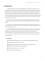
1. MIMO 2x2 Wireless Outdoor Access Point System Hardware Feature
1.1 Hardware Outline (ALINK-A300n)
5
MIMO 2x2 Wireless Outdoor Access Point System User Manual R2
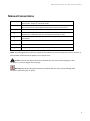
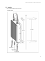
1.2 Hardware Outline (APRO-A300n)
6
MIMO 2x2 Wireless Outdoor Access Point System User Manual R2
Product Features
Range — the outdoor unit has been refined and optimized for long range application, up to
35Km.
Temperature — the outdoor unit was tested for normal operation in the ambient temperatures
from -40°C to 60°C. Operating in temperatures outside of this range may cause the unit
malfunctioned.
Wind Velocity— the outdoor unit can operate in winds up to 90mph and survive higher wind
speeds up to 125mph. You must consider the known maximum wind velocity and direction at
the site and be sure that any supporting structure, such as a pole, mast, or tower, built to
withstand this force.
Lightning — the outdoor unit includes lightning protection circuits inside. However, you should
make sure that the unit, any supporting structure, and cables are all properly grounded.
Additional protection using lightning rods, lightning arrestors, or surge suppressors may also
employed.
Rain — the weather plays one of major matters to the antenna performance for the wireless
communication. The raining day, the lightning day, the cloudy day, or the windy day will make a
quite big impact to both side antennas over the communication results. It will also affect the
communication quality. The outdoor unit is a weatherproofed outdoor unit, which can operate
in extremely weather environment. You may need to use the sealing tape around the external
antenna port connectors for extra protection. If moisture enters the connector, it may cause
degradation in performance or even a complete failure of the link.
Feature Highlight
5GHz 802.11a/n based Point-to-Point Bridge and access point mode
5GHz 802.11a/n based Point-to-Multipoint Bridge (up to 8 links) mode
2.4GHz 802.11b/g/n based high capacity access point mode
7
MIMO 2x2 Wireless Outdoor Access Point System User Manual R2
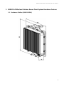
1.3 Interface
1.3.1 External Antenna Connection:
ALINK-A300n
8
MIMO 2x2 Wireless Outdoor Access Point System User Manual R2
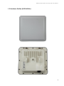
1.3.2 Hardware Installation Guide :
APRO-A300n
9
MIMO 2x2 Wireless Outdoor Access Point System User Manual R2
10
MIMO 2x2 Wireless Outdoor Access Point System User Manual R2
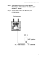
1.3.3
Power over Ethernet (PoE) & Cable Connection
PoE Ethernet Cable
connects to
Output port and
link to Outdoor
Unit
1.3.4
Ethernet cable
connects to Input
port and link to host
PC or LAN Device
(ex. Switch or Hub)
Grounding
1) Proper grounding is always recommended for the safety consideration.
11
MIMO 2x2 Wireless Outdoor Access Point System User Manual R2
1.4 Product Warranty
This product warranted against defects in materials and workmanship for a period of one year from
the date of shipment. If the customer wants to have or extend longer warranty period, please
contact the sales for extended warranty. During the warranty period, the defective product will be
repaired or to be replaced.
1.5 Warranty Limitation
The foregoing warranty shall not apply to defects resulting from improper or inadequate
maintenance by buyers, buyer-supplied software, interfacing, unauthorized modification,
inappropriately use, operation out of the product environment specifications, or improper site
preparation and maintenance.
1.6 System Requirement
Windows 2000, XP, Vista Home Basic or Windows 7, Windows 8
Microsoft Internet Explorer 5.5 or above versions and Google Chrome
1.7 Feature Summary
Provide the Ethernet to Wireless LAN Bridge, or the Ethernet to Wireless LAN Access Point, fully
IEEE 802.3 compatible Ethernet interface
Support 10/100/1000 Base-T Ethernet interface
The operating mode is IEEE 802.11a/n & 802.11b/g/n infrastructure for the outdoor unit
The dynamic data rate switching among the standards of 802.11a, 802.11b, 802.11g, 802.11n
HT 20, and 802.11n HT40- and 802.11n HT 40+ are provided by Atheros chipset. The auto
fallback feature of data rate capability optimizes the reliability, throughput and transmission
range
Using Web UI to upgrade the firmware
12
MIMO 2x2 Wireless Outdoor Access Point System User Manual R2
2. Getting Started
2.1
Setup Local Area Connection on your PC
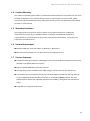
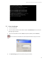
2.1.1 Start Network Configuration on your PC
1) Click Start > All Programs > Accessories > Communications > Network Connections
2) Right click on the Local Area Connection and select Properties
13
MIMO 2x2 Wireless Outdoor Access Point System User Manual R2
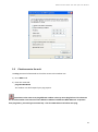
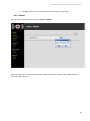
3) The following window shows up
4) Click Internet Protocol (TCP/IP) and then Properties (or double click on Internet Protocol
(TCP/IP))
5) Enter an IP address (ex. 192.168.100.2) under the same subnet as the Default IP Address of
outdoor unit (192.168.100.20)
6) Enter 255.255.255.0 as Subnet Mask
7) Keep the Default Gateway and DNS Server Address as blank
8) Click OK when you finish above settings
14
MIMO 2x2 Wireless Outdoor Access Point System User Manual R2
2.2
Check access to the unit
Use Ping command of DOS mode to check the access to the outdoor unit.
1) Go to DOS mode
2) Enter the command:
ping 192.168.100.20
The outdoor unit shall respond your ping request.
Note that use the same PC to ping different outdoor units may cause ping failure. This is because
the all of the outdoor units share the same default IP address but different MAC addresses. To prevent
from ping failure, you need type command arp –d to clear ARP table on PC before each ping.
15
MIMO 2x2 Wireless Outdoor Access Point System User Manual R2
2.3
Access to web pages
1)
Launch a Web Browser
2)
Enter the default IP address as URL (default IP address: 192.168.100.20) and the initial home
page (login page) will appear
3)
Enter user name (default username: Admin) and password (default password: Wireless)
Note: You need to use the default user name and password when you log in for the first
time.
4)
The System Setting page will come up after you log in successfully
16
MIMO 2x2 Wireless Outdoor Access Point System User Manual R2
2.4
Basic Configuration
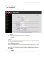
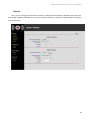
2.4.1 System Setting
This page can be accessed by clicking System > Setting.
1)
Country
You can set the AP to follow different country and region regulation.
2)
IP Address
DHCP Client
Select this if your Internet Service Provider (ISP) uses a DHCP service to assign an IP address to
your router when connecting to the Internet.
Static / Subnet Mask / Gateway
Note that each outdoor unit in the same network must be assigned with an unique IP address.
Therefore, you may need to have a network plan before deployment. Enter the IP address,
Subnet Mask according to the plan. Changes of IP Address / Subnet Mask will be applied after
you click Save.
3)
Password
Change Password by entering a new password twice, click Save and then Reboot. User will be
17
MIMO 2x2 Wireless Outdoor Access Point System User Manual R2
asked to login again with new password after reboot (the password is case sensitive).
4)
SNMP Community
SNMP Community name is a string for administrator to read and write the SNMP MIB from
external SNMP manager. The default SNMP community name is public for read community, and
private for write community. You may change the community name as your plan. Confirm your
setup then clicking Save to perform.
5) System Name & Location
The fields of System Name and System Location is the strings for you to conveniently identify the
different unit. The content of the string is empty by default and can be any ASCII characters
with max. length of 255 characters for both System Name and System Location. Confirm your
setup then clicking “Save” button to perform.
6) ICMP Echo
By default, the value is Enable. Ping is a computer network administration utility used to test the
reach ability of a host on an Internet Protocol (IP) network and to measure the round-trip time
for messages sent from the originating host to a destination computer. The name comes from
active sonar terminology.
Ping operates by sending Internet Control Message Protocol (ICMP) echo request packets to the
target host and waiting for an ICMP response. In the process, it measures the time from
transmission to reception round-trip time and records any packet loss. The results of the test
are printed in the form of a statistical summary of the response packets received, including the
minimum, maximum, and the mean round-trip times, and sometimes the standard deviation of
the mean.
7)
Management VLAN
By default, the values 0 indicates Disable. If you have enabled VLAN tagging on your network,
specify the VLAN tag ID from 2 to 4094. You can assign an SSID to a VLAN. Client devices using
the SSID are grouped in that VLAN
18
MIMO 2x2 Wireless Outdoor Access Point System User Manual R2
8)
NTP
The Network Time Protocol (NTP) is a protocol and software implementation for synchronizing
the clocks of computer systems over packet-switched, variable-latency data networks. The
available NTP server IP & its availability can be found by the following hyperlink
(http://www.pool.ntp.org/en/). Enable this feature and specific the IP address of NTP server IP
to get the system date & time through NTP protocol.
Time zone: specify the time zone that the product located. This setting is based on the GMT
(Greenwich Mean Time).
Daylight Saving Time: Many countries, and sometimes just certain regions of countries, adopt
daylight saving time (DST) during part of the year. It needs to enable or disable based on the
product located countries or area.
Confirm your setup then clicking Save to perform.
9)
Factory Default
Reset All indicates all the settings will return to default value. Reset All, but Keep IP Settings
indicates the IP setting stays and other setting return to default.
Note: Clicking Save will only save your settings on the unit, make sure you click Reboot to
make settings effective.
19
MIMO 2x2 Wireless Outdoor Access Point System User Manual R2
Wireless
Here, you can configure the operation modes for 2.4GHz (AP to be enabled or disabled) and 5GHz to be
AP or Bridge enabled or disabled. Also, you may select the channels, Tx power and WLAN modes according to
your network plan.
20
MIMO 2x2 Wireless Outdoor Access Point System User Manual R2
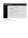
2.4.2 System Information
This page can be accessed by clicking System > Information.
21
MIMO 2x2 Wireless Outdoor Access Point System User Manual R2
This page lists the important system information and software / hardware inventory data.
1)
Uptime
The elapse time since outdoor unit powered up.
2)
IP address / Subnet Mask / Gateway
The IP address / Subnet Mask / Gateway of the wireless unit setting.
3)
Ethernet, 5GHz & 2.4GHz RF MAC
The MAC address of Ethernet and wireless interface.
4)
Firmware Version
The current firmware version running on the outdoor unit.
5)
Traffic Info
The statistic data for the packets transmitted by Ethernet and the wireless interfaces.
22
MIMO 2x2 Wireless Outdoor Access Point System User Manual R2
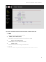
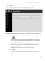
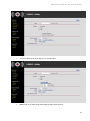
2.4.3 Upgrade
The reboot function can be apply by clicking System -> Upgrade from left side menu
When the new version of firmware has been received, you can upload the file by the web interface for
upgrade the firmware. The page can be access by clicking System -> Upgrade from the left side menu.
Note:
(a). Before upload the new version of firmware, please read the new firmware release
note to confirm the new firmware features, upgrade environment, and procedures can
meet the upgrade requirements.
(b). In case network disruption happens during file uploading, system will still keep on
running with current active firmware. You may perform the file upload again when
network is back to normal.
1) Click Browse and select the firmware files to be uploaded from the PC.
2) Click Upload.
3) When uploading is completed, system will prompt a message asking if you wish to
reboot.
23
MIMO 2x2 Wireless Outdoor Access Point System User Manual R2
4) Click OK to reboot the unit and make the new firmware to take effect.
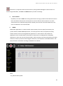
2.4.4 Reboot
You can access reboot function by clicking System > Reboot!.
When starting reboot, system will prompt you a rebooting window. It takes at least 40-60 seconds to
finish the reboot process.
24
MIMO 2x2 Wireless Outdoor Access Point System User Manual R2
3. Configure 2.4GHz AP
3.1 AP Configuration
This page can be accessed by clicking 2.4GHz AP > Setting
1)
SSID
The SSID is the unique name shared among all points in a wireless network. The SSID must be
identical for all points in the wireless network. It is case-sensitive and must not exceed 32
alphanumeric characters, which may be any keyboard character. Make sure this setting is the
same for all points in your wireless network. For added security, you should change the SSID from
the default AP_2G to a unique name. This option can make the SSID invisible from site survey tool.
Enable this function only if you do not want the Access Point to be found by others.
2)
Suppress SSID
When you enable Suppress SSID function, SSID information will be removed from AP broadcast
frame. Thus, only those stations aware of the SSID can associate with AP. The default setting is
disabled.
3)
Security
By default, the security is disabled (No Security). Refer to the next section to configure the
25
MIMO 2x2 Wireless Outdoor Access Point System User Manual R2
security features such as WEP, WPA, WPA-PSK, WPA2 and WPA2-PSK.
•
Select WEP to enable the security mode.
•
Key Entry Method: Hexadecimal: The key must be hexadecimal (0-9, A-F).
•
Key Length: For WEP encryption, the key length can be 10 HEX.
•
Encryption Key: The WEP key can be in one of the following formats: 5 characters, 10 hex
digits, 13 characters, or 26 hex digits.
•
Select WPA to enable the security mode
26
MIMO 2x2 Wireless Outdoor Access Point System User Manual R2
•
Select the WPA mode according to your network plan
•
PSK: he key is an ASCII string with length from 8 to 63 characters
27
MIMO 2x2 Wireless Outdoor Access Point System User Manual R2
•
Enterprise / RADIUS support: enter the IP, port number and other related information to
make the security controlled by your RADIUS server.
28
MIMO 2x2 Wireless Outdoor Access Point System User Manual R2
Note that it is required to have the same security setting between Bridges to communicate. To
make changes take effect, click Save and Reboot when you finish all settings.
4)
RTS Threshold
By default, the value is 2347. This setting determines how large a packet can be before the Access
Point coordinates transmission and reception to ensure efficient communication. This value
should remain at its default setting of 2347. Should you encounter inconsistent data flow, only
minor modifications are recommended.
5)
WMM
Multimedia applications in a WiFi network require Quality of Service (QoS) functionality. The
system default enabled WMM QoS feature, and it will prioritize traffic and optimizes the way
shared network resources among different applications. It works well for data traffic from
applications such as web browser, file transfer, or email, but it is inadequate for multimedia
applications. Voice over Internet Protocol (VoIP), video streaming, and interactive gaming are highly
sensitive to latency increases and throughput reductions, and required to enable QoS feature. The
QoS parameters are default according to IEEE 802.11e as below:
Note:
- AC_BE: Best effort packet
29
MIMO 2x2 Wireless Outdoor Access Point System User Manual R2
- AC_BK: Background packet
- AC_VI: Video packet
- AC_VO: Voice packet
6)
ACL (Access Control)
You may choose to Disable, Allow, or Deny. By selecting Allow, only the address listed in the table
will have access to the network; all other clients will be blocked. On the other hand, select Deny,
means only the listed MAC addresses will be blocked from accessing the network; all other clients
will have access to the network.
MAC Address: Enter the MAC address.
This table lists the blocked or allowed MAC addresses.
30
MIMO 2x2 Wireless Outdoor Access Point System User Manual R2
7)
Max number of STA
You may decide the number of concurrent users that connected the this unit
31
MIMO 2x2 Wireless Outdoor Access Point System User Manual R2
8)
AP User Isolation
By default, it is Disable. You may enable it to prevent any connected users from viewing or
overwriting others contents.
9)
To make changes take effect, click Save and Reboot when you finish all settings.
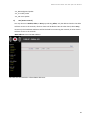
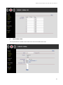
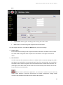
3.2 AP Connection Status
This page can be accessed by clicking 2.4GHz AP > Status
32
MIMO 2x2 Wireless Outdoor Access Point System User Manual R2
This page can help user to identify current devices that already associated to the AP. The MAC addresses
and signal strength for each client will appear.
33
MIMO 2x2 Wireless Outdoor Access Point System User Manual R2
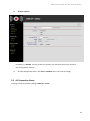
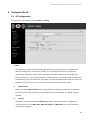
4. Configure 5GHz Bridge
4.1 Bridge Configuration
This page can be accessed by clicking 5GHz Bridge > Setting.
1)
Bridge Mode
By default, it is in Slave. When Master is selected, the remote bridge mode shall set as Slave mode.
One bridge network shall have only one outdoor unit in Master mode, and the others in Slave mode.
2)
Remote Bridge Setup
In order to establish the wireless link between Bridge Radios, the MAC address of remote Bridge(s)
needs to be registered in the address filed. Enter the MAC address with format as xx:xx:xx:xx:xx:xx (x
is the hexadecimal digit). Master Bridge Radio may accommodate up to 8 remote MAC addresses by
the current firmware. In addition, Slave Bridge Radio supports only 1 MAC address which have to be
the Master Bridge
34
MIMO 2x2 Wireless Outdoor Access Point System User Manual R2
3)
Security
Please refer to page 23 for security setting.
WEP:
35
MIMO 2x2 Wireless Outdoor Access Point System User Manual R2
WPA:
•
Cypher Mode: Select Cypher according to the security plan. TKIP or AES.
•
PSK: The key is an ASCII string with length from 8 to 63 characters.
To make changes take effect, click Save and Reboot when you finish all settings
4)
Distance (Km)
Enter the distance according to the longest link between the Master and Slaves in the network.
The value needs to be greater than or equal to the real distance. The range is from 1Km to
35Km.
5)
RTS Threshold
In order to prevent the transmission collision in a hidden nodes environment, Bridge may send a
RTS (Request To Send) before transmitting the data frame from remote Bridge. You may define a
threshold for those frame size greater than the threshold need to activate RTS mechanism. The
valid range is from 256 to 2347. Set low value to this threshold may avoid collision, but the RTS
frame would consume bandwidth.
Note: In Point to Multi-Point application, the transmission collision may be caused by
hidden nodes affection in particular environment or network configuration. Setting smaller
number of RTS threshold could alleviate the hidden nodes problem.
36
MIMO 2x2 Wireless Outdoor Access Point System User Manual R2
6)
Auto Reboot
Default is Disable. When this function is enabled, near-end AP cannot receive alive message
from far-end AP in a certain period. Then this function will perform automatically at near-end AP
without notice. The alive message is communicated between near-end & far-end AP via 5GHz
Bridge links.
7)
To make changes take effect, click Save and Reboot when you finish all settings.
37
MIMO 2x2 Wireless Outdoor Access Point System User Manual R2
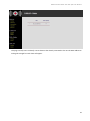
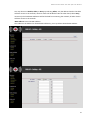
1)
4.2 Bridge Status
This page shows the local and remote Bridges and can be accessed by clicking 5GHz Bridge > Status.
38
MIMO 2x2 Wireless Outdoor Access Point System User Manual R2
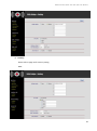
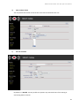
5. Configure 5Hz AP
5.1 AP Configuration
This page can be accessed by clicking 5GHz AP > Setting.
1) SSID
The SSID is the unique name shared among all points in a wireless network. The SSID must be
identical for all points in the wireless network. It is case-sensitive and must not exceed 32
alphanumeric characters, which may be any keyboard character. Make sure this setting is the
same for all points in your wireless network. For added security, you should change the SSID from
the default AP_2G to a unique name. This option can make the SSID invisible from site survey tool.
Enable this function only if you do not want the Access Point to be found by others.
2)
Suppress SSID
When you enable Suppress SSID function, SSID information will be removed from AP broadcast
frame. Thus, only those stations aware of the SSID can associate with AP. The default setting is
disabled.
3)
Security
By default, the security is disabled (No Security). Refer to the next section to configure the
security features such as WEP, WPA, WPA-PSK, WPA2 and WPA2-PSK. For more information,
please refer to page 26.
39
MIMO 2x2 Wireless Outdoor Access Point System User Manual R2
4)
RTS Threshold
By default, the value is 2347. This setting determines how large a packet can be before the Access
Point coordinates transmission and reception to ensure efficient communication. This value
should remain at its default setting of 2347. Should you encounter inconsistent data flow, only
minor modifications are recommended.
5)
WMM
Multimedia applications in a WiFi network require Quality of Service (QoS) functionality. The
system default enabled WMM QoS feature, and it will prioritize traffic and optimizes the way
shared network resources among different applications. It works well for data traffic from
applications such as web browser, file transfer, or email, but it is inadequate for multimedia
applications. Voice over Internet Protocol (VoIP), video streaming, and interactive gaming are
highly sensitive to latency increases and throughput reductions, and required to enable QoS feature.
The QoS parameters is default according to IEEE 802.11e as below.
Note:
- AC_BE: Best effort packet
- AC_BK: Background packet
- AC_VI: Video packet
- AC_VO: Voice packet
6)
ACL (Access Control)
40
MIMO 2x2 Wireless Outdoor Access Point System User Manual R2
You may choose to Disable, Allow, or Deny. By selecting Allow, only the address listed in the table
will have access to the network; all other clients will be blocked. On the other hand, select Deny,
means only the listed MAC addresses will be blocked from accessing the network; all other clients
will have access to the network.
MAC Address: Enter the MAC address.
This table lists the blocked or allowed MAC addresses; you may delete selected MAC address.
41
MIMO 2x2 Wireless Outdoor Access Point System User Manual R2
7)
Max number of STA
You may decide the number of concurrent users that connected the this unit
8)
AP User Isolation
By default, it is Disable. You may enable it to prevent any connected users from viewing or
overwriting others contents.
42
MIMO 2x2 Wireless Outdoor Access Point System User Manual R2
9)
To make changes take effect, click Save and Reboot when you finish all settings.
5.2 5GHz AP Status
This page can be accessed by clicking 5GHz AP > Status.
This page can help user to identify current devices that already associated to the AP. The MAC addresses
and signal strength for each client will appear.
43
MIMO 2x2 Wireless Outdoor Access Point System User Manual R2
6.
Planning Linkage
6.1 Site Survey
You need to consider the following operating and environmental conditions when performing a
site survey:
Data rates – The sensitivity and the radio range are inversely proportional to data rates.
Therefore, the maximum radio range is achieved at the lowest workable data rate, and a
decrease in receiver threshold sensitivity occurs as the radio data rate increases.
Antenna type and placement - Proper antenna configuration is a critical factor in maximizing
radio range. As a general rule, the radio range increases in proportion to antenna gain and
height.
Physical environment - Clear or open areas provide better radio range than closed or filled
areas. Clear line of sight (LOS) is required to establish a good and reliable wireless link.
Obstructions - Metal shelving or a steel pillar can hinder devices. Avoid placing these devices
in locations where those obstructions are between the sending and receiving antennas.
6.2 Planning Radio Path
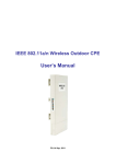
For the wireless communication, the Line-of-Sight (LOS) will be the major issue overbuilding up
the wireless link. This evaluated procedure is to reduce the obstructions and to avoid the
multiple-path signal degrading the communication quality.
The first requirement is the Line-of-Sight (LOS) between the both side Antennas. The radio
line-of-sight concept is the area along the radio linking path through which is the bulk of the radio
signal power travels. The area is known as the first Fresnel Zone of the radio link. For the radio
link, it should avoid to be affected by obstacles in this path, including the ground within 60% of
the first Fresnel Zone.
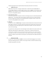
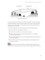
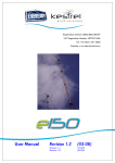
The following figure illustrates the concept of a good radio line-of-sight.
44
MIMO 2x2 Wireless Outdoor Access Point System User Manual R2
Figure 29. Line-of-Sight (LOS)
If there is any obstacle in the radio path, it may still be a radio link but the quality and the signal
strength will be affected. Ensure the maximum clearance from objects on a path is important to
locate the antennas and the height. For the long distance links, the radio signals might be lost
partially due to the non-LOS issue.
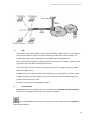
As we setup the radio path for the wireless bridge link, it needs to consider these factors:
Avoid any partial line-of-sight between the antennas.
Be aware of trees that may be near the path or obstruct the path.
Make sure there is enough clearance from buildings and there is no any building or
construction blocking the path.
Check the land topology between the antennas using topographical maps, aerial photos, or
even satellite image data.
Avoid a path that may have the temporary blockage due to the moving objects, such as
cars, trains, or aircrafts.
Note: For the wireless link less than 500m, the IEEE 802.11a radio signal will tolerate
some obstacles in the path and may not even require a visual line of sight between the antennas.
45
MIMO 2x2 Wireless Outdoor Access Point System User Manual R2
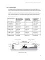
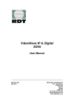
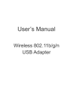
6.2.1 Antenna Height
The reliable wireless link usually depends on the both sides antennas for a clear radio line of
sight. The minimum height is determined by the link distance, obstacles that may be in the path,
topology of the terrain, and the curvature of the earth (for links over 2 miles). For the long
distance links, the mast or the pole may need to be constructed to attain the minimum required
height. The following table is for you to estimate the required minimum clearance above the
ground or path obstruction.
Figure 30. Antenna height
46
MIMO 2x2 Wireless Outdoor Access Point System User Manual R2
For example, the wireless link between the building A and the building B is located three miles
(4.8 km) away. There is a tree-covered hill in middle. From the table above, it can be seen that
for a three-mile link and the object clearance required at the mid-point is 5.4 m (17.6 ft). The
tree-covered hill height is at an elevation of 17 m (56 ft), so the antennas link on both sides
need to be at least 22.4 m (73 ft) high. The building A is six stories high or 20 m (66 ft), so the
mast or pole with 2.4 m (7.9 ft) must be constructed on its roof to meet the required antenna
height. The building B is only three stories high or 9 m (30 ft) but it is located at an elevation
that is 12 m (39 ft) higher than the building A. A mast or pole is required to mount an antenna
at the required height 1.4 m (4.6ft) on the roof of building B.
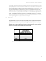
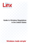
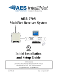
6.3
Data-rate
The following table provides a range and recommended data rate guideline using the build-in
16dBi antenna as examples. User can base on the targeted system performance to select an
appropriate antenna that can support the planned data rate for the application. For example,
the bridge with the build-in 16dBi antenna (when purchased with build-in antenna option) at
both ends could operate well with 6 Mbps data rate up to 25 Km.
Data Rate
Recommended
Maximum Distance
(Build-In 16dBi Antenna)
@5850MHz, 10dB system margin
6 Mbps
25 Km
54 Mbps
2.2 Km
MCS0~3
25 Km
MCS 8~11
12.8 Km
MCS 7
1.4 Km
MCS 15
0.9 Km
Figure 31
Recommended Maximum Distance with 16dBi Built-in Antenna
47