1
AES 7705i
MultiNet Receiver System
Initial Installation
and Setup Guide
AES Corporation
285 Newbury Street. Peabody, Massachusetts 01960-1315 USA
Tel: USA (978) 535-7310.
Fax: USA (978) 535-7313
Copyright 2006/2007, All rights Reserved
40-7705I-IS
Rev 1.1 Sept 25, 2007
AES 7705i MultiNet Receiver
Table of Contents
1.0 Overview ..................................................................................................................... 3
1.1
Product Descriptions: ............................................................................................ 3
2.0 Installation .................................................................................................................. 4
2.1
7170 IP-Link Installation....................................................................................... 4
2.2
MultiNet Receiver Installation .............................................................................. 5
3.0 Software Installation:................................................................................................. 6
4.0 Initial Programming and setup:................................................................................ 6
5.0 Additional Configuration: ......................................................................................... 6
5.1 Operating in Simplest Configuration:...................................................................... 6
5.2 Highlights of Section 6 of the MultiNet User Manual............................................. 7
6.0 Setup 7170 IP-Link Transceivers: ............................................................................ 8
7.0 Test your Network Settings:...................................................................................... 9
8.0 Test Communication from Subscribers: ................................................................ 10
9.0 Initial Installation Complete: .................................................................................. 10
10.0
Contact information:......................................................................................... 10
This product shall be installed in accordance with NFPA 72,
NEC, UL 827 and all applicable local codes
40-7705I-IS
Page 2
Rev 1.1 Sept 25, 2007
1.0 Overview
This document discusses the initial installation, setup and configuration of the
AES MultiNet Receivers and its 1st 7170 IP-Link Transceivers. This document is
to be used in conjunction with other provided documentation. It is intended to
provide an organized process while focusing on sections of other documents that
are needed for this initial installation process.
In many cases this document will direct you to a section in another document.
Although not a requirement, it is generally a good idea to set up your MultiNet
System and become familiar with its operation before it is put into an active
operational mode. This could be accomplished by a temporary simple setup
followed by the relocation or connection in the intended central station network or
could be the final installation but not put into active use until ready.
1.1 Product Descriptions:
General descriptions of the equipment used in the MultiNet system can be found
in section 1 of the “AES 7705i MultiNet Receiver System – User Manual”. Refer
to that section to get familiar with the components and general makeup of this
system.
40-7705I-IS
Page 3
Rev 1.1 Sept 25, 2007
2.0 Installation
The installation process outlined in this document suggests that you first install
the 7170 IP-Link transceiver to the point where power is to be applied. Then
continue by installing, powering and configuring the 7705i MultiNet receiver
followed by the powering and configuration on the 7170 installed previously.
This is by no means a requirement but a suggestion and geared for those who are
installing equipment prior to the visit of an authorized factory technician.
2.1
7170 IP-Link Installation
The first two 7170’s are typically installed at the same physical location as the
MultiNet receiver. They should be positioned as close to the location of the RF
antenna as possible. The location should be selected to produce the shortest and
straightest run of coax to the antenna through the bandpass cavity and surge
protector. 200 foot separation of the antennas, IP-Link and associated equipment
must be maintained to have proper system supervision.
The IP-Link Transceiver and bandpass cavity should be located inside away from
the elements. Refer to the provided “AES 7170 IP-Link Transceiver Installation
and Operation Manual” for installation details.
The antenna and any surge devices should be bonded to a good earth ground in
accordance with the National Electric Code and any applicable Local Codes.
The 7170 IP-Link transceivers should be installed and preparations made to
connect to power, phone and network. Follow the installation instruction in the
“AES 7170 IP-Link Transceiver Installation and Operation Manual”
provided with the units and stop at the point where you are instructed to connect
or initiate power. An outline of the process is below.
•
IP-Link Transceiver installation steps:
1.
2.
3.
4.
5.
6.
40-7705I-IS
Mount the transceiver in your selected location.
Install the bandpass cavity, surge protector, antenna and coax.
Prepare phone connection.
Prepare network connection.
Prepare but do not connect the AC power connections.
Continue with MultiNet receiver installation prior to initial power up.
Page 4
Rev 1.1 Sept 25, 2007
2.2
MultiNet Receiver Installation
Refer to section 4 of the “AES 7705i MultiNet Receiver System – User Manual”
and the following additional information on the Installation and Setup
•
Directly connected keyboard, video monitor and mouse are required for initial
setup.
•
The 7705i, monitor and any network related equipment must be connected to
a suitable UL Listed, 864 UPS to maintain power during power outages.
•
Each MultiNet receiver /7170 IP-Link Transceiver pair is shipped with
identical configurations. At least one pair’s TCP/IP configuration must be
changed before connecting the two into the same network together.
•
Refer to Figures 4-1, 4-1, and 4-3 in the “AES 7705i MultiNet Receiver
System – User Manual” for system illustrations.
•
MultiNet receiver installation steps:
1. Mount or locate the 19” rack mountable MultiNet receiver in your selected
location. A UL Listed (UL864) 19” rack is required.
2. Install and connect the monitor, keyboard and mouse to the proper
connections on the rear panel of the Receiver. Keyboard and mouse
connect using the provided Y cable. This is for initial setup only.
3. No Ethernet port should be connected to an existing live network until the
settings have been confirmed and or modified. Leave the Ethernet cables
disconnected for 1st time power up, if connecting to a live network with
other active or in use devices.
a. Because the MultiNet Receiver is preconfigured to operate as
shown in Figure 4-1 of the MultiNet Receiver System User
Manual, it is OK to connect a 7170 IP-Link Transceiver to Port 1
of the MultiNet Receiver using an Ethernet Crossover cable which
you should be able to purchase from a computer supply store.
b. Once TCP/IP is configured you can connect the Ethernet port(s) to
appropriate connections of your network to enable communication
to the IP-Link Transceiver(s) and secondary MultiNet Receiver(s).
c. You may connect a single 7705i and a 7170 to a private network
such as to a dedicated router. Whereas there are no other network
devices other than the router itself, there should be no conflicts.
Before connecting the second system the first should be changed or
disconnected until changes are made to the second. Once both
pairs have unique settings, they can both be connected to the same
router/private network.
4. Connect printer. Attach only a printer Listed by UL for “Signaling use”
such as an AES 75-0101.
5. Plug MultiNet receiver, monitor and printer power cords into appropriate
power sources. A UL Listed UPS (UL864) or UL1481 power supply is
required.
40-7705I-IS
Page 5
Rev 1.1 Sept 25, 2007
3.0 Software Installation:
All necessary software is pre-installed on your 7705i
If your system has a catastrophic failure it may require the reinstallation of the
Linux operating system and the specialized IP-Link software programs. BIOS
settings should also be checked to confirm that the unit would initialize and
operate properly.
Contact AES technical Support for software assistance.
4.0 Initial Programming and setup:
Section 5 “System Startup and Access” of the “MultiNet Receiver System User
Manual,” should now be followed to power up, login and perform the steps
needed to configure your MultiNet Receiver for operation in your local area
network (LAN).
Keep in mind that the simplest configuration may be to connect your 7170 IPLink Transceiver’s Ethernet Port directly to Ethernet Port 1 on the MultiNet
receiver and operate without a network using a CAT5 Crossover Cable (available
separately from a computer supply store). This configuration is useful for quick
setup to become familiar with the system before its final deployment in your
target network. This is illustrated in Figure 1 of the manual.
5.0 Additional Configuration:
Section 6 “Admin GUI for Configuration and Administration” of the “MultiNet
Receiver System User Manual,” is the next section to follow. Instructions in that
section assume you are now connected to a network that has a workstation with a
Web browser.
5.1 Operating in Simplest Configuration:
If you are operating in the temporary simplest configuration as shown in Figure 4
in the User Manual, you may not have access to a remote workstation. Follow
these steps to start a Web Browser using the directly connected Keyboard, mouse
and monitor to be able to proceed with section 6.
1. Login as root
2. Enter the following to start the GUI. startx<Enter>
3. Start a new terminal. Right click and select New terminal
4. At the command prompt in the terminal type the following command:
konqueror<Enter>
5. This will start the Konqueror Web Browser. It may take a minute to start.
6. Enter the following URL in the location box: http://localhost/Admin/
7. You may now continue with section 6 to login to the Admin GUI.
8. Be advised: there is no shortcut provided to exit the Admin GUI initiated
in step 2 above. After closing or exiting the programs you initiated after
starting the GUI, either select Reboot Server or press <Ctrl> + <Alt> +
<Backspace> to force the system to “kill” the x-server GUI.
40-7705I-IS
Page 6
Rev 1.1 Sept 25, 2007
5.2 Highlights of Section 6 of the MultiNet User Manual
Once you have logged in to the Admin GUI As instructed in Section 6 of the User
Manual, you can select links to perform a number of configuration functions.
Listed below are some areas to pay attention to assuming this is your first time
using the Admin GUI.
•
Server Configuration where you will set some important server parameters
•
Define your first Business Unit.
o No user Business Unit, exits from the factory default
configuration. You need at least one.
o If you cannot select a name at this time “use a name like
“PrimaryBusinessUnit” or the name of an organization or a word
related to the purpose of this Business Unit. You could later delete
it and create one once you become familiar with its purpose.
o Select Data Type: “Security”, but for now do not select “Alarm
Automation System? ”.
o Select “Universal ID”. You need to know the ID of the IP-Link(s).
Factory default for the IP-Link is ID 1111
•
If you did not select Universal ID then add Subscriber ID’s to the Business
Unit. By selecting Universal ID on the first page of creating the Business
Unit, all messages from the IP-Links listed will automatically be
associated with this Business Unit. If you do not select Universal ID then
every Subscriber ID must be entered into each Business Unit’s database
manually. Any messages from an ID not in a database will be sent to the
Business Unit named orphan. The orphan Business Unit is discussed in
Section 6.2 of the 40-7705i MultiNet Receiver System – User Manual.
After successfully completing the tasks outlined in Sections 1 through 6 of the
“MultiNet Receiver System – User Manual”, you should be ready to power up,
configure as shown in figure 4-2 or figure 4-3 of 40-7705I-UM and bring your
7170 IP-Link transceiver(s) online.
•
If you are finished using the Admin GUI Web pages then you should
close your Web Browser to avoid unauthorized access to system sensitive
configurations.
•
If you are directly logged into the MultiNet receiver then you should
Logout the user.
•
If you were running the x-server GUI from the directly attached keyboard
monitor and mouse started by entering the startx command, then it would
be advisable to select “Reboot Server!” from the right click menu thus
beginning from a clean start of the system.
40-7705I-IS
Page 7
Rev 1.1 Sept 25, 2007
6.0 Setup 7170 IP-Link Transceivers:
The 7170 IP-Link Transceiver wants to connect to its assigned MultiNet Receiver when it
starts. For that reason, you will want to have configured and started the 7705i as outlined
in the manual up to this point.
Refer to Section 8 “Programming and Setup in the “7170 IP-Link Transceiver –
Installation and Operation Manual” for specific details and instruction for the installation.
Prerequisites:
•
The AES 7705i MultiNet Receiver(s) must be on and connected to the network or
ready for direct connection to the IP-Link Ethernet Port.
•
The MultiNet receivers should have their AES Programs running.
•
If using static IP then you need to know the IP address, Netmask and Gateway for
each 7170 being configured. Even if using DHCP you need to have the static IP
address of the Gateway.
•
You need to know the phone number(s) to the MultiNet receiver(s). If you are not
ready with these you can still continue but will receive messages when
communication attempts fail.
•
You will need a serial terminal to attach to the serial port of the 7170 to access the
built-in programming functions. Microsoft HyperTerminal or similar program on
a Windows PC will work well for this purpose.
•
Make sure that the antenna or a proper load is attached to the antenna connection
of the IP-Link Transceiver.
Continue with 7170 IP-Link Installation and Operation Manual:
It is now time to return to where you left off in the AES 7170 IP-Link Transceiver –
Installation and Operation Manual on page 14.
40-7705I-IS
Page 8
Rev 1.1 Sept 25, 2007
7.0 Test your Network Settings:
Assuming you completed all the tasks in the 7170 IP-Link Installation and Operation
manual you have already performed testing from the IP-Link. It is now time to return to
the MultiNet Receiver and perform some additional testing.
Listed Sections refer to the AES MultiNet Receiver System - User Manual
•
Log in to the MultiNet Receiver as user root. (Refer to Section 5.4).
Or if you have established remote VNC access then select “New Terminal” form
the AES Menu on the desktop.
•
Ping another device on the network.
Ping another known computer or device that is on your network to determine if
the configuration is working properly. At the command prompt in the terminal,
issue the following command replacing {network ID of another computer} with
the IP address of the gateway, or other known PC on the network.
ping –c4{network ID of another computer}<Enter>
Example:
ping –c4 192.168.0.1<Enter> (Default Gateway PC)
or
ping –c4 192.168.0.11<Enter> (Default System 1 7170 setting)
The above listed ping commands will ping 4 times (-c4), either the default
Gateway, assuming it is 192.168.0.1 or the 1st 7170 assuming it is set to
192.168.0.11.
You can ping the address of the receiver itself to see how the ping program works.
Example: Ping –c4 192.168.0.101<Enter> (Default Receiver setting)
If necessary press <Ctrl> + C to stop pinging attempts or get a command prompt.
Received responses indicate how long the response took, if it failed or timed out.
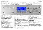
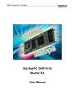
Example below shows the “ping –help” response, a successful and a failed ping.
Figure H - Example of a ping to a gateway PC.
40-7705I-IS
Page 9
Rev 1.1 Sept 25, 2007
8.0 Test Communication from Subscribers:
•
Power up and program a Subscriber
•
Program it with a unique ID and the same Cypher Code programmed into the
7170 IP-Link Transceiver.
•
Generate some signals and confirm reception of expected messages using one or
more of the following methods:
o If available, using the IPCtrl program.
o If connected and functional, using the attached Event Printer.
o If connected and configured using the Alarm Monitoring System.
o Using subscriber database section of the Admin GUI
(Subscribers / View).
9.0 Initial Installation Complete:
You have completed your initial installation if your testing was successful.
You should now be ready to familiarize yourself with the MultiNet System
operation and use. Then, once you have become familiar with the system
you should be confident with introducing it into your existing or new central
station network and environment. You will then be ready to begin using
your MultiNet system to provide your customer base with the reliable data
communication capability they expect and deserve.
10.0 Contact information:
Below is the contact information for AES, if you need assistance with the installation or
operation of your MultiNet Receiver System,
AES corporate Phone:
(800) 237-6387 (800) AES-NETS
USA (978) 535-7310
Fax:
USA (978) 535-7313
Website:
http://www.aes-intellinet.com
Email:
[email protected]
40-7705I-IS
Page 10
Rev 1.1 Sept 25, 2007