1
D NA EC
CORPORATION
Dynalec Integrated Announcing System
User’s Manual
Dynalec Corporation
87 West Main Street
Sodus, NY 14551
(315) 483-6923
http://www.dynalec.com/
Rev 07NOV01
Table of Contents
Safety Precautions and General Information ...................................................................................5
System Description ..........................................................................................................................6
Salient Characteristics..........................................................................................................6
System Components.............................................................................................................7
Main/Amplifier Interface Module............................................................................8
Auxiliary Amplifier Interface Module.....................................................................8
Legacy Mic Interface Module..................................................................................9
PBX/IVCS Modem Interface Module .....................................................................9
Amplifier Chassis.....................................................................................................9
Ship’s Wiring Tray ................................................................................................10
Operation........................................................................................................................................11
Using the User Interface ....................................................................................................11
Display & Display Adjustments ............................................................................11
“Softkey” Push-button Switches............................................................................12
Scroll Knob ............................................................................................................12
Loudspeaker, Bargraph, and Volume Control .......................................................12
Configuring the System .....................................................................................................13
Voice Channels ......................................................................................................14
Alarm Channels .....................................................................................................15
Voice Channel “Blocks” ........................................................................................15
Amplifier Configuration ........................................................................................16
Amplifier Sparing (Amplifiers 6 & 12) .................................................................16
Configuring the Amplifiers via the User Interface ................................................17
Configuring the Mic Station Priority via the User Interface..................................18
Configuring the Alarm Generator via the User Interface ......................................18
Changing the PIN Number via the User Interface .................................................19
Reviewing the System Configuration ................................................................................20
Testing the System.............................................................................................................21
Testing the Alarm Generators................................................................................21
Testing the Amplifier Modules..............................................................................22
1
Auxiliary System Outputs..................................................................................................23
Visual Indicator Output..........................................................................................23
Entertainment System Attenuate............................................................................23
Entertainment System Mute...................................................................................23
Alarm Active..........................................................................................................23
Alarm Operation ................................................................................................................24
PBX Interface Operation....................................................................................................24
IVCS Modem Interface Operation.....................................................................................25
Suggested Configurations for Legacy-type Applications ..................................................26
Suggested Configuration for an AN/SIA-114B Application .................................26
Suggested Configuration for an AN/SIA-117B Application .................................28
Suggested Configuration for an AN/SIA-118A Application.................................31
Parts Lists.......................................................................................................................................33
Top Level System Parts List ..............................................................................................33
Ship’s Wiring Tray Assembly Parts List ...........................................................................41
Ship’s Wiring Tray PCB Assembly..................................................................................44
Main/Amp Interface Module Parts List .............................................................................48
Auxiliary Amp. Interface Module Parts List .....................................................................52
Legacy Mic Interface Module Parts List ...........................................................................55
PBX/IVCS Modem Interface Module ...............................................................................58
Amplifier Chassis Assembly..............................................................................................61
250W Amplifier Module....................................................................................................64
Fan Tray Assembly............................................................................................................67
Installation......................................................................................................................................71
Mounting and Outline Drawing .........................................................................................71
System Input Power ...........................................................................................................71
Ship’s Wiring .....................................................................................................................73
Mic Station Connections........................................................................................73
Alarm Contactor Connections................................................................................75
PBX Interface Connections....................................................................................76
Amplifier Output Interface Connections ...............................................................77
Local Loudspeaker Cutout Connections................................................................77
2
Mic Interface DIP-switch Adjustment ...............................................................................78
Amplifier Sparing Configuration.......................................................................................81
Interconnect Diagram.........................................................................................................82
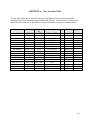
Appendix A – Fuse Location Table ...............................................................................................86
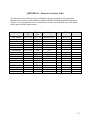
Appendix B – Firmware Location Table .......................................................................................87
3
List Of Figures
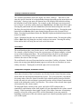
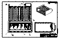
Figure 1 – System Components .......................................................................................................7
Figure 2 – User Interface ...............................................................................................................11
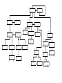
Figure 3 – User Interface Menu Tree.............................................................................................13
Figure 4 – Amplifier Module Front Panel .....................................................................................22
Figure 5 – PBX/IVCS Modem PCB DIP-Switch ..........................................................................25
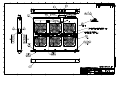
Figure 6 – Assembly, Digital Integrated Announcing System – Sheet 1 ......................................38
Figure 7 – Assembly, Digital Integrated Announcing System – Sheet 1 ......................................39
Figure 8 – Assembly, Digital Integrated Announcing System – Sheet 1 ......................................40
Figure 9 – Assembly, Ship’s Wiring Tray Module........................................................................43
Figure 10 – Assembly, Ship’s Wiring Tray PCB ..........................................................................47
Figure 11 - Assembly, Main/Amp Interface Module....................................................................51
Figure 12 – Assembly, Auxiliary Amp Interface Module .............................................................54
Figure 13 – Assembly, Legacy Mic Interface Module ..................................................................57
Figure 14 – Assembly, PBX/IVCS Modem Interface Module ......................................................60
Figure 15- Assembly, Amp. Chassis .............................................................................................63
Figure 16 – Assembly, 250W Amplifier Module ..........................................................................66
Figure 17 – Assembly, Fan Tray....................................................................................................70
Figure 18 – Input Power Connections ...........................................................................................71
Figure 19 – Mounting and Outline Drawing..................................................................................72
Figure 20 – Ship’s Wiring Board Layout ......................................................................................78
Figure 21 – Legacy Mic Interface Module Assignment Dip-switch .............................................79
Figure 22 – Legacy Mic Interface Input Level Control DIP-switch..............................................80
Figure 23 – Amplifier Chassis Spare Configuration DIP-switch ..................................................81
Figure 24 – System Interconnect Diagram ....................................................................................82
4
Safety Precautions
and General Information
Safety Precautions
The following paragraphs contain general safety precautions that are not related to any specific
procedures and therefore do not appear anywhere else in the publication. These are precautions
that must be observed during the performance of any operation or maintenance task.
Live Circuits
Operation of this equipment requires the use of high voltages which may be dangerous to
life. Operation and maintenance personnel must perform the following prior to working
on equipment:
1. De-energize power circuit to unit prior to working on any part of the unit.
2. Tag circuit where it is de-energized to warn other personnel so they do not
energize the circuit.
3. Discharge and ground circuits to assure they are de-energized prior to touching
them.
Service Restrictions
DO NOT service or adjust equipment alone. Under NO circumstances should any
personnel reach within an enclosure for any purpose without the presence or assistance of
another person capable of rendering aid.
5
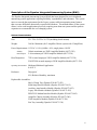
Description of the Dynalec Integrated Announcing System (DIAS)
The Dynalec Integrated Announcing System (DIAS) has been designed for use in shipboard
announcing system applications requiring flexibility, expandability, and robustness. The system
meets or exceeds the requirements for the Legacy systems while incorporating many features
that overcome difficulties historically experienced with them. The modular nature of the system
allows it to be used in applications previously requiring more than one system and also permits
expansion to accommodate the ever-changing system.
Salient Characteristics
Size:
22.1”W x 63.8”H x 26.3”D (including shock mounts)
Weight:
360 lbs. Maximum (for 2-Amplifier Chassis system with 12 amplifiers)
Power Requirements: 115VAC ± 10% @ 60Hz ± 10%, single phase, 0.98 PF
Standby:
300mA maximum per 250W Amplifier Module (60173-350)
Rated Output:
2.8A maximum per 250W Amplifier Module (60173-350)
Heat Dissipation:
72W at rated output per 250W Amplifier Module (60173-350)
250 BTU/Hr at rated output per 250W Amplifier Module (60173-350)
Operating Environment:
Shipboard Sheltered Application
0 to 65°C
Enclosure:
Drip-proof
95% Relative Humidity, maximum
Replaceable Assemblies:
Ship’s Wiring Tray (Dynalec P/N 60173-435)
Main/Amp Interface Module (Dynalec P/N 60173-415)
Auxiliary Amp Interface Module (Dynalec P/N 60173-455)
Legacy Mic Interface Module (Dynalec P/N 60173-425)
PBX/IVCS Modem Interface Module (Dynalec P/N 60173-445)
Amplifier Chassis Assembly (Dynalec P/N 60173-300)
250W Amplifier Module (Dynalec P/N 60173-350)
Fan Tray Assembly (Dynalec P/N 60173-236)
6
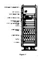
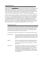
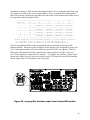
Figure 1
7
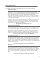
Integrated Announcing System Components
Refer to Figure 1 on page 7 for locations of the various system components in the DIAS rack.
Main/Amplifier Interface Module
The Main/Amplifier Interface Module (Dynalec P/N 60173-415) is responsible for the
following system functions:
•
Controlling the User Interface (see Using the User Interface section of the
Operation chapter on page 11)
•
Routing audio from mic stations (or other sources) to amplifier modules in
Amplifier Chassis #1 as dictated by the system configuration
•
Generating alarm signals from one of two redundant Alarm Generators as
dictated by the system configuration
•
Maintaining periodic communication with the Amplifier Chassis to report
faults in any of the system amplifier modules
•
Generating auxiliary signals (entertainment system attenuate/mute, visual
alarm indicator, alarm active contact closure) as necessary
•
Converting 115VAC input power to the DC power required for all other
modules
•
Test amplifier modules and Alarm Generators as requested by the user via
the User Interface
•
Report test results to user via the User Interface
The Main/Amplifier Interface module is required for all systems, regardless of
configuration.
Auxiliary Amplifier Interface Module (optional)
The Auxiliary Amplifier Interface Module (Dynalec P/N 60173-455) is required only in
systems that use a second Amplifier Chassis (since the Main/Amplifier Interface Module
[see above] can only handle routing to 6 amplifiers). This module handles only the
routing function described above and it is powered by the DC power generated in the
Main/Amplifier Interface Module.
8
Legacy Mic Interface Module
The Legacy Mic Interface Module (Dynalec P/N 60173-425) contains the interface
circuitry to interface with any combination of four Legacy Mic Control Stations
(IC/MSB-2), Mic Jack Boxes (IC/MJB-2), or M-136A/SIC Microphones.
Each interface consists of a transformer-coupled input audio pair, which can
accommodate standard mic level (-50dBm) or can be switched via an internal DIP-switch
(see the Mic Interface DIP-switch Adjustment section on page 77) to accommodate
standard line level (0dBm) (see PBX/IVCS Modem Interface below). In addition, each
interface accepts group select signals for up to 10 announcing system groups and a PTT
signal. Each interface provides a busy signal for each group “block” (see the Configuring
the System section of the Operation chapter on page 13 for definition of a group “block”),
an audio output derived from the actual amplifier output(s) for driving the visual
indicator on an IC/MSB-2, and a cutout signal for local loudspeaker cutout (see the Local
Loudspeaker Cutout Connection section on page 76).
Connectivity to the Legacy Mic Interface Module is accomplished through the Ship’s
Wiring Board (see page 10). Each mic interface has its own connectors and the signals
are labeled on both the board silkscreen and on the C-size print included in the pocket
provided inside the door of the system.
PBX/IVCS Modem Interface Module
The PBX/IVCS Modem Interface Module (Dynalec P/N 60173-445) also contains four
interfaces to the announcing system. However, this module is more specialized in that
one of the four interfaces is dedicated to connecting to a Modified IVCS Modem
(Dynalec P/N 62300-127-1) to allow announcements through a STC-II telephone system
(see the Installation section for connectivity).
In addition, one of the four interfaces is dedicated to connecting to up to six standard
analog line interfaces (POTS interfaces). In this manner, the functionality of the IVCS
Modem is duplicated without an extra piece of hardware and is accomplished using
industry standard analog line interfaces.
The remaining two of the four interfaces are identical to the Legacy Mic Station
interfaces on the Legacy Mic Interface Module (see description above).
Amplifier Chassis
The Integrated Announcing System can accommodate up to 2 Amplifier Chassis
(Dynalec P/N 60173-300). Each chassis can hold up to six 250W Amplifier Modules
(Dynalec P/N 60173-350) and can be configured so that one of the six is a spare module
which is automatically switched in upon detection of a fault in one of the other five.
9
Each amplifier module incorporates its own independent circuitry and is separately fused
so that any faults that may occur are isolated from the other modules. Each module also
has its own power switch so that amplifiers may be swapped without affecting the
operation of the other modules.
Each Amplifier Chassis connects to the Main/Amplifier Interface Module through
internal rack wiring and input audio is routed from the various input interface modules
(Mic Interface Module or PBX/IVCS Modem Interface Module) to each amplifier
module based on the system configuration. Each amplifier output is directed to the
Ship’s Wiring Tray (see below) and is also connected to the Main/Amplifier Interface
Module for routing back to Mic Control Stations for VU meter indications.
The Main/Amplifier Interface Module also periodically obtains diagnostic information
from each Amplifier Chassis and reports any faults to the User Interface.
At least one Amplifier Chassis is required for all systems.
Ship’s Wiring Tray
All connections between the ship’s wiring and the Integrated Announcing System are
made at the Ship’s Wiring Tray (Dynalec P/N 60173-435). The Ship’s Wiring Board
(mounted in the tray – Dynalec P/N 60173-430) has connectors for 16 Mic Station
Interfaces, Alarm Contactor Inputs for the 5 alarm signals, IVCS Modem Interface,
Analog Line Interfaces (6 lines), and Loudspeaker Interfaces (including Local
Loudspeaker Disconnect connections). All connectors are Euroblock-type connectors to
facilitate simple wiring of the system.
10
Operation
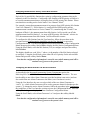
Using the User Interface
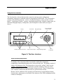
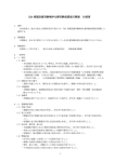
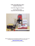
The User Interface is the mechanism in the system for entering system configuration
information, entering test commands, and receiving diagnostic information. The User Interface
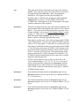
consists of the following elements: a 4-line x 20-character display, a rotary encoder (“Scroll
Knob”), 3 push-button “softkey” switches, a backlight intensity knob, a display contrast knob, an
LED-based bargraph display, a loudspeaker, and a loudspeaker volume knob (see Figure 2
below).
Display
"Softkey" Push-button Switches
Scroll Knob
Bargraph Display
Display Contrast Adjust
Local Loudspeaker
Volume Control
Display Backlight Adjust
Local
Loudspeaker
Figure 2 : The User Interface
Display & Display Adjustments
The display is the component of the User Interface which allows diagnostic,
configuration, and testing information to be conveyed to the user. The display consists of
4 lines of 20 characters each. The bottom line is reserved for “softkey” labels (see the
“Softkey” Push-button Switches section below) and the remaining 3 lines are used to
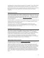
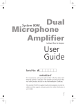
display information specific to the menu that is being accessed. Figure 3 illustrates the
“tree” structure of the menus and shows how to get from menu to menu.
Because various conditions of the operating environment may require different display
characteristics, adjustments are included for the intensity of the LED backlighting and the
contrast of the display.
11
“Softkey” Push-button Switches
The 3 buttons immediately below the display are called “softkeys”. This term is used
since the specific function of each push-button changes depending on the menu shown on
the display. On any given menu, the bottom line of the display holds labels describing
the functions of each of the buttons. For example, on the main menu screen (top-most
box on Figure 3), the three softkey labels are Conf, Review, and Test (from left to right).
Pressing the push-button below the Conf label (left-most button) brings the user to the
Pin-Entry Screen which will take the user to the Configuration Menu. Pressing the pushbutton below the Review label (center button) brings the user to the System Review
Menu. Pressing the push-button below the Test label (right-most button) brings the user
to the Test Menu.
Figure 3 illustrates how the user can maneuver from menu to menu. Pressing the softkey
below a Back label will bring the user back to the previous menu. Pressing the softkey
below an Esc label will bring the user back to the main menu.
Scroll Knob
The scroll knob provides a way for the user to “scroll” through several input selections.
For example, on the Pin-Entry Screen, the user must enter a 4-digit pin number to obtain
access to the Configuration Menu. The scroll knob allows the user to scroll through
numbers 0-9 for the digit with the cursor beneath it and the softkey with the label >
advances the cursor to the next digit.
The scroll knob is also used for menus that have more than 3 softkey selections. On these
menus, the message {use knob for more} appears to inform the user that there are more
softkey selections. Turning the scroll knob right or left accesses them.
Loudspeaker, Bargraph, and Volume Control
These three elements of the User Interface are all related to the Alarm Generator testing
feature built into the Integrated Announcing System. The system includes a mechanism
for testing either of the two Alarm Generators in the Main/Amplifier Interface Module.
In this test mode, the selected alarm is generated from the selected Alarm Generator and
routed to the loudspeaker on the User Interface. The volume of the selected alarm signal
is determined by the volume control.
The bargraph display consists of red, green, and yellow LED’s and provides a
quantitative representation of the alarm signal level (not dependent on the volume control
setting). When a particular alarm signal is tested, if the Alarm Generator is functioning
properly, at least one of the green LED’s will be illuminated (it may not remain lit,
depending on the nature of the select alarm signal, but it should repeatedly light for each
cycle of the signal).
12
Main Menu #1
0
0 Fault(s) Present
Config Review
2
ESC
Enter
12
Please Enter Pin
XXX
Invalid Pin
Back
>
To Main Menu
#0
System Review Menu
Please Select Option
More options Avail.>
ESC
Agen
Amp
To Main Menu
#0
Roll Selection
System Review
Please Select
<More options
ESC
Mic
4
Configuration Menu
Please Select Option
More options Avail.>
ESC
Agen
Amp
Configuration Menu
Please Select Option
<More options Avail.
ESC
Mic
Pin
To Main Menu
#0
15
Current Alarm
Generator 1
5
ESC
To Review
Menu #12
To Main Menu
#0
ESC
Select
Back
To config
Menu #4
To config
Menu #4
ESC
Select
To Main Menu
#0
Select Mic 1
Priority Level: 1
Back
To config
Menu #4
8
Amp 1
A4 A5
V5 V6
Enter
To config
Menu #4
11
9
1
Select
ESC
Select
To Main Menu
#0
To Main Menu
#0
A3
V4
V10
Back
To amp
Selection
Menu #7
ESC
Back
Test Menu
Please select option
To Main Menu
#0
To Review
Menu #13
ESC
A1 A1 A2
V1 V2 V3
V7 V8 V9
toggle
Back
Back
To config
Menu #5
Please Select Alarm
Generator 1
To Amp
Selection
Menu #15
To Amp
Selection
Enter
To config
Menu #5
ESC
ESC
Set
Back
To Mic
Selection
Menu #9
To Test
Menu #21
23
Generator 1
Select Alarm Signal
Alarm # 1
ESC
Select Back
To Main Menu
#0
Mic 1 Monitor
PTT VVVVVVVVVV
1234567890
ESC
To Main Menu
#0
20
To Gen
Selection
Menu #22
26
Amp XX Monitor
Back
To Sysmon
Menu #18
Select Amp
1
ESC
Select
To Main Menu
#0
Back
To Test
Menu #21
25
System Activity
Mic 1234567890123456
Amp 123456789012
ESC
Mic
Amp
19
24
Back
18
>
Roll
Selection
To Main Menu
#0
To Mic
Selection
Menu #9
Select
To Main Menu
#0
Mic 1
Select Priority 1
To Main
Menu #0
Amp
22
A3
V4
V10
Back
Enter New Pin
1234
To config
Menu #5
Agen
To Main Menu
#0
10
A1 A1 A2
V1 V2 V3
V7 V8 V9
toggle
21
Back
To Review
Menu #12
16
7
Select Amp
1
Mic 1
Priority Level: 1
Amp 1
A4 A5
V5 V6
Enter
6
17
Select Amp
Back
To Main Menu
#0
Menu
Option
Avail.
SysMon
To Main Menu
#0
14
ESC
Main Menu
13
To Main Menu
#0
To Main Menu
#0
On Activation
of Alarm
Test
1
3
Please Enter Pin
0
Please Select Alarm
Generator 1
0 Fault(s) Present
Alarm 1 Active
Level ....!......
ESC
Back
To Main Menu
#0
To Sysmon
Menu #18
Generator 1
Verify Alarm Level
Alarm # 1
ESC
Back
To Main Menu
#0
To alarm
Selection
Menu #23
Amp 1
Faults and Info
ESC
To Main Menu
#0
Back
To Amp
Selection
Menu #24
Configuring the System
The Integrated Announcing System is designed to be a flexible system that can be configured to
handle a wide variety of requirements. In an attempt to keep the system as flexible as possible,
the definitions of the announcing groups had to kept general enough so as to not limit potential
applications.
Voice Channels
The system consists of 10 Voice Channels. They are referenced in the system
configuration as V1 through V10. Each one of these Voice Channels can be assigned to a
specific announcing system group. Examples of the announcing system groups are
Officers (1MC1), Topside (1MC2), Crew (1MC3), Flight Deck (5MC), and Bullhorn
(6MC).
Each of these 10 Voice Channels corresponds to a group select line on each of the Mic
Station Interfaces (labeled V1-V10 on the Ship’s Wiring Board). When an
announcement is made via one of the 16 Mic Station Interfaces, the Voice Channels
associated with that announcement depend on the group select lines (V1-V10) which are
activated by the Mic Station when the PTT line is activated.
Each amplifier in the system is configured to broadcast any of the Voice Channels.
Amplifiers can also be configured to broadcast more than Voice Channel. In the system,
there is a built-in priority with Voice Channel 1 (V1) being the highest priority and Voice
Channel 10 (V10) being the lowest priority. If an amplifier is configured to broadcast
announcements from more than one Voice Channel and the announcements occur
simultaneously, only the announcement on the highest priority voice channel (the Voice
Channel closest to V1) is broadcast.
An example of the multiple-Voice Channel configuration for an amplifier is the
1MC/3MC configuration typically handled by an AN/SIA-117. Consider the following
configuration: the Officers announcing group is assigned to V1 and the Flight Deck
Walkways group (3MC1) is assigned to V6. If an amplifier was configured for both V1
and V6, then the Flight Deck Walkways announcements would be broadcast to the
loudspeakers connected to the amplifier unless an Officers announcement was initiated.
In that configuration, the Officers announcement would override the Flight Deck
Walkways announcement.
Note that the system is not aware of what Voice Channels are assigned to which
announcing groups. The correlation between Voice Channels and announcing groups is
made through the Mic Control Station connections (i.e. the group select switch labeled
Officers is connected to the V1 terminal on the Euroblock connector for that Mic Station
in the above example) and through the amplifier configurations (i.e. the amplifier
configured to broadcast from the V1 Voice Channel is connected to loudspeakers
intended to take Officers group announcements).
14
Alarm Channels
The system also consists of five Alarm Channels. They are referenced in the system
configuration as A1 through A5. In the case of the Alarm Channels, each one is assigned
to a specific alarm signal. The assignments are as follows:
A1
A2
A3
A4
A5
Collision Alarm
Chemical Alarm
General Alarm
Unassigned Alarm
Flight Crash Alarm
As with the Voice Channels in the previous section, the Alarm Channels are arranged in
the order of their priority with A1 being the highest priority alarm and A5 being the
lowest priority alarm.
All five alarms have priority over the Voice Channels.
Voice Channel “Blocks”
A Voice Channel “block” refers to a grouping of Voice Channels. Voice Channels are
grouped so as to duplicate the busy status present in the Legacy systems. Without these
“blocks”, a system with 10 amplifiers could be used to broadcast 10 different
announcements (one on each voice channel) simultaneously. However, given the number
of announcing groups handled by the Legacy systems, this is not only unnecessary, but it
could result in confusion to the user.
As a result, the following “blocks” have been defined as part of the default system: Block
1 consists of Voice Channels 1-6, Block 2 consists of Voice Channels 7 and 8, Block 3
consists of Voice Channel 9, and Block 4 consists of Voice Channel 10.
If an announcement is being made on any of the voice channels that are part of Block 1
(V1-V6), Block 1 is busy and announcements on any of these voice channels is
prohibited until the active announcement is complete (i.e. PTT is released). The same
applies to each of the other 3 “blocks”.
Each mic interface has busy signals corresponding to each of these 4 “blocks” so that, if
and IC/MSB-2 Mic Control Station is used, each of the 2 BUSY lamps can be connected
to one of these Block Busy Signals to inform the user that the “block” is busy and they
must wait before making an announcement (see Installation section for details on using
an IC/MSB-2 with the Integrated Announcing System). The system will ignore attempts
to make an announcement on a voice channel which is part of a “block” that is busy.
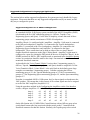
An example of the usage of “blocks” is an application typically handled by an AN/SIA114B. The AN/SIA-114B is capable of addressing 5 1MC announcing groups (Officers,
Topside, Crew, Engineering Spaces, and Spare). Since, in normal operating mode, all 5
15
of these 1MC groups is handled by the same half of an AM-2316 amplifier, obviously,
only one announcement can be made at a given time (although this announcement may be
routed to more than one of the announcing groups). If an announcement is in progress,
the 1MC busy line is activated which illuminated the corresponding lamp on any ICMSB/2 Mic Control Stations connected to the system.
The Integrated Announcing System duplicates this functionality by allowing only 1 Mic
Station access to a “block” at a given time. If the 5 1MC announcing groups mentioned
above were assigned to the groups in Block 1 (V1-V5, for instance), the Block 1 busy
line would be activated if an announcement was in progress on any of them, thus
prohibiting announcements from other Mic Stations to Block 1 until the announcement in
progress is complete (i.e. PTT is released).
To be more specific, if the Mic Control Station connected to Mic Interface 1 selects the
Officers, Topside, and Crew groups (V1, V2, and V3, respectively) to make an
announcement, Mic Control Stations connected to any other Mic Interface (2-16) would
be unable to access any of the 1MC groups (Officers, Topside, Crew, Engineering
Spaces, or Spare) until the announcement from Mic Interface 1 is complete and the 1MC
Busy lamp (Block 1 busy in this case) is extinguished.
Amplifier Configuration
As mentioned in the Voice Channel section above, each amplifier is configured for the
Alarm Channels and Voice Channels which are to be routed to it during normal system
operation. For example, Amplifier 1 (left-most amplifier in Amplifier Chassis 1) can be
configured in the following manner: A1, A2, V1. With such a configuration, Amplifier
1 would broadcast the Collision Alarm (A1) or the Chemical Alarm (A2) to the
loudspeakers connected to it if either one was activated. In addition, the audio on Voice
Channel 1 (i.e. the audio from any Mic Station connected with the group select switch
connected to the V1 line activated) would also be broadcast to the connected
loudspeakers. If either of the alarms were activated while a V1 announcement was in
progress, the alarm signal would override the voice announcement. If both of the alarm
were active simultaneously, the Collision Alarm (A1) would override the Chemical
Alarm (A2).
Amplifier Sparing (Amplifiers 6 & 12)
Each Amplifier Chassis in the system can be configured with an automatic spare
amplifier module (the spare must be in the right-most position in the chassis). The
chassis is configured for Sparing Mode by toggling the DIP-switch on the back of chassis
to the SPARE position (see Installation section for more information on setting DIPswitches). In addition, this amplifier (Amplifier 6 in Chassis 1 or Amplifier 12 in Chassis
2) should not be configured in the system and no loudspeakers should be connected to
these amplifier outputs on the Ship’s Wiring Board.
16
If a fault is detected in one of the amplifiers in the chassis (i.e. excessive temperature
fault, no output fault, no response fault, or amplifier-not-present fault), the spare
amplifier is automatically switched in for the amplifier with the fault. When the fault is
removed, the spare amplifier is placed back into standby mode.
If there are multiple amplifier faults in the chassis, the spare will be switched in for the
amplifier that is furthest to the left in the chassis.
This should be taken into consideration when deciding the position of each amplifier in
the chassis.
Configuring the Amplifiers via the User Interface
This section describes the procedure for entering the amplifier configurations into the
system using the User Interface.
First, make sure that the Main Menu (see top-most menu in Figure 1) is displayed on the
User Interface. If it is not, press the softkeys labeled Back or Esc until the Main Menu is
displayed.
From the Main Menu, press the softkey labeled Conf. As illustrated in Figure 1, the next
screen to be displayed is the Pin-Entry Screen. Use the Scroll Knob to change the
number of the first digit and, when the proper number is displayed, press the softkey
labeled > to advance to the next digit. After all digits are entered, press the softkey
labeled Enter. Entry of the proper PIN number should result in the Configuration Menu
being displayed.
The default PIN number for the system is 0000.
From the Configuration Menu, press the softkey labeled Amp to display the Amp
Configuration Menu. Using the Scroll Knob, select the number of the amplifier (1-12) to
configure and then press the softkey labeled Select.
The display should now read “Amp x” where x is the number of the amplifier selected to
configure. Using the Scroll Knob, select each Alarm Channel or Voice Channel to be
broadcast through the selected amplifier. After the desired Alarm Channel or Voice
Channel is shown, press the softkey labeled Enter.
Note that the first selection that appears when the scroll knob is turned is labeled “AL”.
If Enter is pressed while this selection is displayed, the selected amplifier will be
configured for all Alarm and Voice Channels.
After all entries have been made, press the softkey labeled Back. Use the softkey labeled
Clr to clear all Alarm/Voice Channels from the selected amplifier.
Note that the configuration information is stored in non-volatile memory and will be
retained even if power to the system is lost.
17
Configuring the Mic Station Priority via the User Interface
Each of the 16 possible Mic Stations has a priority configuration parameter that can be
adjusted via the User Interface. Configuring a Mic Station to HIGH priority will allow it
to override announcements that are in progress from a LOW priority Mic Station. Please
note that this overriding works for the entire Voice Channel “block”.
For example, assume that an announcement is in progress from LOW priority Mic Station
2 on Voice Channel V2. If Mic Station 1 is configured for HIGH priority and an
announcement is made from it on Voice Channel V1, remembering that V1 and V2 are
both part of Block 1, the announcement from Mic Station 1 will override (cut off) the
announcement from Mic Station 2. As soon as HIGH priority Mic Station 1 releases its
PTT, the announcement from Mic Station 2 will be allowed to resume.
To configure the Mic Stations from the User Interface, follow the procedure in the
previous section (Configuring the Amplifiers via the User Interface) to get to the
Configuration Menu. Use the Scroll Knob to access more selections on the Configuration
Menu, then press the softkey labeled Mic to display the Mic Station Configuration Menu.
Using the Scroll Knob, select the Mic Station (1-16) to configure and press the softkey
labeled Select.
The display should now read “Mic x” where x is the number of the Mic Station selected
to configure. Using the Scroll Knob, select either HI or LO priority for the selected Mic
Station and press the softkey labeled Enter.
Note that the configuration information is stored in non-volatile memory and will be
retained even if power to the system is lost.
Configuring the Alarm Generator via the User Interface
As described in the Integrated Announcing System Components section, the
Main/Amplifier Interface Module contains two redundant Alarm Generators. The user
has the ability to test either Alarm Generator (provided an alarm is not active) and can
also switch from one Alarm Generator to the other (even if an alarm is active).
Using the User Interface, the user can select which of the two Alarm Generators is
“active” (i.e. which Alarm Generator will be used to generate alarms for broadcast to the
system). To change the active Alarm Generator, follow the procedure in the Configuring
the Amplifiers via the User Interface section to get to the Configuration Menu. Press the
softkey labeled Agen to display the Alarm Generator Configuration Menu.
Using the Scroll Knob, select Alarm Generator 1 or 2 and press the softkey labeled
Select.
Note that the configuration information is stored in non-volatile memory and will be
retained even if power to the system is lost.
18
Changing the Pin Number via the User Interface
To change the PIN number required to access the Configuration Menu, follow the
procedure in the Configuring the Amplifiers via the User Interface section to get to the
Configuration Menu (obviously, the current PIN number must be known to change it).
The default PIN number for the system is 0000.
Use the Scroll Knob to access more selections on the Configuration Menu and press the
softkey labeled Pin to display the PIN Assignment Menu. Use the Scroll Knob to dial up
the number (0-9) for each digit and press the softkey labeled > to proceed to the next
digit. Press the softkey labeled Enter when the new 4-digit PIN number is complete.
19
Reviewing the System Configuration
Once the system is configured, it may be desirable to review the system configuration. This can
be accomplished by pressing the softkey labeled Review from the Main Menu (press the softkeys
labeled Back or Esc until the Main Menu is displayed).
The System Review Menu will then be displayed with the options Esc, Agen, and Amp.
Pressing the softkey labeled Agen will allow the user to see which Alarm Generator (1 or 2) is
set as the “active” generator (which will be used to generate system alarms if activated).
Pressing the softkey labeled Amp will allow the user to review an amplifier configuration. On
the Amp Selection Screen, use the Scroll Knob to select the amplifier (1-12) to review and press
the softkey labeled Select. The Amp Review Screen should then be displayed which shows
“Amp x:”, where x is the number of the selected amplifier, followed by a list of the Alarm
Channels and Voice Channels assigned to that amplifier.
If the Scroll Knob is rotated on the System Review Menu, additional options Esc and Mic will
be displayed. Press the softkey labeled Mic will allow the user to review a Mic Station
configuration. On the Mic Station Selection Screen, use the Scroll Knob to select a mic station
(1-16) to review and press the softkey labeled Select. The Mic Station Review Screen should
then be displayed which shows “Mic x:”, where x is the number of the selected Mic Station,
followed by HI or LO indicating the priority level assigned to that mic station.
20
Testing the System
The Integrated Announcing System has several self-test features built into it to provide
continuous, reliable operation. Several of the built-in test mechanisms are run automatically and
faults observed can be reported to the user immediately via the User Interface.
The Main/Amplifier Interface Module communicates periodically with each Amplifier Chassis in
an effort to determine system status. On the Main Menu of the User Interface, the total number
of system faults present is reported and the details each fault are displayed in a rotating fashion
(i.e. fault 1 is displayed for 1 second, the next fault is displayed for 1 second, eventually rotating
back to fault 1).
The fault messages that may be observed include the following:
Fault Message
Description
Bckpln x Not Present
Amp x Not In Slot
Amp x Communication
Error
Amp x Overload
Amp x Short
Amp x Ex. Temp
where x=1 or 2 indicating absence of communication with Bckpln x
where x=1-6 indicating no amplifier detected in Slot x
where x=1-6 indicating inability to communicate with amplifier in Slot x
(amplifier could be powered down)
where x=1-6 indicating an overload (load > 250W) detected on amplifier in Slot x
where x=1-6 indicating a short circuit detected on amplifier in Slot x
where x=1-6 indicating excessive temperature detected on amplifier in Slot x
Please note that an update to the displayed diagnostic messages may not occur immediately upon
changing an element in the system (i.e. powering up an amplifier, swapping out an amplifier,
etc.). In order to force an update to the diagnostics, press one of the softkeys to exit the Main
Menu, then press the softkey labeled Esc to return to the Main Menu.
Returning to the Main Menu forces the system to update the diagnostic messages.
Testing the Alarm Generators
The system also provides a way to test either Alarm Generator. Please note that testing
of either Alarm Generator can only be performed when there is no active alarm (i.e. no
alarm being broadcast).
To test an Alarm Generator, start at the Main Menu (press the softkeys labeled Back or
Esc until the Main Menu is displayed). On the Main Menu, press the softkey labeled
Test to enter the Test Menu. On the Test Menu, press the softkey labeled Agen to
display the Alarm Generator Test Selection screen. Use the Scroll Knob to select Alarm
Generator 1 or 2 and press the softkey labeled Select to display to Alarm Selection
screen. Use the Scroll Knob here to select the specific alarm signal (1-5) to test (i.e.
1=Collision, 2=Chemical, 3=General, 4=Unassigned, 5=Flight Crash) then press the
softkey labeled Select.
The selected alarm signal will then be generated by the selected Alarm Generator and
routed to the loudspeaker on the User Interface. In addition, the Bargraph display will
display the peak level of alarm signal. Verify that the peak level illuminates at least one
of the green LED’s. Press the softkey labeled Done to complete the testing of the Alarm
Generator.
21
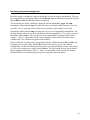
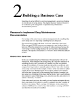
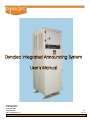
Testing the Amplifier Modules
Each Amplifier Module (60173-350) has 3 indicator lights (Figure 4 below) which
provide a general indication of the module’s status.
CPU
FAULT
FUSE
ON
POWER
OFF
Figure 4 : Amplifier Module Front Panel
The upper-most indicator light, labeled CPU, provides an indication that amplifier’s
microprocessor is running. When the unit is functioning normally, this indicator light
should flash on and off once per second. The middle indicator light, labeled FAULT,
provides an indication of the presence of any fault in the amplifier (the specific details of
the fault can be obtained using the Amplifier Test method described below). The bottommost indicator light, labeled FUSE, is an indication of the status of the fuse on the
Amplifier Module. If this indicator light is illuminated, the Amplifier Module fuse
should be replaced (note that the indicator light will be illuminated only when the
Amplifier Module is plugged into the Amplifier Chassis).
The system also provides a way to test each Amplifier Module in the system. When an
amplifier is tested, a test tone approximately 500ms in duration is generated and sent
through the amplifier (and to the loudspeakers connected to it). This test tone is used to
estimate the speaker load connected to the amplifier. After the approximate speaker load
is calculated, the User Interface displays the status of the tested amplifier along with the
approximate speaker load and heatsink temperature.
To test an Amplifier Module, start at the Main Menu (press the softkeys labeled Back or
Esc until the Main Menu is displayed). On the Main Menu, press the softkey labeled
Test to enter the Test Menu. On the Test Menu, press the softkey labeled Amp to
display the Amplifier Test Selection screen. Use the Scroll Knob to select an amplifier
module to test and press the softkey labeled Select to begin the test.
22
Auxiliary System Outputs
The system provides several auxiliary outputs that may be used for various functions.
Visual Indicator Output
This output is a 115VAC output signal provided from the Main/Amplifier Interface
Module that can be used to power incandescent visual indicators of the alarm activation
status. For alarm signals 1, 2, 4, and 5 (i.e. Collision Alarm, Chemical Alarm,
Unassigned Alarm, and Flight Crash Alarm, respectively), the 115VAC is switched on
continuously. For alarm signal 3 (General Alarm), the 115VAC is repeatedly switched
on for 300ms and off for 300ms.
Note that this 115VAC is switched via relay directly from the input power connector on
the Main/Amplifier Interface Module which is fused a 8A. This output signal can be
accessed on the Visual Out + and – terminals (2 pairs of terminals) on the Aux Signal
Interface connector on the Ship’s Wiring Board.
The maximum visual indicator load is 7.5A
Entertainment System Attenuate
If a separate Entertainment System is used, it is usually desirable to attenuate the volume
of its audio when a 1MC (Block 1) announcement is in progress. The Entertainment
System Attenuate signal (accessible at the Ent. Sys. Atten + and – terminals on the Aux
Signal Interface connector of the Ship’s Wiring Board) is an isolated contact closure
which can be connected to the Entertainment System to trigger the desired attenuation.
The ratings on this contact closure are 60V, 400mA MAX
Entertainment System Mute
If a separate Entertainment System is used, it is usually desirable to mute its audio when
an alarm signal is active. The Entertainment System Mute signal (accessible at the Ent.
Sys. Mute + and – terminals on the Aux Signal Interface connector of the Ship’s Wiring
Board) is an isolated contact closure which can be connected to the Entertainment System
to trigger the desired muting.
The ratings on this contact closure are 60V, 400mA MAX
Alarm Active
This is an isolated contact closure which is identical in function to the Entertainment
System Mute signal. It simply provides a way to inform an auxiliary piece of equipment
that an announcing system alarm is in progress. This signal is accessible at the Alarm
Active + and – terminals on the Aux Signal Interface connector of the Ship’s Wiring
Board.
The ratings on this contact closure are 60V, 400mA MAX
23
Alarm Operation
Alarms are generated by the Alarm Generator configured to be the “active” generator (see the
Configuring the Alarm Generator via the User Interface section on page 18).
Each alarm, with the exception of the General alarm, will remain active for the duration in which
a contactor connected to the corresponding terminals on P33 is in the active position. The
General Alarm is activated for 15-second intervals. For example, if a General Alarm contactor is
activated momentarily and then de-activated, the General Alarm will still sound for 15 seconds
from the time that the contactor was activated. If a General Alarm contactor is activated for 16
seconds before being de-activated, the General Alarm will sound for a total of 30 seconds from
the time that the contactor was activated.
See the Installation section for details on connecting alarm contactors to the system.
PBX Interface Operation
If the system is configured with a PBX/IVCS Modem Interface Module (60173-445), up to 6
analog (POTS) phone lines can be connected to the system for making 1MC (Block 1)
announcements through a PBX. The PBX interface is pre-configured to duplicate the
functionality of the IVCS Modem from the perspective of which announcing groups are selected
when a phone call is placed into each line.
The system is configured for the following:
Phone Line called in to
1
Announcing Groups activated
All Call (V1 – V6 activated)
(connected to P35 terminals 1 and 2)
2
V2, V3, V4, V5, and V6
(connected to P35 terminals 3 and 4)
3
V4 and V5
(connected to P35 terminals 5 and 6)
4
V6
(connected to P35 terminals 7 and 8)
5
V3
(connected to P35 terminals 9 and 10)
6
V1
(connected to P35 terminals 11 and 12)
If Block 1 is busy when a call is placed into any of the 6 line interfaces, the user will receive a
busy signal. For this reason, only one call can be placed at a time through the PBX interface. If
an announcement is in progress through one of the 6 line interfaces and a different user attempts
to call that or any other line, the user will receive a busy signal.
See the Installation section for details on connecting analog phone lines to the system.
24
IVCS Modem Interface Operation
If the system is configured with a PBX/IVCS Modem Interface Module (60173-445),
connections can be made to a Modified IVCS Modem (62300-127-1) for making announcements
through an AN/STC-2 switchboard. Note that the modification to the standard 62300-127
involves the diode reversal which was necessary to allow the IVCS Modem to function correctly
with the AN/SIA-114B system.
The IVCS modem operates in a fashion very similar to that described in the PBX Interface
Operation section on the previous page. Six phone lines from an AN/STC-2 switchboard can be
connected to the IVCS Modem. If a call is received on one of the lines, the IVCS Modem
activates the appropriate relays to activate one or more 1MC (Block 1) announcing groups. The
default setup for the IVCS Modem is for the group selections shown on the table in the PBX
Interface Operation section on the previous page although this configuration can be changed with
the addition or removal of diodes.
The Integrated Announcing System provides power to and interprets the signaling from the
IVCS Modem to determine which announcing groups are being activated. The IVCS Modem
incorporates a relay which provides a busy closure to indicate if 1MC (Block 1) is busy. This
relay is controlled by circuitry in the PBX/IVCS Modem Interface Module and is configured to
be activated when Block 1 is busy.
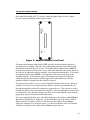
A DIP-switch setting internal to the PBX/IVCS Modem Interface Module can be changed so this
busy relay is activated when a block other than Block 1 is busy. The figure below indicates the
position of this DIP-switch on the PBX/IVCS Modem Interface Module PCB assembly (60173440).
Figure 5 : PBX/IVCS Modem PCB Detail showing Modem Busy Select DIP-switch
25
Suggested Configurations for Legacy-type Applications
The sections below outline suggested configurations for systems previously handled by Legacy
equipment. Please note that these are only suggested configurations and, by no means, are the
only way to configure the system.
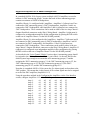
Suggested Configuration for an AN/SIA-114B Application
In a standard AN/SIA-114B Legacy system, one half of the AM-2316 amplifier (500W)
is dedicated to the five 1MC announcing groups (i.e. Officers, Topside, Crew,
Engineering Spaces, and Spare). For the sake of simplicity, assume that each of these
announcing groups contains a maximum of 250W of loudspeakers.
Amplifier Chassis 1 is configured with 6 amplifiers: Amplifier 1 (left-most) is connected
to the Officers loudspeakers, Amplifier 2 is connected to the Topside loudspeakers,
Amplifier 3 is connected to the Crew loudspeakers, Amplifier 4 is connected to the
Engineering Spaces loudspeakers, and Amplifier 5 is connected to the Spare
loudspeakers. These connections can be made at either of the two Amp Chassis 1
Outputs Euroblock connectors on the Ship’s Wiring Board. Amplifier 6 (right-most) is
configured as a spare (by placing the DIP-switch on the rear of Amplifier Chassis 1 in the
SPARE position) for the five 1MC amplifiers and, as mentioned in the Amplifier Sparing
section, no connections should be made to the Amp 6 Out terminals on the abovementioned Euroblock connector.
As described in the Voice Channel “Blocks” section, these 5 announcing groups (i.e.
Officers, Topside, Crew, Engineering Spaces, and Spare) should be assigned to 5 of the
Voice Channels in Block 1 (since Block 1 is the only block in the default system large
enough to accommodate 5 announcing groups). Consider assigning the Officers
announcing group to V1, the Topside announcing group to V2, the Crew announcing
group to V3, the Engineering Spaces announcing group to V4, and the Spare announcing
group to V5.
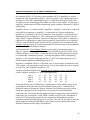
Note that, in a standard AN/SIA-114B system, the five alarm signals are broadcast to the
1MC speakers. This means that, in this system, all five alarm signals need to be assigned
to each of the 1MC amplifiers (Amplifiers 1-5).
Using the procedure outlined in the Configuring the Amplifiers via the User Interface
section, configure Amplifiers 1-5 in the following manner:
Amp 1:
Amp 2:
Amp 3:
Amp 4:
Amp 5:
A1
A1
A1
A1
A1
A2
A2
A2
A2
A2
A3
A3
A3
A3
A3
A4
A4
A4
A4
A4
A5
A5
A5
A5
A5
V1
V2
V3
V4
V5
On the Mic Station side, IC/MSB-2 Mic Control Stations with an Officers group select
switch should connect the line associated with that switch to the V1 terminal on the
Euroblock connector for that Mic Station. Similarly, the Topside group select switch
26
should be connected to the V2 terminal, the Crew group select switch should be
connected to the V3 terminal, the Engineering Spaces group select switch should be
connected to the V4 terminal, and the Spare group select switch should be connected to
the V5 terminal. If an IC/MJB-2 Jackbox or M-136A/SIC Microphone is used, the PTT
line should be jumpered to the terminal on the Euroblock connector associated with the
announcing group to be accessed. The 1MC BUSY lamp on each mic station should be
connected to the Block 1 busy signal on the associated Mic Station Euroblock connector
on the Ship’s Wiring Board.
With the configuration outlined above, a Mic Station selecting the Officers group select
switch will have its audio routed to the input of Amplifier 1 (the Officers amplifier) to be
broadcast to the Officers loudspeakers. If more than one group is selected at a Mic
Station, the audio from that mic station will be routed to all of the amplifiers associated
with the selected groups.
The configuration above also routes any active alarm to all five 1MC amplifiers and an
active alarm will override a voice announcement in progress on any of the amplifiers. If
multiple alarms are active, only the highest priority alarm will be broadcast.
In a standard AN/SIA-114B system, the other half of the AM-2316 amplifier (500W) is
dedicated to 6MC (Bullhorn) announcing. Assume that 500W is needed for the 6MCannouncing group in this system.
Amplifier Chassis 2 is configured with 3 amplifiers: Amplifier 7 (left-most) is for one
half of the 500W 6MC load and Amplifier 8 is for the second half. These connections
can be made at either of the two Amp Chassis 2 Outputs Euroblock connectors on the
Ship’s Wiring Board. Amplifier 12 (right-most) is configured as a spare (by placing the
DIP-switch on the rear of Amplifier Chassis 2 in the SPARE position) for the 6MC
amplifiers and, as mentioned in the Amplifier Sparing section, no connections should be
made to the Amp 12 Out terminals on the above-mentioned Euroblock connector.
Since the 6MC system operates independently from the other announcing groups, little
concern is needed for where the 6MC Voice Channel is placed in terms of priority.
Consider using V9 (which is the only Voice Channel in Block 3) for 6MC
announcements.
In a standard AN/SIA-114B system, none of the alarms are broadcast to the 6MC
speakers. So, using the procedure outlined in the Configuring the Amplifiers via the User
Interface section, configure Amplifiers 7 and 8 in the following manner:
Amp 7:
Amp 8:
V9
V9
On the Mic Station side, IC/MSB-2 Mic Control Stations with a Bullhorn group select
switch should connect the line associated with that switch to the V9 terminal on the
Euroblock connector for that Mic Station. The 6MC BUSY lamp on each mic station
should be connected to the Block 3 busy signal on the associated Mic Station Euroblock
connector on the Ship’s Wiring Board.
27
Suggested Configuration for an AN/SIA-117B Application
In a standard AN/SIA-117B Legacy system, multiple AM-2316 amplifiers are used to
address four 1MC announcing groups (i.e. Officers, Topside, Crew, Engineering Spaces,
and Spare), 2 1MC/3MC announcing groups (i.e. Flight Deck and Hangar Deck), and 2
“Emergency Alert” announcing groups which only receive alarm signals. For the sake of
simplicity, assume that each of these announcing groups contains a maximum of 250W of
loudspeakers.
Amplifier Chassis 1 is configured with 5 amplifiers: Amplifier 1 (left-most) is connected
to the Officers loudspeakers, Amplifier 2 is connected to the Topside loudspeakers,
Amplifier 3 is connected to the Crew loudspeakers, and Amplifier 4 is connected to the
Engineering Spaces loudspeakers. These connections can be made at either of the two
Amp Chassis 1 Outputs Euroblock connectors on the Ship’s Wiring Board. Amplifier 6
(right-most) is configured as a spare (by placing the DIP-switch on the rear of Amplifier
Chassis 1 in the SPARE position) for the four 1MC amplifiers and, as mentioned in the
Amplifier Sparing section, no connections should be made to the Amp 6 Out terminals on
the above-mentioned Euroblock connector.
As described in the Voice Channel “Blocks” section, these 4 announcing groups (i.e.
Officers, Topside, Crew, and Engineering Spaces) should be assigned to 4 of the Voice
Channels in Block 1 (since Block 1 is the only block in the default system large enough
to accommodate 4 announcing groups). Consider assigning the Officers announcing
group to V1, the Topside announcing group to V2, the Crew announcing group to V3,
and the Engineering Spaces announcing group to V4.
Note that, in a standard AN/SIA-117B system, the five alarm signals are broadcast to the
1MC speakers. This means that, in this system, all five alarm signals need to be assigned
to each of the 1MC amplifiers (Amplifiers 1-4).
Using the procedure outlined in the Configuring the Amplifiers via the User Interface
section, configure Amplifiers 1-4 in the following manner:
Amp 1:
Amp 2:
Amp 3:
Amp 4:
A1
A1
A1
A1
A2
A2
A2
A2
A3
A3
A3
A3
A4
A4
A4
A4
A5
A5
A5
A5
V1
V2
V3
V4
On the Mic Station side, IC/MSB-2 Mic Control Stations with an Officers group select
switch should connect the line associated with that switch to the V1 terminal on the
Euroblock connector for that Mic Station. Similarly, the Topside group select switch
should be connected to the V2 terminal, the Crew group select switch should be
connected to the V3 terminal, and the Engineering Spaces group select switch should be
connected to the V4 terminal. If an IC/MJB-2 Jackbox or M-136A/SIC Microphone is
used, the PTT line should be jumpered to the terminal on the Euroblock connector
associated with the announcing group to be accessed. The 1MC BUSY lamp on each mic
station should be connected to the Block 1 busy signal on the associated Mic Station
Euroblock connector on the Ship’s Wiring Board.
28
With the configuration outlined above, a Mic Station selecting the Officers group select
switch will have its audio routed to the input of Amplifier 1 (the Officers amplifier) to be
broadcast to the Officers loudspeakers. If more than one group is selected at a Mic
Station, the audio from that mic station will be routed to all of the amplifiers associated
with the selected groups.
The configuration above also routes any active alarm to all five 1MC amplifiers and an
active alarm will override a voice announcement in progress on any of the amplifiers. If
multiple alarms are active, only the highest priority alarm will be broadcast.
The standard AN/SIA-117B system also accommodates two 1MC/3MC announcing
groups (i.e. Flight Deck and Hangar Deck groups). These two groups receive the
corresponding 3MC announcements from Mic Stations selecting the Flight Deck or
Hangar Deck groups. However, any 1MC announcement in progress overrides the 3MC
announcement at these loudspeakers. For the sake of simplicity, assume that each of
these 3MC announcing groups contains a maximum of 250W of loudspeakers.
Amplifier Chassis 2 will consist of 4 amplifiers. Amplifier 7 (left-most) is connected to
the Flight Deck loudspeakers, Amplifier 8 is connected to the Hangar Deck loudspeakers,
and Amplifier 9 is connected to the Emergency Alert loudspeakers (see section below).
These connections can be made at either of the two Amp Chassis 2 Outputs Euroblock
connectors on the Ship’s Wiring Board. Amplifier 12 (right-most) is configured as a
spare (by placing the DIP-switch on the rear of Amplifier Chassis 2 in the SPARE
position) for Amplifiers 7-9 and, as mentioned in the Amplifier Sparing section, no
connections should be made to the Amp 12 Out terminals on the above-mentioned
Euroblock connector.
In this case, the 2 announcing groups (i.e. Flight Deck and Hangar Deck) should be
assigned to the 2 Voice Channels in Block 2 (Block 2 consists of Voice Channels V7 and
V8). Consider assigning the Flight Deck announcing group to V7 and the Hangar Deck
announcing group to V8.
Note that, in a standard AN/SIA-117B system, the five alarm signals are also broadcast to
these 1MC/3MC speakers. This means that, in this system, all five alarm signals need to
be assigned to each of the 1MC/3MC amplifiers (Amplifiers 7 & 8).
Using the procedure outlined in the Configuring the Amplifiers via the User Interface
section, configure Amplifiers 7 & 8 in the following manner:
Amp 7:
Amp 8:
A1
A1
A2
A2
A3
A3
A4
A4
A5
A5
V1
V1
V2
V2
V3
V3
V4
V4
V7
V8
On the Mic Station side, IC/MSB-2 Mic Control Stations with a Flight Deck group select
switch should connect the line associated with that switch to the V7 terminal on the
Euroblock connector for that Mic Station. Similarly, the Hangar Deck group select
switch should be connected to the V8 terminal. If an IC/MJB-2 Jackbox or M-136A/SIC
Microphone is used, the PTT line should be jumpered to the terminal on the Euroblock
connector associated with the announcing group to be accessed. The 3MC BUSY lamp
on each mic station should be connected to the Block 2 busy signal on the associated Mic
Station Euroblock connector on the Ship’s Wiring Board.
29
With the configuration outlined above, a Mic Station selecting the Flight Deck group
select switch will have its audio routed to the input of Amplifier 7 (the Flight Deck
amplifier) to be broadcast to the Flight Deck loudspeakers. If more than one group is
selected at a Mic Station, the audio from that mic station will be routed to all of the
amplifiers associated with the selected groups. If a 1MC announcement is activated, it
will override a 3MC announcement in progress at these loudspeaker groups (since the
1MC Voice Channels [V1-V4] are higher priority than the 3MC Voice Channels [V7 &
V8]). This configuration also routes any active alarm to both 1MC/3MC amplifiers and
overrides any voice announcement in progress on any of the amplifiers. If multiple
alarms are active, only the highest priority alarm will be broadcast.
This leaves Amplifier 9 to configure. In the AN/SIA-117B, the Emergency Alert
loudspeakers are placed amongst the 1MC Officers and Crew loudspeakers to provide
emphasis in the event of an alarm signal. More specifically, these loudspeakers only
broadcast alarm signals.
Using the procedure outlined in the Configuring the Amplifiers via the User Interface
section, configure Amplifier 9 in the following manner:
Amp 9:
A1
A2
A3
A4
A5
With this configuration, any active alarm will be routed to the Emergency Alert
loudspeakers connected to Amplifier 9.
30
Suggested Configuration for an AN/SIA-118A Application
In a standard AN/SIA-118A Legacy system, multiple AM-2316 amplifiers are used to
address six 5MC announcing groups. Assume that each of these announcing groups
contains a maximum of 500W of loudspeakers.
Amplifier Chassis 1 is configured with 6 amplifiers: Amplifiers 1 (left-most) and 2 are
connected to 5MC announcing group 1 (5MC1) loudspeakers, Amplifiers 3 and 4 are
connected to 5MC2 loudspeakers, and Amplifiers 5 and 6 (right-most) are connected to
5MC3 loudspeakers. These connections can be made at either of the two Amp Chassis 1
Outputs Euroblock connectors on the Ship’s Wiring Board. Amplifier 6 (right-most) is
configured as an independent amplifier in this configuration (by placing the DIP-switch
on the rear of Amplifier Chassis 1 in the NO SPARE position).
Amplifier Chassis 2 is also configured with 6 amplifiers: Amplifiers 7 (left-most) and 8
are connected to 5MC announcing group 4 (5MC4) loudspeakers, Amplifiers 9 and 10
are connected to 5MC5 loudspeakers, and Amplifiers 11 and 12 (right-most) are
connected to 5MC6 loudspeakers. These connections can be made at either of the two
Amp Chassis 2 Outputs Euroblock connectors on the Ship’s Wiring Board. Amplifier 12
(right-most) is configured as an independent amplifier in this configuration (by placing
the DIP-switch on the rear of Amplifier Chassis 2 in the NO SPARE position).
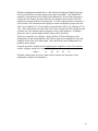
As described in the Voice Channel “Blocks” section, these 6 announcing groups should
be assigned to the 6 Voice Channels in Block 1 (since Block 1 is the only block in the
default system large enough to accommodate all 6 announcing groups). Consider
assigning the 5MC1 announcing group to V1, the 5MC2 announcing group to V2, the
5MC3 announcing group to V3, the 5MC4 announcing group to V4, the 5MC5
announcing group to V5, and the 5MC6 announcing group to V5.
Note that, in a standard AN/SIA-118A system, the five alarm signals are broadcast to the
5MC speakers. This means that, in this system, all five alarm signals need to be assigned
to each of the 5MC amplifiers (Amplifiers 1-12).
Using the procedure outlined in the Configuring the Amplifiers via the User Interface
section, configure Amplifiers 1-12 in the following manner:
Amp 1:
Amp 2:
Amp 3:
Amp 4:
Amp 5:
Amp 6:
Amp 7:
Amp 8:
Amp 9:
Amp 10:
Amp 11:
Amp 12:
A1
A1
A1
A1
A1
A1
A1
A1
A1
A1
A1
A1
A2
A2
A2
A2
A2
A2
A2
A2
A2
A2
A2
A2
A3
A3
A3
A3
A3
A3
A3
A3
A3
A3
A3
A3
A4
A4
A4
A4
A4
A4
A4
A4
A4
A4
A4
A4
A5
A5
A5
A5
A5
A5
A5
A5
A5
A5
A5
A5
V1
V1
V2
V2
V3
V3
V4
V4
V5
V5
V6
V6
31
On the Mic Station side, IC/MSB-2 Mic Control Stations with a 5MC1 group select
switch should connect the line associated with that switch to the V1 terminal on the
Euroblock connector for that Mic Station. Similarly, the 5MC2 group select switch
should be connected to the V2 terminal, the 5MC3 group select switch should be
connected to the V3 terminal, the 5MC4 group select switch should be connected to the
V4 terminal, the 5MC5 group select switch should be connected to the V5 terminal, and
the 5MC6 group select switch should be connected to the V6 terminal. If an IC/MJB-2
Jackbox or M-136A/SIC Microphone is used, the PTT line should be jumpered to the
terminal on the Euroblock connector associated with the announcing group to be
accessed. The 5MC BUSY lamp on each mic station should be connected to the Block 1
busy signal on the associated Mic Station Euroblock connector on the Ship’s Wiring
Board.
With the configuration outlined above, a Mic Station selecting the 5MC1 group select
switch will have its audio routed to the input of Amplifier 1 (the 5MC1 amplifier) to be
broadcast to the 5MC1 loudspeakers. If more than one group is selected at a Mic Station,
the audio from that mic station will be routed to all of the amplifiers associated with the
selected groups. This configuration also routes any active alarm to all 5MC amplifiers
and overrides any voice announcement in progress on any of the amplifiers. If multiple
alarms are active, only the highest priority alarm will be broadcast.
32
Parts Lists
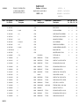
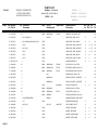
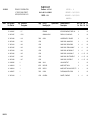
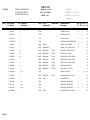
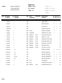
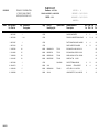
Top Level System Parts List
This section contains the parts list for the 60173-200-01 Integrated Announcing System
rack configuration. This configuration consists of the following system components:
(1) Ship’s Wiring Tray (Assembly A1)
(1) Main/Amp Interface Module (Assembly A2)
(3) Mic Interface Modules (Assemblies A3, A4, and A11)
(1) PBX/IVCS Modem Interface Module (Assembly A5)
(2) Amplifier Chassis with 12 Amp Modules each (Assemblies A6 and A12)
(2) Fan Trays (Assemblies A8 and A9)
(1) Auxiliary Amp Interface Module (Assembly A13)
Depending on the configuration of each particular system, some or all of these
components may or may not be included in the top-level system parts list.
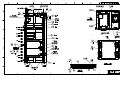
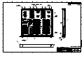
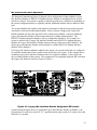
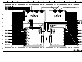
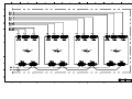
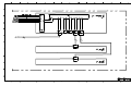
Please refer to Figures 6, 7, and 8 for locations of each of the components shown on the
following parts list.
33
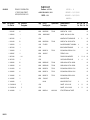
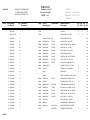
PARTS LIST
DYNALEC CORPORATION
87,WEST MAIN STREET
SODUS,NEW YORK 14551
11/01/2001
Notes Find Dynalec
No Part No
PAGE 1
Qty Reference
Designator
Enditem : 60173-200-01
REVLTR :
A
REVDATE : 09/14/2001
ORIGDATE : 09/14/2001
MANUF# :
RACK ASSY, 12A, 2AC, 3M, 1P
CAGE : 12763
Cage
Part Or
Identifying No
Specification
Nomenclature Or
Description
Dw
Sz
Dwg
Rev
Bd
Cd
Pt
Cd
1 60173-205
1
12763
ENCLOSURE ASSEMBLY
X
B
62
2 60173-206
2
12763
RAIL FRONT LEFT
X
A
69
3 60173-208
2
12763
RAIL REAR
X
A
69
4 60173-207
2
12763
RAIL MID
X
A
69
5 60173-209-01
2
12763
BLANK PANEL 1RU
X
A
69
6 60173-243
1
12763
PANEL, ACCESS
X
A
69
7 60173-244
1
12763
ENCLOSURE, FILTER
X
A
62
8 60173-212
1
12763
ACCESS PANEL I/O
X
A
69
9 60173-213
4
12763
ACCESS PANEL, LOUVERED SIDES
X
A
62
10 60173-214
2
12763
ACCESS PANEL, SIDE
X
A
69
11 60173-215
8
12763
SCREEN, ACCESS PANEL
X
A
69
12 60173-216
48
12763
RETAINER, ACCESS PNL
X
A
69
14 60173-217-02
2
12763
CHASSIS SUPPORT I/F
X
A
62
15 60173-218
8
12763
CHASSIS SUPPORT, 1RU SHORT
X
A
69
16 60173-219
4
12763
CHASSIS SUPPORT, 2RU LONG
X
A
69
18 60173-221
8
12763
CHASSIS SUPPORT, CARD CAGE
X
A
62
21 60173-224-01
6
12763
CABLE BAR, LONG
X
A
69
23 60173-227
1
12763
DOOR SUPPORT, 1RU
X
A
62
24 60173-228
1
12763
DOOR
X
A
62
25 60173-229
1
12763
GASKET, DOOR
X
A
69
26 60173-230-01
1
12763
HINGE, RACK, TOP
X
A
62
27 60173-230-02
1
12763
HINGE, RACK, BOTTOM
X
A
62
28 60173-231
2
12763
HINGE, DOOR
X
A
69
29 60173-232
3
12763
SCREW, DOOR
X
A
69
30 60173-233
1
12763
BRACKET, DOOR
X
A
62
31 60173-234
1
12763
SLIDE, DOOR
X
A
62
PARTS LIST
DYNALEC CORPORATION
87,WEST MAIN STREET
SODUS,NEW YORK 14551
11/01/2001
Notes Find Dynalec
No Part No
PAGE 2
Qty Reference
Designator
32 60173-235
1
34 60173-236
2
35 60173-435
1
36 60173-241
1
37 60173-415
1
38 60173-425
Enditem : 60173-200-01
RACK ASSY, 12A, 2AC, 3M, 1P
CAGE : 12763
Cage
Part Or
Identifying No
Specification
REVLTR :
A
REVDATE : 09/14/2001
ORIGDATE : 09/14/2001
MANUF# :
Nomenclature Or
Description
Dw
Sz
Dwg
Rev
Bd
Cd
Pt
Cd
12763
BRACE, DOOR
X
A
69
A8,A9
12763
FAN TRAY ASSEMBLY
X
A
60
A1
12763
SHIPS WIRING TRAY ASSEMBLY
X
A
60
12763
FRONT PANEL, 6RU I/F ACCESS
X
A
62
A2
12763
MAIN AMP I/F ASSEMBLY
X
A
60
3
A3,A4,A11
12763
MIC I/F ASSEMBLY
X
A
60
39 60173-445
1
A5
12763
PBX/ENT/IVCS I/F ASSEMBLY
X
A
60
40 60173-300
2
A6,A12
12763
CHASSIS ASSEMBLY, AMPLIFIER
X
A
60
41 60173-209-02
1
12763
BLANK PANEL 2RU
X
A
69
43 60173-350
12
12763
AMPLIFIER MODULE, 250 W
X
A
60
44 14108-045
1
FILTER, LINE, 55A
X
47 12203-006
45
96906
MS35338-139
FF-W-84
WSHR,LOCK 1/4
69
48 12211-010
45
96906
MS15795-810
FF-W-92
WSHR,FLAT 1/4,.625 OD .065 THK
69
FL1
FN 350-55/33
69
49 12145-004
20
96906
MS35307-305
FF-S-85
SCR,MACH-HEXHD 1/4-20 X 5/8
69
50 12130-003
136
96906
MS51957-45
FF-S-92
SCR,MACH-PNH,XREC 8-32 X 1/2
69
51 12203-004
139
96906
MS35338-137
FF-W-84
WSHR,LOCK #8 .040 THK
69
52 12211-007
135
96906
MS15795-807
FF-W-92
WSHR,FLAT #8 .375 OD .049 THK
69
53 60173-239
42
54 12211-003
104
96906
MS15795-803
FF-W-92
WSHR,FLAT #4 .250 OD .022 THK
69
55 12203-002
104
96906
MS35338-135
FF-W-84
WSHR,LOCK #4 .025 THK .209 DIA
69
56 12301-002
96
96906
MS35649-244
FF-N-836
NUT,PL,HEX 4-40 .093 THK
69
57 14212-004
3
96906
MS16633-4025
MIL-R-21248
RTNG RING .250SH, .210G, .029W
69
58 12205-006
3
96906
MS51859-6
WSHR,FLAT PLASTIC 1/4
69
59 12667-003
68
96906
MS24693-C272
FF-S-92
SCR,MACH-FLH,XREC 10-32 X 1/2
69
62 12140-003
7
96906
MS51958-63
FF-S-92
SCR,MACH-PNH,XREC 10-32 X 1/2
69
63 12203-005
36
96906
MS35338-138
FF-W-84
WSHR,LOCK #10 .34OD, .05T
69
HW-200
PANEL SCREW 10-32 X 5/8
X
69
PARTS LIST
DYNALEC CORPORATION
87,WEST MAIN STREET
SODUS,NEW YORK 14551
11/01/2001
Notes Find Dynalec
No Part No
PAGE 3
Qty Reference
Designator
64 12211-008
15
66 60173-470
4
W1,W4,W7,W18
67 60173-471
8
W2,W3,W5,W6,W8,W9,W19,W20
68 60173-472
1
69 60173-473
Enditem : 60173-200-01
RACK ASSY, 12A, 2AC, 3M, 1P
CAGE : 12763
REVLTR :
A
REVDATE : 09/14/2001
ORIGDATE : 09/14/2001
MANUF# :
Cage
Part Or
Identifying No
Specification
Nomenclature Or
Description
96906
MS15795-808
FF-W-92
WSHR,FLAT #10 .438 OD, .05T
AK129-2
Dw
Sz
Dwg
Rev
Bd
Cd
Pt
Cd
69
CABLE ASSY, RACK, MIC I/F
X
12763
CABLE ASSY, RACK, SWB I/F
X
A
W10
12763
CABLE ASSY, RACK, AUX SIG I/F
X
A
C2
60
2
W11,W21
12763
CABLE ASSY, RACK, AMP SIG I/F
X
A
C2
60
70 60173-474
1
W12
12763
CABLE ASSY, RACK, SERIAL I/F
X
A
C2
60
71 60173-475
1
W13
12763
CABLE ASSY, RACK, AN. BUS
X
A
69
72 60173-476
1
W14
12763
CABLE ASSY, RACK, DIG. BUS
X
A
69
73 60173-217-03
4
12763
CHASSIS SUPPORT I/F
X
A
62
74 12301-005
58
96906
MS35650-304
FF-N-836
NUT,PL,HEX 10-32 .125 THK
69
76 12667-005
2
96906
MS24693-C274
FF-S-92
SCR,MACH-FLH,XREC.190-32 X .75
69
77 12140-004
10
96906
MS51958-64
FF-S-92
SCR,MACH-PNH,XREC 10-32 X 5/8
69
79 60173-252
3
B-14
SPRING,OD.343, ID.253, 1"LG
69
80 60173-250
2
HM06500-3A
HELICAL ISOLATOR, 1/2 WIRE RP
X
69
81 60173-251
4
HM06500-4A
HELICAL ISOLATOR, 1/2 WIRE RP.
X
69
82 60173-242
3
12763
MTG PLATE, ISOLATOR
X
83 12184-009
24
96906
MS51960-88
84 12149-009
24
96906
MS35308-312
85 60173-257
1
39428
88 14155-104
1
4INCHES REQUIRED
89 60173-482
1
A7
90 15059-035
3
W15-W17
91 60173-260
4
92 60173-261
QQ-A-200/8
69
A
69
69
SCREW 1/4-28 X 1 1/2 FH PHL
69
SCR,CAP,HEX 1/4-28 X 1-1/2
69
90298A574
SCREW, SHOULDER 5/16 X 1/4-20
69
GEE98-C
GROMMET EDGIN 071-098 V 100FT
69
FF-S-92
12763
DISTRIBUTION BOX ASSY
X
60
CORD, POWER, IEC 4FT.
X
69
12763
GASKET, SIDE PANEL
X
A
69
2
12763
GASKET, SIDE PANEL
X
A
69
93 60173-262
1
12763
GASKET, ACCESS PANEL
X
A
69
94 60173-263
1
12763
GASKET, FILTER PANEL
X
A
69
C3C-C2-2-
18/3SVT-4FT
PARTS LIST
DYNALEC CORPORATION
87,WEST MAIN STREET
SODUS,NEW YORK 14551
11/01/2001
Notes Find Dynalec
No Part No
PAGE 4
Qty Reference
Designator
Enditem : 60173-200-01
RACK ASSY, 12A, 2AC, 3M, 1P
CAGE : 12763
REVLTR :
A
REVDATE : 09/14/2001
ORIGDATE : 09/14/2001
MANUF# :
Cage
Part Or
Identifying No
Specification
Nomenclature Or
Description
Dw
Sz
Dwg
Rev
Bd
Cd
Pt
Cd
95 66501-162
4
96906
MS51937-3C
MS51937
EYEBOLT 3/8-16
69
96 12211-015
6
96906
MS15795-815
FF-W-92
WSHR,FLAT 3/8 1.000 OD
69
97 12203-008
5
96906
MS35338-141
FF-W-84
WSHR,LOCK 3/8
69
98 12301-008
5
96906
MS51971-3
FF-N-836
NUT,PL,HEX 3/8-16 .330 THK
69
99 12119-002
1
96906
MS51957-28
FF-S-92
SCR,MACH-PNH,XREC 6-32 X 3/8
69
100 12301-003
1
96906
MS35649-264
FF-N-836
NUT,PL,HEX 6-32 .108 THK
69
101 12203-003
4
96906
MS35338-136
FF-W-84
WSHR,LOCK #6 .031 THK .250 DIA
69
102 12211-005
2
96906
MS15795-805
FF-W-92
WSHR,FLAT #6
69
103 60173-264
1
12763
MIL-P-15024
IDENTIFICATION PLATE
X
A
69
104 66729-028
1
12763
ORDALT PLATE
X
-
69
105 12108-001
8
96906
MS51957-13
FF-S-92
SCR,MACH-PNH,XREC 4-40 X 1/4
69
106 12165-007
1
96906
MS35308-360
FF-S-92
SCR,MACH-HEX 3/8-24 X 1
69
107 12301-004
7
96906
MS35649-284
FF-N-836
NUT,PL,HEX 8-32 .125 THK
69
108 66729-045
1
12763
109 14128-044
1
06383
110 60173-484
1
12763
111 14117-020
1
86797
112 12306-006
1
113 12301-006
1
114 60173-455
1
A13
115 60173-477
1
W22
96906
.312 OD
CARD HOLDER
TM3S10
SIGMA-10ST
MS35649-2254
12763
AK137-2
X
A
69
TIE MOUNT #10
FF-N-836
69
JUMPER LIST, INPUT POWER
X
KNOB,CLAMP,1/4-20 X 1.0"LG BLK
X
A
J1
60
69
NUT, ACORN, 1/4-20 NICK PLATE
69
NUT,PL,HEX 1/4-20 .185 THK
69
AMP I/F ASSEMBLY
X
CABLE, RACK AMP CHASSIS
X
A
60
69
Ship’s Wiring Module Parts List
This section contains the parts list for the 60173-435 Ship’s Wiring Module. This
module includes the Ship’s Wiring Module PCB Assembly (60173-430) and all of its
associated components.
Please refer to Figure 9 for locations of each of the components shown on the following
parts list.
41
PARTS LIST
DYNALEC CORPORATION
87,WEST MAIN STREET
SODUS,NEW YORK 14551
01/31/2002
Notes Find Dynalec
No Part No
PAGE 1
Qty Reference
Designator
REVLTR :
Enditem : 60173-435
A
REVDATE : 09/13/2001
ORIGDATE : 09/13/2001
MANUF# :
SHIPS WIRING TRAY ASSEMBLY
CAGE : 12763
Cage
Part Or
Identifying No
Specification
Nomenclature Or
Description
Dw
Sz
Dwg
Rev
Bd
Cd
Pt
Cd
1 60173-237-01
1
12763
FRONT PANEL, SHIPS WIRING TRAY
X
A
62
2 60173-436
1
12763
I/F TRAY
X
B
62
3 60173-430
1
12763
PCB, ASSY SHIPS WIRING PCB
X
B
4 12203-003
18
96906
MS35338-136
FF-W-84
WSHR,LOCK #6 .031 THK .250 DIA
69
5 12211-005
18
96906
MS15795-805
FF-W-92
WSHR,FLAT #6
69
6 12119-004
18
96906
MS51957-31
FF-S-92
SCR,MACH-PNH,XREC 6-32 X 5/8
69
7 12203-005
5
96906
MS35338-138
FF-W-84
WSHR,LOCK #10 .34OD, .05T
69
8 12211-008
5
96906
MS15795-808
FF-W-92
WSHR,FLAT #10 .438 OD, .05T
69
9 12301-005
5
96906
MS35650-304
FF-N-836
NUT,PL,HEX 10-32 .125 THK
69
10 12657-002
4
96906
MS24693-C26
FF-S-92
SCR,MACH-FLH 100.138-32 X .38
69
11 12502-018
2
06540
10140-A-0632-2
HANDLE,3/16 DIA 1"LG, 1"HIGH
X
-
69
12 12503-010
4
06540
16017-A-2
FERRULE, 3/16 DIA HANDLE
X
-
69
13 60173-437
1
12763
SHIELD, LEXAN
X
A
69
14 12520-436
4
06540
8215-SS-0632-7
QQ-S-764
STDF,HEX
A
A
69
15 12119-008
4
96906
MS51957-35
FF-S-92
SCR,MACH-PNH XREC 6-32 X 1-1/4
69
16 12400-154
4
32559
905-405
SPACER .250OD, .147ID, .405LG
69
17 13029-215
2
026-0163
BUNDLE CLIP
X
69
18 14128-047
3
06383
TM2S6-C
TIE MOUNT #6
X
69
20 12119-003
7
96906
MS51957-30
FF-S-92
SCR,MACH-PNH,XREC 6-32 X 1/2
69
21 12301-003
7
96906
MS35649-264
FF-N-836
NUT,PL,HEX 6-32 .108 THK
69
A1
.312 OD
1/4 X 1/2, #6
A1
60
Ship’s Wiring Tray PCB Assembly Parts List
This section contains the parts list for the 60173-430 Ship’s Wiring Tray PCB Assembly.
This assembly is part of the 60173-435 Ship’s Wiring Tray Assembly and includes all of
the connectors associated with the Ship’s Wiring Interface.
Please refer to Figure 10 for locations of each of the components shown on the following
parts list.
44
PARTS LIST
DYNALEC CORPORATION
87,WEST MAIN STREET
SODUS,NEW YORK 14551
11/07/2001
Notes Find Dynalec
No Part No
Qty Reference
Designator
Enditem : 60173-430
PCB, ASSY SHIPS WIRING PCB
CAGE : 12763
Cage
Part Or
Identifying No
Specification
REVLTR :
A
REVDATE : 09/05/2001
ORIGDATE : 02/01/2001
MANUF# :
Nomenclature Or
Description
Dw
Sz
Dwg
Rev
Bd
Cd
Pt
Cd
1 14050-103
32
F1 THRU F32
75915
60R010
FUSE, RESETTABLE, 100MA
X
69
1
2 14053-012-3
21
SEE NOTE 1
5Y407
18 43 32 1
HEADER, 12-POSITION, 3.5MM
X
69
2
3 14053-010-3
18
SEE NOTE 2
5Y407
18 43 30 5
HEADER, 10-POSITION, 3.5MM
X
69
4 14053-016-3
5
J34,J36,J37,J38,J39
5Y407
18 43 36 3
HEADER, 16-POSITION, 3.5MM
X
69
5 13025-082
4
J45,J48,J51,J54
28198
HDC9F3S60T20
CONN, 9-PIN FEM DSUB, PCB
X
69
6 13052-090
8
SEE NOTE 3
MR50 S C 3
HEADER, 50-POS CENT RCPT
X
69
7 13025-060
1
J57
28198
HDC9M3S60T2
CONN 9 PIN PC
69
8 13025-031
2
J58,J59
28198
HDC15M3S0T2
CONN 15 PIN (MALE)
69
9 11259-035
1
RP1
58756
770-10-3-331
RES, PACK, FILM 330,ISO,SIP10
10 14102-069
16
U1 THRU U16
71707
PS7141-2A
RELAY,SOLID STATE, DUAL FORM A
11 60173-431
1
3
12763
X
69
69
PCB DETAIL, SHIPS WIRING PCB
X
A
69
4
12 14054-012-3
21
SEE NOTE 4
5Y407
18 47 22 0
PLUG, 12-POS, LOCKING, 3.5MM
X
69
5
13 14054-010-3
18
SEE NOTE 5
5Y407
18 47 20 4
PLUG, 10-POS, LOCKING, 3.5MM
X
69
5
P43,P36-P39
X
14 14054-016-3
15 12523-310
PAGE 1
16
5Y407
18 47 26 2
PLUG, 16-POS, LOCKING, 3.5MM
46384
KFSE-440-8
STANDOFF, PCB, 4-40X .250
69
69
PARTS LIST
11/07/2001
DYNALEC CORPORATION
87,WEST MAIN STREET
SODUS,NEW YORK 14551
Enditem : 60173-430
PCB, ASSY SHIPS WIRING PCB
CAGE : 12763
REVLTR :
A
REVDATE : 09/05/2001
ORIGDATE : 02/01/2001
MANUF# :
---------------------------------------------------------------------------------------------------------------------------------Note #
Note Description
---------------------------------------------------------------------------------------------------------------------------------1
J1,J3,J5,J7,J9,J11,J13,J15,J17,J19,J21,J23,J25,J27,J29,J31
J35,J40,J41,J42,J43
2
J2,J4,J6,J8,J10,J12,J14,J16,J18,J20,J22,J24,J26,J28,J30,J32,J33,J44
3
J46,J47,J49,J50,J52,J53,J55,J56
4
P1,P3,P5,P7,P9,P11,P13,P15,P17,P19,P21,P23,P25,P27,P29,P31
P35,P40,P41,P42,P43
5
P2,P4,P6,P8,P10,P12,P14,P16,P18,P20,P22,P24,P26,P28,P30,P33,P44
PAGE 1
Figure 10
47
Main/Amp Interface Module Parts List
This section contains the parts list for the 60173-415 Main/Amp Interface Module. This
module includes the Main/Amp Interface PCB Assembly (60173-410, assembly A1) and
all components of the User Interface.
Please refer to Figure 11 or locations of each of the components shown on the following
parts list.
48
PARTS LIST
DYNALEC CORPORATION
87,WEST MAIN STREET
SODUS,NEW YORK 14551
11/01/2001
Notes Find Dynalec
No Part No
PAGE 1
Qty Reference
Designator
Enditem : 60173-415
MAIN AMP I/F ASSEMBLY
CAGE : 12763
Cage
Part Or
Identifying No
Specification
REVLTR :
A
REVDATE : 09/13/2001
ORIGDATE : 09/13/2001
MANUF# :
Nomenclature Or
Description
Dw
Sz
Dwg
Rev
Bd
Cd
Pt
Cd
1 60173-416
1
12763
CHASSIS, 2RU UNIT
X
A
62
2 60173-419
1
12763
REAR PANEL, MAIN AMP I/F
X
A
69
3 60173-418
1
12763
COVER, 2RU UNIT
X
A
69
4 60173-417
1
12763
FRONT PANEL, MAIN AMP I/F
X
A
62
5 12503-009
4
06540
16019-A-2
FERRULE, 1/4 DIA HANDLE
X
-
69
6 12502-016
2
06540
10205-A-0632-2
HANDLE, 1/4 DIA, 2.25LG,1"HIGH
X
-
69
7 12657-002
4
96906
MS24693-C26
FF-S-92
SCR,MACH-FLH 100.138-32 X .38
69
8 12211-005
9
96906
MS15795-805
FF-W-92
WSHR,FLAT #6
69
9 12203-003
9
96906
MS35338-136
FF-W-84
WSHR,LOCK #6 .031 THK .250 DIA
69
10 12119-002
9
96906
MS51957-28
FF-S-92
SCR,MACH-PNH,XREC 6-32 X 3/8
69
11 12211-007
4
96906
MS15795-807
FF-W-92
WSHR,FLAT #8 .375 OD .049 THK
69
12 12203-004
4
96906
MS35338-137
FF-W-84
WSHR,LOCK #8 .040 THK
69
13 12301-004
4
96906
MS35649-284
FF-N-836
NUT,PL,HEX 8-32 .125 THK
69
.312 OD
14 60173-410
1
A1
12763
PCB ASSY, MAIN/AMP I/F
X
A
A1
60
15 60173-400
1
A2
12763
PCB ASSY, USER I/F BOARD
X
A
A1
60
16 60173-405
1
12763
BEZAL, MAIN AMP I/F
X
A
62
17 60173-406
1
12763
WINDOW, MAIN AMP I/F
X
A
69
20 12520-427
4
06540
8213-SS-0440-7
25 12140-003
4
96906
MS51958-63
26 12203-005
4
96906
27 12211-008
4
28 12108-022
STANDOFF, HEX 1/4 X 3/8, 4-40
69
FF-S-92
SCR,MACH-PNH,XREC 10-32 X 1/2
69
MS35338-138
FF-W-84
WSHR,LOCK #10 .34OD, .05T
69
96906
MS15795-808
FF-W-92
WSHR,FLAT #10 .438 OD, .05T
69
15
96906
MS51957-14
FF-S-92
SCR,MACH-PNH,XREC 4-40 X 5/16
69
29 12203-002
15
96906
MS35338-135
FF-W-84
WSHR,LOCK #4 .025 THK .209 DIA
69
30 12211-003
15
96906
MS15795-803
FF-W-92
WSHR,FLAT #4 .250 OD .022 THK
69
31 12301-002
4
96906
MS35649-244
FF-N-836
NUT,PL,HEX 4-40 .093 THK
69
32 13025-088
3
20999
3341-1L
JACKSOCKET KIT, 4-40, 0.188"HD
X
69
PARTS LIST
DYNALEC CORPORATION
87,WEST MAIN STREET
SODUS,NEW YORK 14551
11/01/2001
Notes Find Dynalec
No Part No
PAGE 2
Qty Reference
Designator
Enditem : 60173-415
MAIN AMP I/F ASSEMBLY
CAGE : 12763
Cage
Part Or
Identifying No
Specification
REVLTR :
A
REVDATE : 09/13/2001
ORIGDATE : 09/13/2001
MANUF# :
Nomenclature Or
Description
Dw
Sz
Dwg
Rev
Bd
Cd
Pt
Cd
33 14108-047
1
J7
PF0030/63
IEC POWER MODULE, FUSED, 3A
X
69
34 60173-407
1
DS1
HDM20416L-1ECO
DISPLAY, LCD, 4X20 CHAR
X
69
35 60173-408
1
LS1
7J508
AC2WI
LOUDSPEAKER, 2" SQUARE
X
69
36 60173-460
1
W1
12763
CABLE ASSY, ANALOG BUS
X
-
69
37 60173-461
1
W2
12763
CABLE ASSY, DIG/PWR BUS
X
A
69
38 60173-465
1
W3
12763
CABLE ASSY, SERIAL COMM I/F
X
A
69
39 60173-464
1
W4
12763
CABLE ASSY, AMP SIGNAL I/F
X
A
69
40 60173-466
1
W5
12763
CABLE ASSY, AUX SIGNAL I/F
X
A
C2
60
41 60173-467
1
W6
12763
CABLE ASSY, INPUT POWER I/F
X
A
C2
60
42 60173-468
1
W7
12763
CABLE ASSY, LCD/SPKR I/F
X
A
C2
60
43 13025-085
2
20999
3341-2
JACK SOCKET KIT
X
44 14092-013
3
86797
RKP-3-P-B
KNOB, PURE TOUCH
X
-
69
45 14092-014
1
86797
RKP-5-B
KNOB, PURE TOUCH NO PNTR, PT5
X
-
69
46 14050-077
2
75915
217008
FUSE,5MM,8A FAST-ACTING
X
47 60173-424
1
12763
CHO-SEAL
GASKET, I/F MODULE
X
69
69
A
69
Auxiliary/Amp Interface Module
This section contains the parts list for the 60173-455 Auxiliary/Amp Interface Module.
This module includes the Auxiliary/Amp Interface PCB Assembly (60173-450) and all of
its associated components.
Please refer to Figure 12 for locations of each of the components shown on the following
parts list.
52
PARTS LIST
DYNALEC CORPORATION
87,WEST MAIN STREET
SODUS,NEW YORK 14551
01/29/2002
Notes Find Dynalec
No Part No
PAGE 1
Qty Reference
Designator
Enditem : 60173-455
AMP I/F #2 ASSEMBLY
CAGE : 12763
Cage
Part Or
Identifying No
Specification
REVLTR :
A
REVDATE : 11/08/2001
ORIGDATE : 09/13/2001
MANUF# :
Nomenclature Or
Description
Dw
Sz
Dwg
Rev
Bd
Cd
Pt
Cd
1 60173-416
1
12763
CHASSIS, 2RU UNIT
X
A
62
2 60173-457
1
12763
REAR PANEL, AMP I/F
X
C
69
3 60173-418
1
12763
COVER, 2RU UNIT
X
A
69
4 60173-456-01
1
12763
FRONT PANEL, AMP INTERFACE #2
X
A
62
5 12503-009
4
06540
16019-A-2
FERRULE, 1/4 DIA HANDLE
X
-
69
6 12502-016
2
06540
10205-A-0632-2
HANDLE, 1/4 DIA, 2.25LG,1"HIGH
X
-
69
7 12657-002
4
96906
MS24693-C26
FF-S-92
SCR,MACH-FLH 100.138-32 X .38
69
8 12211-005
20
96906
MS15795-805
FF-W-92
WSHR,FLAT #6
69
9 12203-003
20
96906
MS35338-136
FF-W-84
WSHR,LOCK #6 .031 THK .250 DIA
69
10 12119-002
9
96906
MS51957-28
FF-S-92
SCR,MACH-PNH,XREC 6-32 X 3/8
69
11 12211-007
4
96906
MS15795-807
FF-W-92
WSHR,FLAT #8 .375 OD .049 THK
69
12 12203-004
4
96906
MS35338-137
FF-W-84
WSHR,LOCK #8 .040 THK
69
13 12301-004
4
96906
MS35649-284
FF-N-836
NUT,PL,HEX 8-32 .125 THK
69
FF-S-92
SCR,MACH-PNH,XREC 6-32 X 1/2
14 60173-450
1
15 12119-003
11
A1
96906
12763
MS51957-30
16 13025-085
2
20999
3341-2
17 60173-460
1
W1
18 60173-461
1
19 60173-464
1
20 13025-088
1
.312 OD
PCB ASSY, AMP I/F #2
X
-
A1
60
69
JACK SOCKET KIT
X
12763
CABLE ASSY, ANALOG BUS
X
-
69
W2
12763
CABLE ASSY, DIG/PWR BUS
X
A
69
W3
12763
CABLE ASSY, AMP SIGNAL I/F
X
A
69
JACKSOCKET KIT, 4-40, 0.188"HD
X
20999
3341-1L
69
69
Mic Interface Module Parts List
This section contains the parts list for the 60173-425 Mic Interface Module. This module
includes the Mic Interface PCB Assembly (60173-420) and all of its associated
components.
Please refer to Figure 13 for locations of each of the components shown on the following
parts list.
55
PARTS LIST
DYNALEC CORPORATION
87,WEST MAIN STREET
SODUS,NEW YORK 14551
01/29/2002
Notes Find Dynalec
No Part No
PAGE 1
Qty Reference
Designator
Enditem : 60173-425
MIC I/F ASSEMBLY
CAGE : 12763
Cage
Part Or
Identifying No
Specification
REVLTR :
B
REVDATE : 01/11/2002
ORIGDATE : 09/13/2001
MANUF# :
Nomenclature Or
Description
Dw
Sz
Dwg
Rev
Bd
Cd
Pt
Cd
1 60173-426
1
12763
CHASSIS, MIC/PBX
X
A
62
2 60173-429
1
12763
REAR PANEL, MIC/PBX
X
A
69
3 60173-418
1
12763
COVER, 2RU UNIT
X
A
69
4 60173-427-01
1
12763
FRONT PANEL, MIC I/F ASSY
X
A
62
5 12503-010
4
06540
16017-A-2
FERRULE, 3/16 DIA HANDLE
X
-
69
6 12502-018
2
06540
10140-A-0632-2
HANDLE,3/16 DIA 1"LG, 1"HIGH
X
-
69
7 12657-002
4
96906
MS24693-C26
FF-S-92
SCR,MACH-FLH 100.138-32 X .38
69
8 12211-005
17
96906
MS15795-805
FF-W-92
WSHR,FLAT #6
69
9 12203-003
17
96906
MS35338-136
FF-W-84
WSHR,LOCK #6 .031 THK .250 DIA
69
10 12119-002
6
96906
MS51957-28
FF-S-92
SCR,MACH-PNH,XREC 6-32 X 3/8
69
11 12211-007
4
96906
MS15795-807
FF-W-92
WSHR,FLAT #8 .375 OD .049 THK
69
12 12203-004
4
96906
MS35338-137
FF-W-84
WSHR,LOCK #8 .040 THK
69
13 12301-004
4
96906
MS35649-284
FF-N-836
NUT,PL,HEX 8-32 .125 THK
69
.312 OD
14 60173-420
1
A1
12763
PCB ASSY, MIC I/F BOARD
X
A
15 60173-460
1
W1
12763
CABLE ASSY, ANALOG BUS
X
-
69
16 60173-461
1
W2
12763
CABLE ASSY, DIG/PWR BUS
X
A
69
17 60173-462
2
W3,W4
12763
CABLE ASSY, SWB INTERFACE
X
A
69
18 60173-463
1
W5
12763
CABLE ASSY, MIC SIGNAL I/F
X
A
69
19 13025-085
4
20999
3341-2
JACK SOCKET KIT
X
69
20 13025-088
1
20999
3341-1L
JACKSOCKET KIT, 4-40, 0.188"HD
X
69
21 12119-003
11
96906
MS51957-30
FF-S-92
SCR,MACH-PNH,XREC 6-32 X 1/2
A1
60
69
PBX/IVCS Modem Module Parts List
This section contains the parts list for the 60173-445 Mic Interface Module. This module
includes the PBX/IVCS Modem PCB Assembly (60173-440) and all of its associated
components.
Please refer to Figure 14 for locations of each of the components shown on the following
parts list.
58
PARTS LIST
DYNALEC CORPORATION
87,WEST MAIN STREET
SODUS,NEW YORK 14551
01/29/2002
Notes Find Dynalec
No Part No
PAGE 1
Qty Reference
Designator
Enditem : 60173-445
PBX/ENT/IVCS I/F ASSEMBLY
CAGE : 12763
Cage
Part Or
Identifying No
Specification
REVLTR :
A
REVDATE : 09/13/2001
ORIGDATE : 09/13/2001
MANUF# :
Nomenclature Or
Description
Dw
Sz
Dwg
Rev
Bd
Cd
Pt
Cd
1 60173-426
1
12763
CHASSIS, MIC/PBX
X
A
62
2 60173-429
1
12763
REAR PANEL, MIC/PBX
X
A
69
3 60173-418
1
12763
COVER, 2RU UNIT
X
A
69
4 60173-427-02
1
12763
FRONT PANEL, PBX/IVCS I/F
X
A
62
5 12503-010
4
06540
16017-A-2
FERRULE, 3/16 DIA HANDLE
X
-
69
6 12502-018
2
06540
10140-A-0632-2
HANDLE,3/16 DIA 1"LG, 1"HIGH
X
-
69
7 12657-002
4
96906
MS24693-C26
FF-S-92
SCR,MACH-FLH 100.138-32 X .38
69
8 12211-005
17
96906
MS15795-805
FF-W-92
WSHR,FLAT #6
69
9 12203-003
17
96906
MS35338-136
FF-W-84
WSHR,LOCK #6 .031 THK .250 DIA
69
10 12119-002
6
96906
MS51957-28
FF-S-92
SCR,MACH-PNH,XREC 6-32 X 3/8
69
11 12211-007
4
96906
MS15795-807
FF-W-92
WSHR,FLAT #8 .375 OD .049 THK
69
12 12203-004
4
96906
MS35338-137
FF-W-84
WSHR,LOCK #8 .040 THK
69
13 12301-004
4
96906
MS35649-284
FF-N-836
NUT,PL,HEX 8-32 .125 THK
69
.312 OD
14 60173-440
1
A1
12763
PCB ASSY, PBX/ENT/IVCS
X
A
15 60173-460
1
W1
12763
CABLE ASSY, ANALOG BUS
X
-
69
16 60173-461
1
W2
12763
CABLE ASSY, DIG/PWR BUS
X
A
69
17 60173-462
2
W3,W4
12763
CABLE ASSY, SWB INTERFACE
X
A
69
18 60173-463
1
W5
12763
CABLE ASSY, MIC SIGNAL I/F
X
A
69
19 13025-085
4
20999
3341-2
JACK SOCKET KIT
X
69
20 13025-088
1
20999
3341-1L
JACKSOCKET KIT, 4-40, 0.188"HD
X
69
21 12119-003
11
96906
MS51957-30
FF-S-92
SCR,MACH-PNH,XREC 6-32 X 1/2
A1
60
69
Amplifier Chassis Assembly Parts List
This section contains the parts list for the 60173-300 Amplifier Chassis Assembly
Module. This module includes the Amplifier Chassis Backplane PCB Assembly (60173330) and all of its associated components.
Please refer to Figure 15 for locations of each of the components shown on the following
parts list.
61
PARTS LIST
DYNALEC CORPORATION
87,WEST MAIN STREET
SODUS,NEW YORK 14551
01/29/2002
Notes Find Dynalec
No Part No
PAGE 1
Qty Reference
Designator
REVLTR :
Enditem : 60173-300
A
REVDATE : 09/13/2001
ORIGDATE : 09/13/2001
MANUF# :
CHASSIS ASSEMBLY, AMPLIFIER
CAGE : 12763
Cage
Part Or
Identifying No
Specification
Nomenclature Or
Description
Dw
Sz
Dwg
Rev
12763
CHASSIS, AMPLIFIER
X
C
12763
PCB ASSY AMPLIFIER BACKPLANE
X
B
Bd
Cd
Pt
Cd
1 60173-305
1
2 60173-330
1
3 60173-307
1
12763
PLATE-MOUNTING, AMP CHASSIS
X
A
62
4 60173-310
12
12763
GUIDE, AMPLIFIER CHASSIS
X
B
62
5 12657-002
60
96906
MS24693-C26
FF-S-92
SCR,MACH-FLH 100.138-32 X .38
69
6 12119-002
25
96906
MS51957-28
FF-S-92
SCR,MACH-PNH,XREC 6-32 X 3/8
69
7 12203-003
30
96906
MS35338-136
FF-W-84
WSHR,LOCK #6 .031 THK .250 DIA
69
8 12211-005
30
96906
MS15795-805
FF-W-92
WSHR,FLAT #6
69
9 60173-308
1
12763
QQ-A-250/8
COVER, TERMINAL BLOCK
X
B
69
10 62145-071
1
28520
3210
BUSHING
B
A
69
11 12301-003
5
96906
MS35649-264
12 13025-088
8
20999
3341-1L
A1
FF-N-836
.312 OD
STRAIN RELIEF
NUT,PL,HEX 6-32 .108 THK
JACKSOCKET KIT, 4-40, 0.188"HD
62
A1
60
69
X
69
250W Amplifier Module
This section contains the parts list for the 60173-350 250W Amplifier Module. This
module includes the 250W Amplifier PCB Assembly (60173-320) and all of its
associated components.
Please refer to Figure 16 for locations of each of the components shown on the following
parts list.
64
PARTS LIST
DYNALEC CORPORATION
87,WEST MAIN STREET
SODUS,NEW YORK 14551
02/04/2002
Notes Find Dynalec
No Part No
AMPLIFIER MODULE, 250 W
CAGE : 12763
B
REVDATE : 01/11/2002
ORIGDATE : 09/13/2001
MANUF# :
Part Or
Identifying No
Specification
Nomenclature Or
Description
FF-W-92
WSHR,FLAT #6
14
96906
MS15795-805
2 12502-010
1
06540
10208-SS-0632-7
3 60173-352
1
12763
4 12211-003
23
96906
MS15795-803
5 12325-033
2
13103
7721-8PPS
6 60173-354
1
12763
7 12108-023
1
96906
MS51957-16
8 12503-007
2
06540
16018-SS-7
9 60173-320
1
10 60173-353
A1
REVLTR :
Cage
1 12211-005
Dw
Sz
Dwg
Rev
Bd
Cd
.312 OD
69
HANDLE, 1IN HI, 3IN LG, 1/4DIA
MOUNTING PLATE, AMP MODULE
FF-W-92
FF-S-92
Pt
Cd
69
X
C
62
WSHR,FLAT #4 .250 OD .022 THK
69
SHOULDER WASHER, TO-220 INSUL
A
BRACE, AMPLIFIER MODULE
X
69
A
62
SCR,MACH-PNH,XREC 4-40 X 7/16
69
FERRULE, 1/4 DIA
69
12763
PCB ASSY 250W AMPLIFIER
X
B
1
12763
COVER, AMPLIFIER MODULE
X
A
11 12203-002
23
96906
MS35338-135
FF-W-84
WSHR,LOCK #4 .025 THK .209 DIA
69
12 12203-003
14
96906
MS35338-136
FF-W-84
WSHR,LOCK #6 .031 THK .250 DIA
69
13 12119-023
14
96906
MS51957-29
FF-S-92
SCR,MACH-PNH,XREC 6-32 X 7/16
69
14 12108-022
14
96906
MS51957-14
FF-S-92
SCR,MACH-PNH,XREC 4-40 X 5/16
69
15 12108-002
12
96906
MS51957-15
FF-S-92
SCR,MACH-PNH,XREC 4-40 X 3/8
69
16 14210-005
2
05820
173-9-220-P
INSULATOR TO-220
69
17 14100-038
1
K10-104
INSULATOR PAD,TO-247
X
A1
60
62
69
18 17015-000-06
7"
12763
GASKET, .125 X 1/2 X 50'
X
B
69
19 17015-000-10
2"
12763
GASKET, .125 X 1-5/8 X 50'
X
B
69
20 14128-009
PAGE 1
Qty Reference
Designator
Enditem : 60173-350
2
96906
MS3367-4-9
MIL-S-23190
STRAP, TIEDOWN NAT. WHITE
69
Figure 16
66
Fan Tray Assembly
This section contains the parts list for the 60173-236 Fan Tray Assembly Module. This
module includes all of the components associated with the Fan Tray Assembly.
Please refer to Figure 17 for locations of each of the components shown on the following
parts list.
67
PARTS LIST
DYNALEC CORPORATION
87,WEST MAIN STREET
SODUS,NEW YORK 14551
01/29/2002
Notes Find Dynalec
No Part No
PAGE 1
Qty Reference
Designator
REVLTR :
Enditem : 60173-236
C
REVDATE : 01/28/2002
ORIGDATE : 09/13/2001
MANUF# :
FAN TRAY ASSEMBLY
CAGE : 12763
Cage
Part Or
Identifying No
Specification
Nomenclature Or
Description
Dw
Sz
Dwg
Rev
Bd
Cd
Pt
Cd
1 60173-238
1
12763
FAN TRAY
X
B
62
2 60173-237-02
1
12763
FRONT PANEL, FAN TRAY
X
A
62
3 60173-253
6
4 12657-004
24
5 12203-003
4710PS-12T-B30-
A00
FAN,AC,4.69SQ,X1.0 THK
69
96906
MS24693-C29
FF-S-92
SCR,MACH,FLH 6-32 X 5/8
69
48
96906
MS35338-136
FF-W-84
WSHR,LOCK #6 .031 THK .250 DIA
69
6 12211-005
48
96906
MS15795-805
FF-W-92
WSHR,FLAT #6
69
7 12301-003
48
96906
MS35649-264
FF-N-836
NUT,PL,HEX 6-32 .108 THK
69
8 12203-004
6
96906
MS35338-137
FF-W-84
WSHR,LOCK #8 .040 THK
69
9 12211-007
7
96906
MS15795-807
FF-W-92
WSHR,FLAT #8 .375 OD .049 THK
69
10 12301-004
7
96906
MS35649-284
FF-N-836
NUT,PL,HEX 8-32 .125 THK
69
11 12657-002
4
96906
MS24693-C26
FF-S-92
SCR,MACH-FLH 100.138-32 X .38
69
12 12502-018
2
06540
10140-A-0632-2
HANDLE,3/16 DIA 1"LG, 1"HIGH
X
-
69
13 12503-010
4
06540
16017-A-2
FERRULE, 3/16 DIA HANDLE
X
-
69
08129
GUARD, FAN
X
C45-6DC
CABLE,FAN,DAISEY CHAIN, 6 FANS
69
SCR,MACH-PNH,XREC 6-32 X 1/2
69
.312 OD
14 60173-255
12
15 60173-256
1
16 12119-003
24
96906
MS51957-30
17 14108-046
1
05245
3EGG8-2
18 12506-009
1
96906
MS25036-149
MIL-T-7928
TERM,CRIMP RED #8 22-18GA 1/4
69
19 12631-023
2
96906
MS51959-16
FF-S-92
SCR,MACH-FLH XREC 4-40 X 7/16
69
20 12203-002
2
96906
MS35338-135
FF-W-84
WSHR,LOCK #4 .025 THK .209 DIA
69
21 12211-003
2
96906
MS15795-803
FF-W-92
WSHR,FLAT #4 .250 OD .022 THK
69
22 12301-002
2
96906
MS35649-244
FF-N-836
NUT,PL,HEX 4-40 .093 THK
69
23 12506-107
2
27264
19154-0004
SPLICE,BUTT,INS. 18-22GA
24 14128-051
4
06383
ABM2S-A
ADHESIVE BACK CABLE MOUNT 1
69
25 14128-009
6
96906
MS3367-4-9
MIL-S-23190
STRAP, TIEDOWN NAT. WHITE
69
26 60173-267
1
12763
QQ-A-250/8
RETAINER, POWER CORD
FF-S-92
FILTER MODULE, FUSED, 3A
69
X
69
X
X
69
A
69
PARTS LIST
DYNALEC CORPORATION
87,WEST MAIN STREET
SODUS,NEW YORK 14551
01/29/2002
Notes Find Dynalec
No Part No
PAGE 2
Qty Reference
Designator
27 12119-302
2
28 14050-078
2
F1,F2
Enditem : 60173-236
FAN TRAY ASSEMBLY
CAGE : 12763
Cage
75915
Part Or
Identifying No
239001
Specification
REVLTR :
C
REVDATE : 01/28/2002
ORIGDATE : 09/13/2001
MANUF# :
Nomenclature Or
Description
Dw
Sz
Dwg
Rev
Bd
Cd
Pt
Cd
SCR,PH,SEMS,EXT CR 6-32 X 3/8
69
FUSE, 5X20MM, 1A SLO-BLO
69
Installation
System Mounting and Outline Drawing
Refer to Figure 19 on the following page for mounting and outline drawing.
System Input Power
As described in the Salient Characteristics section on page 6, the Integrated Announcing
System accepts single-phase, 115VAC, 60Hz (nominal) input power. The current drawn
from this power source depends primarily on the number of Amplifier Modules in the
system and the input cabling should be sized accordingly.
Line Filter
Input Power Access Plate
Filter Can
Figure 18 : Input Power Connections
The figure above illustrates how the input power is brought into the system. The line
filter is mounted in a filter can so that it remains in place when the input power access
plate is removed. The access plate should be removed and a hole should be drilled into it
(appropriately sized to fit a stuffing tube which will accommodate the two input power
leads) positioned near the 1N and 1L connection studs (#10 studs) of the line filter. The
input leads should be fitted with round terminal lugs sized for a #10 stud. The input leads
should be brought in through the installed stuffing tube and connected to line filter studs
1N and 1L.
71
Ship’s Wiring Interface
As described in the Ship’s Wiring Tray section on page 10, the Ship’s Wiring Tray accepts
wiring from Mic Stations (or Mic Control Stations), Alarm Contactors, an IVCS Modem, Analog
(POTS) Lines, and Loudspeakers. As shown in Figure 11 in the previous section, the large
access plate on the top of the rack assembly (closer to the front of the unit) is intended for this
wiring. Holes may be drilled into this access plate appropriately sized for stuffing tubes which
will accommodate the wiring to the different system control components listed above.
Connection to the Ship’s Wiring Board (see Figure 13) itself is accomplished though the use of
two-piece Euroblock connectors (Dynalec part numbers 14054-010-3, 14054-012-3, and 14054016-3 for 10-, 12-, and 16-position plug connectors). These connectors have a small flathead
screw for each wire position that, when tightened, retains a stripped wire (1/4” recommended
strip length) in the plug part of the connector. The system is shipped with plugs inserted into
every board-mounted header on the Ship’s Wiring Board so no additional mates to these
connectors are necessary. Once wiring to each plug is complete and the plug is inserted into the
header, the two-pieces can be secured together by tightening the two end screws in each plug
into its associated header. The plugs can accommodate wire sizes up to #16 AWG.
Mic Station Connections
The system can accommodate connection to up to 16 Mic Stations, Mic Control Stations,
or other audio inputs to the system. Each Legacy Mic Interface Module (60173-425) will
allow connection to four Mic Stations or Mic Control Stations. On the Ship’s Wiring
Board, there are two Euroblock connectors associated with each Mic Station interface,
one 12-position connector and one 10-position connector.
A description of each of the 22 connections (in 10- and 12-position connectors) follows:
MIC+/MIC- Pair:
This pair carries the mic-level audio signal from the Mic Station or
Mic Control Station into the Legacy Mic Interface Module. On an
IC/MJB-2 Mic Jackbox, IC/MSB-2 Mic Control Station, or M-136
Microphone, this pair would be connected to TB1 terminals 2 and
C2.
SHIELD:
This signal is connected to the chassis of the Announcing System
Rack. On an IC/MJB-2 Mic Jackbox, IC/MSB-2 Mic Control
Station, or M-136 Microphone, this signal would be connected to
TB1 terminal 3.
VISUAL_IND:
When a Mic Control Station is used to make an announcement, the
actual output of the amplifier is attenuated and sent back for
indication on the Volume Indicator on the station. The reference
for this signal is the PTT/SEL COMMON line (see below). This
signal would be connected to TB2 terminal 16 on the IC/MSB-2
Mic Control Station (since the IC/MSB-2 is the only station with a
Volume Indicator).
73
PTT:
This signal is the Push-to-Talk input to the Legacy Mic Interface
Module. Only when this signal is activated does the system route
the audio present on the MIC+/MIC – Pair to the appropriate
amplifier(s). This signal is activated by providing a lowimpedance path (< 10Ω) between the PTT line and the PTT/SEL
COMMON line (see below). On an IC/MJB-2 Mic Jackbox,
IC/MSB-2 Mic Control Station, or M-136 Microphone, this signal
would be connected to TB1 terminal 1.
BLK1 BUSY:
This line is an output from the Legacy Mic Interface Module to the
connected Mic Station indicating the busy status of Voice Channel
Block 1. The system activates this signal when at least one Voice
Channel in Block 1 is in use (see Voice Channel “Blocks” section
on page 15). When active, 5VDC is presented between the BLK1
BUSY line and the BUSY COMMON line (see below). When
inactive, this line is floating (high-impedance state).
This signal is actually used to drive the busy lamps in the IC/MSB2 Mic Control Station. However, the standard IC/MSB-2 operates
with a 115VAC busy signal. To allow the new system to drive the
busy lamps, 2 modifications need to be performed on the IC/MSB2. First, the lamp sockets on the IC/MSB-2, which contains an inline resistor, must be replaced with lamp sockets with no resistors
(LH76/3 – Dynalec P/N 14101-064). Next, the neon busy lamps
must be replaced with 5V LED’s (Dynalec P/N 16400-052). An
IC/MSB-2 with these modifications will be ready for use with the
Integrated Announcing System.
If a Mic Control Station is set up to have access to any of the
Voice Channels in Block 1 (V1, V2, V3, V4, V5, or V6), one of
the busy lamps should be connected to the BLK1 BUSY signal by
connecting this line to TB1 terminal 9 to for the left busy lamp
(DS1) or TB1 terminal 8 for the right busy lamp (DS2). Only the
IC/MSB-2 has busy lamps.
BLK2 BUSY:
BLK3 BUSY:
Same function and characteristics as BLK1 BUSY signal except
BLK2 BUSY signal is active if any of the Voice Channels in Block 2
(V7 or V8) are active.
Same function and characteristics as BLK1 BUSY signal except
signal is active if the Voice Channel in Block 3 (V9) is
active.
BLK3 BUSY
BLK4 BUSY:
Same function and characteristics as BLK1 BUSY signal except
BLK4 BUSY signal is active if the Voice Channel in Block 4 (V10)
is active.
74
PTT/SEL COMMON:
This line is the reference signal for the PTT, VISUAL_IND, and
GROUP SELECT signals (see below). On an IC/MJB-2 Mic
Jackbox, IC/MSB-2 Mic Control Station, or M-136 Microphone,
this signal would be connected to TB1 terminal 6. On an IC/MSB2 Mic Control Station, this signal should also be connected to TB2
terminal 17 (for the VISUAL_IND reference). This connection may
be made with an internal jumper in the IC/MSB-2 between TB1-6
and TB2-17.
BUSY COMMON:
This line is the reference signal for the BLK1 BUSY, BLK2 BUSY,
and BLK4 BUSY signals. On an IC/MSB-2 Mic
Control Station, this signal should be connected to TB1 terminal 7
(only the IC/MSB-2 has busy lamps).
BLK3 BUSY,
GROUP SELECTS:
The 10 signals in the 10-position Euroblock connector for each
Mic Interface are the group select lines for Voice Channels V1V10. A particular group is selected by providing a low-impedance
path (< 10Ω) between the corresponding select line and the
PTT/SEL COMMON line.
Each of the group select switches on an IC/MSB-2 Mic Control
Station may be connected to a different group select line on the
connector. For example, if Switch 1 (top-left) on an IC/MSB-2
was to be configured to access Voice Channel V1, then the V1 line
should be connected to TB1 terminal 10.
On an IC/MJB-2 or an M-136, there are no group select switches.
However, these devices still need to activate one or more group
select lines so that system knows which Voice Channel(s) are
being activated when the mic is “keyed” (i.e. Push-to-Talk is
pressed). This is accomplished by connecting the group select
line(s) corresponding to the Voice Channel(s) to be activated to the
PTT line. This connection can be made with jumpers at the
Euroblock connector itself or the appropriate group select line(s)
can be brought to TB1 terminal 1 on the IC/MJB-2 or M-136.
Alarm Contactor Connections
The system can accommodate connection of alarm contactors for activation of alarm
signals A1-A5 (Collision, Chemical, General, Unassigned, and Flight Crash). These
alarm contactors, when active, present a low-impedance path (< 10Ω) between the wire
pair connected to them.
Each alarm contactor should be connected to the appropriate pair on Euroblock connector
P33 (the plug-in mate to J33). The wire pair from the Collision alarm contactor should
be connected to P33 terminals 1 and 2. The wire pair from the Chemical alarm contactor
should be connected to P33 terminals 3 and 4. The wire pair from the General alarm
contactor should be connected to P33 terminals 5 and 6. The wire pair from the
75
Unassigned alarm contactor should be connected to P33 terminals 7 and 8. The wire pair
from the Flight Crash alarm contactor should be connected to P33 terminals 9 and 10.
Multiple alarm contactors may be paralleled (either at the Euroblock connector itself or at
the contactors) if the system requirements call for alarm activation from multiple
contactors.
PBX Interface Connections
If the system is configured with a PBX/IVCS Modem Interface Module (60173-445), the
system can be connected to up to 6 analog (POTS) phone lines. Which of the 6 lines that
a given phone line is connected to dictates which 1MC (Block 1) announcing groups are
accessed when that phone line is called (see PBX Interface Operation section on page 24
for more information).
The TIP and RING of each of these 6 lines should be connected to the appropriate pair on
Euroblock connector P35 (the plug-in mate to J35). For example, a phone line can be
connected between P35 terminals 1 and 2.
Note that the circuitry of the PBX/IVCS Modem Interface Module makes these
connections polarity insensitive so the TIP and RING lines may be swapped without
affecting the performance of the interface.
IVCS Modem Interface Connections
If the system is configured with a PBX/IVCS Modem Interface Module (60173-445), the
system can be connected to a Modified IVCS Modem (62300-127-1). Note that the
modification to the standard 62300-127 involves the diode reversal which was necessary
to allow the IVCS Modem to function correctly with the AN/SIA-114B system.
To make wiring between the Integrated Announcing System and the IVCS Modem
simpler, the terminals on Euroblock connector P34 (the plug-in mate to J34) are labeled
with the points to which they connect to in the IVCS Modem.
Auxiliary Signal Interface Connections
The signals which are described in the Auxiliary System Outputs section on page 23 are
accessible at Euroblock connector P44 (the plug-in mate to J44).
Any devices which are to receive the 115VAC Visual Alarm Indication signal can be
wired to J44 terminals 1 and 2 OR J44 terminals 3 and 4. The isolated contact closure to
mute a separate entertainment system when there is an alarm in progress can be obtained
on J44 terminals 5 and 6. There is also a separate isolated contact closure which is
activated when there is an alarm in progress which can be obtained on J44 terminals 9
and 10. The isolated contact closure to attenuate a separate entertainment system when
there is a 1MC (Block 1) announcement in progress can be obtained on J44 terminals 7
and 8.
76
Amplifier Output Interface Connections
The amplifier outputs from Amplifiers 1-6 in Amplifier Chassis 1 can be obtained at
Euroblock connectors P42 and P43 (plug-in mates to J42 and J43, respectively). Note
that these two connectors are paralleled together to facilitate multiple connections to a
single amplifier output.
The amplifier outputs from Amplifiers 7-12 in Amplifier Chassis 2 can be obtained at
Euroblock connectors P40 and P41 (plug-in mates to J40 and J41, respectively). Note
that, as with J42 and J43, these two connectors are paralleled together to facilitate
multiple connections to a single amplifier output.
Local Loudspeaker Cutout Connections
The Integrated Announcing System also makes provisions for local loudspeaker cutout.
This provision allows for a loudspeaker located in close proximity to a particular mic
station to be disabled while the mic station is active. This is accomplished through the
use of a relay for each Mic Interface on the Ship’s Wiring Board which is disabled when
the Push-to-Talk signal is activated on that particular Mic Station. Connection to these
relays is accomplished using Euroblock connectors P36-P39 (plug-in mates to J36-J39,
respectively) on the Ship’s Wiring Board.
Note that this relay is only capable of passing 150mA (10W of loudspeaker audio).
The procedure for connecting a particular loudspeaker (or group of loudspeakers) to the
disconnect circuitry is as follows:
First, connect a pair of jumper wires to the Amplifier Output connector (P40, P41, P42,
or P43) that the loudspeaker would be connected to if it were not being configured for
local disconnect. Connect the other end of these jumper wires to the terminals on P38 or
P39 corresponding to the mic station which will control the disconnect. These jumper
wires should be sized to handle the current of the loudspeaker load to be locally
controlled (150mA MAX).
Then, connect the loudspeaker to be locally controller to the terminals on P36 or P37
corresponding to the mic station which will control the disconnect (should be the same
terminals used on P38 or P39 in the above step).
Example:
Mic Station 8 is an IC/MJB-2 wired for making Topside (V1) announcements. An LS305 (1W) loudspeaker is located directly above the IC/MJB-2 which receives Topside
announcements. Amplifier 1 is configured to broadcast Topside (V1 announcements).
Jumper wires are connected from J42 terminals 1 and 2 (Amp 1 output) to J38 terminals
15 and 16. The LS-305 loudspeaker is then connected to J36 terminals 15 and 16.
In this configuration, the LS-305 loudspeaker will be muted when the IC/MJB-2 (Mic
Station 8) activates its Push-to-Talk switch.
77
Mic Interface DIP-switch Adjustment
The Integrated Announcing System is shipped with a configuration of input modules (Legacy
Mic Interface Modules or PBX/IVCS Modem Interface Module) as designated by the system
which was ordered. The system is capable of interfacing with up to 4 modules so, depending on
the system configuration that was originally ordered, additional modules may be added at a later
time.
The system identifies the modules with numbers 1 through 4 so that the main system processor
can interface with each module independently. When a system is shipped, the Legacy Mic
Interface Module closest to the top of the rack is configured as Module 1 and each additional
Legacy Mic Interface Module will be assigned the next available module number. The
PBX/IVCS Modem Interface Module is always configured as Module 4. For example, if a
system is ordered with 2 Legacy Mic Interface Modules and a PBX/IVCS Modem Interface
Module, the Legacy Mic Interface Module closest to the top of the rack will be Module 1, the
other Legacy Mic Interface Module will be Module 2, and the PBX/IVCS Modem Interface
Module will be Module 4.
If a Legacy Mic Interface Module is added to the system, care must be taken that it is configured
for a module number that doesn’t conflict with one already in the system. In the example above,
an addition Legacy Mic Interface Module needs to be assigned to Module 3 (since that is the
only available number in that system). This assignment is accomplished using the DIP-switch on
the Legacy Mic Interface board (see Figure 21 below).
Figure 21 : Legacy Mic Interface Module Assignment DIP-switch
As indicated in the figure above, to assign this Legacy Mic Interface Module to Module 3, the
left switch of S1 needs to be in the UP (“1”) position and the right switch of S1 needs to be in the
DOWN (“0”) position.
79
In addition to setting S1, DIP-switches S6 through S9 need to be set so that the audio from each
mic interface is routed to the correct system channel. This is accomplished by setting each of
these DIP-switches as indicated in the table below (this table is also included on the silkscreen of
the Legacy Mic Interface Module PCB).
---------------------------------------------------------------| Board # |
S1
|
S6
|
S7
|
S8
|
S9
|
---------------------------------------------------------------|
1
|
00
| 10001000 | 10001000 | 10001000 | 10001000 |
---------------------------------------------------------------|
2
|
01
| 01000100 | 01000100 | 01000100 | 01000100 |
---------------------------------------------------------------|
3
|
10
| 00100010 | 00100010 | 00100010 | 00100010 |
---------------------------------------------------------------|
4
|
11
| 00010001 | 00010001 | 00010001 | 00010001 |
---------------------------------------------------------------Switch positions are listed with position 1 in the leftmost position.
A 1 indicates that the switch is in the ON (UP) position.
A 0 indicates that the switch is in the OFF (DOWN) position.
There is one additional DIP-switch type adjustment that can be made on the Legacy Mic
Interface Module. When the system is shipped, all mic interfaces are configured to accept “mic
level” audio (approximately 8.7mVrms directly from an M-124/SIC microphone). There is a
DIP-switch associated with each mic interface that, when switched, will allow a line level
(0.775Vrms) signal to be input at the mic interface. To configure mic interface 1 on the board
shown in the figure below for line level, the left switch of S2 should be in the DOWN position
and the right switch of S2 should be in the UP position.
Figure 22 : Legacy Mic Interface Input Level Control DIP-switch
80
Amplifier Sparing Configuration
As described in the Amplifier Sparing section on page 16, the right-most amplifier in each
Amplifier Chassis can be configured as a spare which is automatically switched in when a fault
is detected in one of the other 5 Amplifier Modules.
The system is shipped with the right-most amplifier in each Amplifier Chassis pre-configured as
a spare. If the system requirements should change in such a manner that this Amplifier Module
(Amp 6 or Amp 12, depending on which chassis) need to be configured as an independently
functioning amplifier (i.e. not a spare), the following changes need to be made.
Figure 25 illustrates the internal Interconnect Diagram for the Integrated Announcing System
rack. When the system is shipped with an Amplifier Chassis configured with a spare, the section
of cable assembly W11 which connects to J12 of Amplifier Chassis 1 is left unconnected (the P8
connector of W11 is actually tie-wrapped to one of the internal wiring bars). To reconfigure the
right-most amplifier in Amplifier Chassis 1 as an independent amplifier, this connector (W11P8)
needs to be plugged into J12 of Amplifier Chassis 1 (A6A1J12). In addition, the DIP-switch on
the back of Amplifier Chassis 1 needs to be changed. Figure 23 below illustrates the DIP-switch
in question.
Figure 23 : Amplifier Chassis Spare Configuration DIP-switch
With the right-most amplifier configured as a spare, the right switch DIP-switch will be in the
DOWN position. To configure the amplifier as an independent amplifier, it should be switched
to the UP position.
The same applies for Amplifier Chassis 2 except that W21P8 needs to be plugged into J12 of
Amplifier Chassis 2 (A12A1J12). The DIP-switch on the back of Amplifier Chassis 2 needs to
be also switched as described above.
81
Figure 24
82
Figure 24
83
Figure 24
84
Figure 24
85
APPENDIX A – Fuse Location Table
The fuse table shown below delineates the type and quantity of fuses used in each modular
assembly in the DIAS (Digital Integrated Announcing System). The fuses may be located in the
actual IEC/filter connector on the module or on the associated circuit board as detailed below.
Module Name
Module PN
Fuse Type
Qty
Fuse PN
60173-350
PCB Assy
PN
60173-320
Amp. Module
5MM,4A,125V
1
14050-075
Amp. Chassis
Amp. Chassis
60173-300
60173-300
60173-330
60173-330
1/8A, 125V
20A, 250V
1
1
14050-015
14050-024
Aux. Amp. I/F
60173-455
60173-450
N/A
Fan Module
60173-236
N/A
1A,125V,SLO
2
14050-078
Main Amp. I/F
60173-415
60173-410
5MM,8A,Fast
2
14050-077
Mic I/F Module
60173-425
60173-420
N/A
PBX/IVCS I/F
60173-445
60173-440
N/A
Ship’s Wiring
60173-435
60173-430
100mA, resettable
32
14050-103
Comment
86
APPENDIX B – Firmware Location Table
The firmware location table shown below delineates the type and quantity of programmed
integrated circuits used in each modular assembly in the DIAS (Digital Integrated Announcing
System). Every programmed device is mounted in a socket so as to facilitate easy replacement
and/or future software enhancements.
Module Name
PCB Assy
PN
60173-320
IC Type
Qty
IC PN
Amp. Module
Module
PN
60173-350
microcontroller
1
60173-323
Amp. Chassis
60173-300
60173-330
microcontroller
1
60173-333
Aux. Amp. I/F
60173-455
60173-450
N/A
Fan Module
60173-236
N/A
N/A
Main Amp. I/F
Main Amp. I/F
60173-415
60173-415
60173-410
60173-410
microcontroller
EPROM
1
2
60173-413
60173-403
Mic I/F Module
60173-425
60173-420
N/A
PBX/IVCS I/F
60173-445
60173-440
microcontroller
1
60173-444
Ship’s Wiring
60173-435
60173-430
N/A
Comment
87