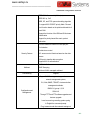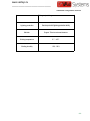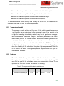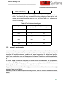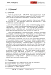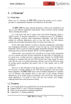
1
www.vaidsys.ru ______________________________ VAid823lt EPON OLT User Manual Hardware Configuration Manual 1. Product Introduction 2. Specification and Features 3. Installation Preparation 4. Installation 5. Setup and Configuration 6. Update Software 7. Troubleshooting 8. Optional interface module 9. Appendix RJ-45 Connector -1- www.vaidsys.ru ______________________________ Content Chapter1 Product Introduction.............................................................................- 3 1.1 VAid823lt EPON OLT Introduction........................................................ - 3 - 1.2 VAid823lt EPON OLT Typical Application............................................ - 3 - Chapter 2 Specifications and features............................................................ - 4 - 2.1 VAid823lt EPON OLT appearance........................................................- 4 - 2.2 VAid823lt EPON OLT Front Panel................................................... - 4 2.2.1 Front Panel............................................................................... - 5 - 2.2.2 EPON OLT SFP Port Feature................................................- 7 - VAid823lt EPON OLT Back Panel....................................................- 7 - 2.3 2.3.1 Back Panel............................................................................... - 7 - 2.3.2 Optional power.........................................................................- 8 - The VAid823lt EPON OLT Optional support dual AC power input, dual DC power input, AC + DC power input....................................................................- 8 2.4 VAid823lt EPON OLT System Features............................................- 8 - Chapter 3 Installation Preparation................................................................. - 13 - 3.1 Security Notice............................................................................................ - 13 3.2 Examine Installation Location................................................................... - 13 3.2.1 Temperature/Humidity.......................................................... - 14 - 3.2.2 Neatness.................................................................................- 14 - 3.2.3 Immunity requirements.........................................................- 15 - 3.3 Tools for Installation.................................................................................... - 16 - Chapter 4 Installation.......................................................................................... - 17 4.1 Installation Step......................................................................................- 17 4.1.1 Install to the Rack..................................................................- 17 - -1- www.vaidsys.ru ______________________________ 4.1.2 4.2 Connect to Ground................................................................................ - 18 4.2.1 AC power Installation............................................................- 19 - 4.2.2 DC power Installation........................................................... - 19 - 4.2.3 Connect to Ground................................................................- 19 - 4.3 Connect to Switch Console Port..........................................................- 20 4.3.1 Console Cable....................................................................... - 20 - 4.3.2 Connect to Console Port......................................................- 21 - 4.4 Check after the Installation...................................................................- 21 - Chapter 5 5.1 5.2 Install to the Platform............................................................- 18 - Booting and Configuration............................................................- 23 Local terminal configuration................................................................. - 23 - 5.1.1 Configuration environment.................................................. - 23 - 5.1.2 Connect configuration cable................................................- 23 - 5.1.3 Configure terminal parameter............................................. - 23 - Booting.....................................................................................................- 29 5.2.1 Examine before the power on............................................. - 29 - 5.2.2 Booting....................................................................................- 30 - Chapter 6 Software Upgrade............................................................................. - 31 Chapter 7 Trouble shooting................................................................................- 32 7.1 Power System Failure................................................................................ - 32 7.2 Configuration System Failure...............................................................- 32 7.2.1 Troubleshooting on No Displaying......................................- 32 - 7.2.2 Troubleshooting on displaying Illegible Characters............................- 33 8.1 RJ-45 Connector......................................................................................... - 34 8.2 Make the Cable........................................................................................... - 36 - -2- www.vaidsys.ru ______________________________ Hardware configuration manual Chapter1 Product Introduction 1.1 VAid823lt EPON OLT Introduction VAid811lt has two, three-speed forwarding capability, used primaril y for industrial electricity networks in the field of digital management, works for the National Grid distribution automation and electricity infor mation collection "to provide comprehensive, intelligent, strong, advanc ed, professional solution. Splitting ratio of up to 1:64, mixed networkin g support different types of ONU, operators' investments do minimized. 1.2 VAid823lt EPON OLT Typical Application The VAid823lt typical networking is as shown below: -3- www.vaidsys.ru ______________________________ Hardware configuration manual Chapter 2 Specifications and features 2.1 VAid823lt EPON OLT appearance Picture 2-1VAid823lt EPON OLT appearance -4- www.vaidsys.ru ______________________________ Hardware configuration manual 2.2 2.2.1 VAid823lt EPON OLT Front Panel Front Panel VAid823lt EPON OLT front panel are arranged as shown in the following diagram, the front panel contains 8 Gigabit Combo ports and 8 PON port, a number of LED in dicators, a console port and an AUX port: Picture 2-2 VAid823lt EPON OLT front panel The front panel LED indicator label are described in Table 2-1: Table 2-1 EPON OLT master card front panel indicator Indicator Panel Status Meaning Flash System operates normal Indicator Always SYS on or Always System operates abnormal off System status lights PWR1 Always System power supply is on normal. Always off PWR2 System power failure Always System power supply is on normal. Always off System power failure -5- www.vaidsys.ru ______________________________ Hardware configuration manual PWR AUX Port LEDs GE on System power supply is normal. off System power failure on Debug mode is turned on off Debug mode is turned off on Connection is normal. Flash Send or receive data off Port is not connected on REG off PON indicator on ACT off ONU registration on the PON port The PON port no ONU registration on The port ongoing data transceiver The port is not performing data transceiver -6- www.vaidsys.ru ______________________________ Hardware configuration manual 2.2.2 EPON OLT SFP Port Feature The VAid823lt OLT front panel 8 PON OLT SFP ports and eight Gigabit Combo ports. Table 2-2 EPON OLT SFP selected module description SFP module Center wavelength name Connector Fiber interface Maximum types of fiber specification transmission interface distance of optical fiber Receive 1310nm, SFP-EPON-LH10 SFP-EPON-LH20 send 1550nm Receive 1310nm, Single-mode fiber LC Single-mode send 1550nm fiber 10km 20km Table 2-6 GE SFP interface selected module description SFP module name Center Connector Fiber interface Maximum wavelength types of fiber specification transmission interface distance of optical fiber SFP-GE-SX-MM850 Multimode fiber 850nm 10km SFP-GE-SM1310-LH10 SFP-GE-SM1310-LH20 1310nm LC SFP-GE-SM1310-LH40 SFP-GE-SM1550-LH40 SFP-GE-SM1550-LH60 550m Single-mode fiber 1550nm 20km 40km 40km 60km Caution: The module types of GE SFP updates when the time changes, so if you need the accurate module type information, please require the marketing of New . 2.3 VAid823lt EPON OLT Back Panel 2.3.1 Back Panel -7- www.vaidsys.ru ______________________________ Hardware configuration manual The VAid823lt EPON OLT rear panel as shown below, comes standard with an AC 220V power supply interface. Supported by the device according to the user needs to modify the power supply module, configurable dual AC or dual DC power supp ly can also be modified for single DC power supply. Picture 2-3 EPON OLT back panel 1――2*power input options; 2――ground column; Caution: EPON OLT supports AC and DC, DC+AC or single DC or single AC. 2.3.2 Optional power The VAid823lt EPON OLT Optional support dual AC power input, dual DC power input, AC + DC power input. 2.4 VAid823lt EPON OLT System Features Table 2-4 Items EPON OLT system features VAid823lt Size(W×H×D) 1RU Cassette,442mm(L)×315mm(W)×44mm(H) Weigh <3kg Input voltage AC:90V~240V 47/63Hz -8- www.vaidsys.ru ______________________________ Hardware configuration manual DC:-36V ~ -72V Max power consumption Port < 32W 8 GE Combo ports 8 PON port Switching mode Store-and-forward (Store and forward) Switching capacity 32Gbps IEEE 802.3ah EPON IEEE802.3(10Base-T) IEEE802.3u(100Base-TX) IEEE802.3z(1000BASE-X) IEEE802.3ab(1000Base-T) IEEE802.1Q(VLAN) IEEEE802.1d(STP) Standard IEEEE802.1W(RSTP) IEEEE802.1S(MSTP) IEEE802.1p(COS) IEEE802.1x(Port Control) IEEE802.3x(flow- control) IEEE802.3ad(LACP) Each OLT interface hangs up to 64*ONU Each OLT transmission distance is up to 20Km VLAN,QinQ,Link aggregation,broadcast storm control Layer 2 feature Support up to 4096*VLAN; Support 16K MAC address table; Supports bandwidth control Aggregation group ACL/QOS 127 groups of up to eight members To support entrance, egress ACL Back pressure flow control (half duplex) -9- www.vaidsys.ru ______________________________ Hardware configuration manual IEEE 802.3x flow control (full-duplex) IEEE 802.1p, CoS WRR, SP, and FIFO queue scheduling algorithm To support 802.1P/DSCP priority Mark / Remark Limit function based on the uplink and downlink of each ONU Support the function of the DBA and SLA stream classification Support for priority-based flow mark, packet redirection Limit the maximum number of users per port Port Isolation Packet storm control Security Feature ACL access control functions based on the data stream PON port to transfer data encryption Support 802.1X authentication IGMP v1/v2/v3 Multicast IGMP Snooping Multicast VLAN, managed multicast Port Mirroring Support Support SNMP management support for network management system; CLI, Web, SNMP, TELNET, cluster and other management methods. Configuration and Management RMON V1, group 1,2,3,9 SSHv1/v2 Through TFTP and FTP software upgrades and bootrom upgrade Local or server log recording system syslog In English the command prompt Ping, traceroute and other network testing tool - 10 - www.vaidsys.ru ______________________________ Hardware configuration manual Debug output debug Lightning protection Service port with lightning protection ability Maintain Support Telnet remote maintenance Working temperature 0℃~45℃ Working humidity 10%~90% - 11 - www.vaidsys.ru ______________________________ www.vaidsys.ru ______________________________ Hardware configuration manual Chapter 3 Installation Preparation 3.1 Security Notice To avoid device damaging and bodily injured caused by unsuitable operation, please follow these notices: Before cleaning switch, pull out the plug of switch. Do not wipe it with wet cloth and liquid. Do not locate switch near water or humid place, and prevent water and humidity entering switch. Do not locate switch on unstable case or desk. Falling may cause severe damage to switch. Keep the ventilation of the room and the switch. Switch can work normally under correct power pressure. Please affirm the power pressure of switch is the same as that marked. To avoid the danger of electricity attacking, do not open the cabinet shell though the switch is power off. 3.2 Examine Installation Location VAid823lt EPON OLT must use indoor, no matter install in the cabinet or put the pla tform directly, it should ensure below conditions : - 13 - www.vaidsys.ru ______________________________ Hardware configuration manual Make sure there is space between the wind inlet and vents to hot dissipation. Make sure the cabinet or platform has the good vents dissipation system. Make sure the cabinet or platform is firmed to bear the device weight. Make sure the cabinet or platform is connected to the ground. To ensure the device works normally and prolong the service life, the installation en vironment also need to fulfill the below requirements. 3.2.1 Temperature/Humidity To guarantee normal working and life span of the switch, certain temperature and humidity can be maintained in the equipment room. If the humidity is to o high, the insulating of insulating material may be not good, even creepage and sometimes may cause the change of mechanical performance and rustin ess of metal parts. If the related humidity is low, the insulated gasket will be shrinkable which will cause the looseness of captive screw. In the dry climat e, electrostatics may be caused which is harmful for the CMOS circuit of swit ch. The higher the temperature is, the more dangerous it is. It will greatly re duce the reliability of the switch, and long-term high temperature will affect th e life span of the switch. Over-high temperature may accelerate the aging of the insulated materials. 3.2.2 Neatness Dust is harmful for the operation of the switch. The dust in the room fell on the equipment may cause the absorption of the electrostatics, which may influ ence the life span of the switch and cause the communication failure. The re quirement for the dust and the grin size is as following. Table 3-1 The requirement for the dust in switching room The maximum diameter (um) 0.5 1 3 5 The maximum thickness (the 1.4×10⁷ 7×10⁵ 2.4×10⁵ 1.3×10⁵ - 14 - www.vaidsys.ru ______________________________ Hardware configuration manual number of grain per m3) Besides dust, switching room also strictly requires the content of salt, acid and sulfide. This harmful gas may accelerate the rusting and aging of same parts. Such harmful gas must be prevented as SO2, H2O, NO2, NH3 and CL2. The restricted value is as following: Table 3-2 The limitation of harmful gas 3.2.3 Gas Average (mg/m3) Maximum (mg/m3) SO2 0.2 1.5 H2S 0 0.03 NO2 0.04 0.15 NH3 0.05 0.15 Cl2 0 0.3 Immunity requirements In the use of equipment may be derived from the system external interference, such interference by capacitive, inductive coupling, electromagnetic radiation, public impedance (including the grounding system ) coupling and wires ( power line, the signal lines and the output lines ) conduction mode on the equipment influence. Therefore we should pay attention to: AC power supply system for TN system, AC power source socket should be equipped with protective earth ( PE ) of single phase three wire power supply socket, so that the device can effectively filter the filter circuit interference of electric network. Equipment location away from the high power radio transmitter, radar transmitter, high frequency large current device. Necessary to take the electromagnetic shielding method, such as interface cable with shielded cables. - 15 - www.vaidsys.ru ______________________________ Hardware configuration manual 3.3 Tools for Installation Tools needed: Cross screwdriver Antistatic wrist strap Wire stripper Cable needed: Power cable Console cable RJ-45 connector reticle Device needed: Configuration terminal Caution (can be PC) EPON OLT doesn’t provide installation tools which are prepared by user .. - 16 - www.vaidsys.ru ______________________________ Hardware configuration manual Chapter 4 Installation Caution: There is an anti-dismantle seal remarked New on the installation screw outside the case. When the agents maintain the device, it is required that seal is entire. So before user opens the device, please get the permit from local agent, or user will take the responsibility with unauthorized operation maintenance. 4.1 Installation Step 4.1.1 Install to the Rack VAid823lt EPON OLT can install on the rack, the process is as below: Step 1: Examine grounding and stability of the cabinet. Use screw to fasten hanger to the two sides of the front board and back board of the switch; Step 2: Locate switch on the salver of the cabinet. Move it to the suitable location along with the slide of the switch. Keep some space between switch and the slide. Step 3: Fasten hanger to the fixed slide of the cabinet to guarantee the bracket of eac h slot and hanger of the switch are fastened to the cabinet. - 17 - www.vaidsys.ru ______________________________ Hardware configuration manual Figure 4-1 EPON OLT installation Caution: The fixed angle iron is only for fixation not for load-bearing. The device install on the cabinet, slide (fix on the cabinet)under the device is to bear the weight. 4.1.2 Install to the Platform At more situations, users always put the device to the clear platform. The operation is simple, please be noted of below steps: Make sure the platform is stable and good connected to the ground Leave 10cm space for the heat dissipation around the device Don’t put the heavy things to the device. 4.2 Connect to Ground VAid823lt EPON OLT adopts hot swappable power box. It also supports AC and D C power backup for each other mixed-mode. There are two kinds of power box, AC and DC, the range of power is AC 100V~ 240V - 18 - www.vaidsys.ru ______________________________ Hardware configuration manual DC –36V~–72V 4.2.1 AC power Installation 1. The input range of AC 100V~240V,50/60Hz AC 2. Connect to the AC power cord The device randomly with the power line is inserted into the enclosure on the rea r panel of the power socket, another end is inserted to provide AC power outlet. 4.2.2 DC power Installation 1. The input range of DC -36V~-72V, DC 2. Connect to the DC power cord Plug the DC power cord into outlet on the rear panel, the other end red wire inserts into the DC power positive electrode, black wire inse rts to the DC power negative electrode. 4.2.3 Connect to Ground Caution: The device well-connected can protect switch from lightning and jamming, user must correctly connect the ground carefully. VAid823lt EPON OLT power supply input end connected with noise filter, which is directly connected with the chassis protection, so it must be well grounded, so that the induction electric, electric leakage can be safely into earth, and improving the electromagnetic interference resistance ability. The device attached to the chassis ground end randomly received equipment panel after grounding pole, the other end of the nearest good grounding. Requirements for grounding resistance less than 4 ohm. If the device is mounted on the standard 19 " cabinet, it also requires 19 inch standard cabinet earthing. - 19 - www.vaidsys.ru ______________________________ Hardware configuration manual 4.3 Connect to Switch Console Port 4.3.1 Console Cable Console cable is a shield cable of 8 cores. One end is crimped RJ-45 connector, whi ch is inserted to Console interface; the other end is a connector with DB-9 (holes). T he Console cable is as the following picture: A Direction B Direction magnify magnify Picture 4-2 Console cable Table 4-1 Console cable connection RJ45 Signal Direction DB-9 1 CTS → 8 2 DSR → 6 3 RXD → 2 4 GND - 5 5 GND - 5 6 TXD ← 3 7 DTR ← 4 8 RTS ← 7 - 20 - www.vaidsys.ru ______________________________ Hardware configuration manual 4.3.2 Connect to Console Port After configuring the device, the steps of cable connection as below: Step 1: Put DB-9 to the configured host or console ; Step 2: Connect RJ-45 to console Caution: Please recognize the interface identification to avoid inserting the other interfaces by mistake. 4.4 Check after the Installation Check the selected power is the same as identification power or not. Check the ground wire is connected or not Check the console , power input cable are connected or not. - 21 - www.vaidsys.ru ______________________________ www.vaidsys.ru ______________________________ Hardware configuration manual Chapter 5 Booting and Configuration Caution: EPON OLT can provide two ways of configuration for users: First: Local terminal configuration. Terminal (can be PC) connects to the Console by serial interface; Second: Terminal Telnet configuration. Configuration terminal connects to device by IP network. Pay attention to configure IP address, net mask before using Telnet terminal. 5.1 Local terminal configuration 5.1.1 Configuration environment Use configuration interface cable connect Console interface to terminal (such as P C). 5.1.2 Connect configuration cable Step 1: Connect DB-9 connector to PC or serial interface of terminal. Step 2: Connect RJ-45 to Console of the switch. 5.1.3 Configure terminal parameter Step 1: Boot PC and run terminal emulation program (such as hyperterminal in Win dows). Step 2: Configure terminal parameter (take the configuration of parameter ofhyperter minal in Windows 2000 as an example). Parameters are: baud rate is “9600”, data bit is “8”, and parity check is “none”, stop bit is “1”, flow control is “none”, and cho ose terminal emulation as “auto-detect”. The configuration is as following: - 23 - www.vaidsys.ru ______________________________ Hardware configuration manual Click “start”-“program”-“accessory”-“communication”-“hyperterminal” to set up new con nection. System will display interface as following. Input the name of the new conne ction in “name”, such as EPON. Picture 5-1 Explanation of hyperterminal connecting interface Click [yes] to the interface [connecting to] as following. Choose serial interface used by connect ion in “use in connection”. - 24 - www.vaidsys.ru ______________________________ Hardware configuration manual Picture 5-2 Configuration of using serial interface in hyperterminal After choosing serial interface, click [yes] to display corresponded serial attribution interface as followi ng. Configure baud rate to be “9600”, data bit to be “8”, parity check is “none”, stop bit is “1”, flow control is “none”. - 25 - www.vaidsys.ru ______________________________ Hardware configuration manual Picture 5-3 Serial parameter configuration Click [configure] in hyperterminal attribution to configure serial interface attribute as following: - 26 - www.vaidsys.ru ______________________________ Hardware configuration manual Picture 5-4 configure serial interface attribute in hyperterminal attribution interface After configuring serial parameter, click [yes] to enter hyperterminal interface as following: - 27 - www.vaidsys.ru ______________________________ Hardware configuration manual Picture 5-5 hyperterminal window Choose (attribution) in typerterminal window to enter attribution window. Click [configure] to enter attribution configuration window (as in following picture). Choose terminal emulation as “auto -detect”, then click [yes]. - 28 - www.vaidsys.ru ______________________________ Hardware configuration manual Picture 5-6 Configuration of terminal emulation in attribution configuration 5.2 Booting 5.2.1 Examine before the power on Examine as following before the power of VAid823ltEPON OLT is on: The correct connection of power wire The consistency of the power supply and the power that switch needed The correct connection of configuration cable. The terminal or PC for configuration has been configured. - 29 - www.vaidsys.ru ______________________________ Hardware configuration manual 5.2.2 Booting After the power is on, followings will be displayed: Username(1-32 chars): Input username and press enter button. The prompt of inputting password is as foll owing: Password(1-16 chars): After inputting password, followings are displayed: Optiway> At this time, user can check and configure system information of device. - 30 - www.vaidsys.ru ______________________________ Hardware configuration manual Chapter 6 Software Upgrade General software upgrading uses serial interface which is very slow, cost long time and inconvenient. VAid823lt EPON OLT introduces xmodem, tftp and ftp to realize the conv enience of software upgrading and file downloading. EPON OLT can upgrade application program on line, load configuration file by xmodem, tftp and ftp, and also u pload configuration files by xmodem, tftp and ftp. 1. Upload configuration file through TFTP(refer to software configuration manual) 2. Download configuration file through TFTP(refer to software configuration manual) 3. Download application file through TFTP(refer to software configuration manual) Download application file through TFTP. The command is: load application tftp tftp-server filename Download application file through TFTP: Step 1: Enable TFTP server and configure download destination path; Step 2: Imput TFTP download command. Example: Download application program app.arj from IP address 192.168.0.100. Enabl e TFTP server and configure download destination path. Configure it in privileged mod e: Optiway#load application tftp 192.168.0.100 app.arj There will be displaying as following if succeed: Application file has been downloaded via tftp successfully. The new application will not be effective until the device is rebooted. Caution:The new application will not be effective until the device is rebooted. ©2011 All Rights Reserved - 31 - www.vaidsys.ru ______________________________ Hardware configuration manual Chapter 7 Troubleshooting 7.1 Power System Failure VAid823lt EPON OLT can check the power system failure according to the power indicator on the front board: when the power system works normally, the power indicator keeps on; if it is off, please examine as following: The correct connection of power wire. The matching of power supply of switch and power required. If the power switch open 7.2 Configuration System Failure After The power of VAid823lt EPON OLT is on, if the system works normally, the booti ng information will be displayed in configuration terminal; if there is failure in configurati on system, it will display nothing or illegible characters. 7.2.1 Troubleshooting on No Displaying After the power is on and if the configuration terminal displays nothing, please examine the device as following: The power works normally. The correct connection of Console cable - 32 - www.vaidsys.ru ______________________________ Hardware configuration manual If there is no problem in above examination, maybe there is something wrong with the parameter configuration of the terminal (such as hyper terminal) or the configuration cab le. 7.2.2 Troubleshooting on displaying Illegible Characters If illegible characters are displayed, parameter configuration of terminal (such as hyper terminal) is incorrect. Please affirm parameter configuration of terminal (such as hyper terminal): baud rate is “9600”, data bit is “8”, and parity check is “none”, stop bit is “1”, flow control is “none”, and choose terminal emulation as “auto-detect”. - 33 - www.vaidsys.ru ______________________________ Hardware configuration manual Chapter 8 Appendix RJ-45 Connector 8.1 RJ-45 Connector 1000Base-TX interface and debug network interface of VAid823lt EPON OLT uses RJ45 connector. Picture 9-1 describes the plug of standard RJ-45, connector and function of each pin of RJ-45 in each mode Picture 9-2, 9-3 describe the connecting of parallel reticle and crossing reticle. Table 9-1 describes the function of each pin of RJ-45 in MDI mode; Table 9-2 describes the function of each pin of RJ-45 in MDI mode. Picture 8-1 Standard RJ-45 plug and connector Picture 8-2 Parallel reticle - 34 - www.vaidsys.ru ______________________________ Hardware configuration manual Picture 8-3 Crossing reticle Table 8-1 Pin distribution of RJ-45 MDI interface 10/100Base-T Pin number Signal Function 1000Base-T Signal Function 1 Tx+ Sending data BIDA+ A to the data 2 Tx- Sending data BIDA- A to the data 3 Rx+ Receiving data BIDB+ B to the data 4 Reserved - BIDB- B to the data 5 Reserved - BIDC+ C to the data 6 Rx- BIDC- C to the data 7 Reserved - BIDD+ D to the data 8 Reserved - BIDD- D to the data Receiving data Table 8-2 Pin distribution of RJ-45 MDIX interface 10/100Base-T Pin number Signal Function 1000Base-T Signal Function 1 Rx+ Receiving data BIDB+ B to the data 2 Rx- Receiving data BIDB- B to the data 3 Tx+ Sending data BIDA+ A to the data 4 Reserved - BIDC+ C to the data 5 Reserved - BIDC- C to the data 6 Tx- Sending data BIDA- A to the data 7 Reserved - BIDD+ D to the data - 35 - www.vaidsys.ru ______________________________ Hardware configuration manual 8 Reserved - BIDD- D to the data 8.2 Make the Cable Appendix picture 2 is the example of making Ethernet cable of RJ-45 connector by usi ng categories 5 twisted-pair. Picture 8-4 The picture of categories 5 twisted-pair Categories 5 twisted-pair consists of 8-core filament with the color on the insulated laye r being grouping sign. Usually, it uses a single color and single color with white to be a pair of standard, and sometimes uses color points to be a pair of sign. Here, take th e former as an example. Categories 5 twisted-pair consists of 8-core filament with the color on the insulated laye r being grouping sign. Usually, it uses a single color and single color with white to be a pair of standard, and sometimes uses color points to be a pair of sign. Here, take th e former as an example. - 36 - www.vaidsys.ru ______________________________ Hardware configuration manual SIDE1 1 234 5678 1 23 45678 SIDE 1 1=white/orange 2=orange 3=white/green 4=blue 5=white/blue 6=green 7=white/brown 8= brown SIDE 2 1=white/orange 2=orange 3=white/green 4=blue 5=white/blue 6=green 7=white/brown 8=brown SIDE2 Picture 8-5 Make parallel reticle SIDE1 1234 56 78 1234 5678 SIDE1 1=white/orange 2=orange 3=white/green 4=blue 5=white/blue 6=green 7=white/brown 8= brown SIDE2 1=white/green 2=green 3=white/orange 4=blue 5=white/blue 6=orange 7=white/brown 8=brown SIDE2 Picture 8-5 Make crossing reticle - 37 -