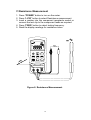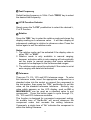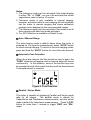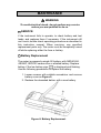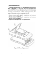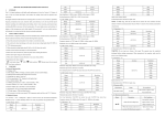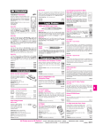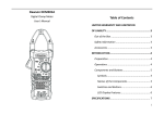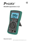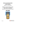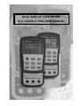
1
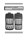
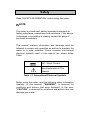
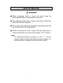
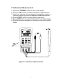
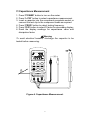
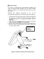
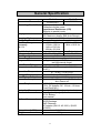
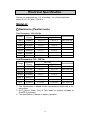
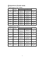
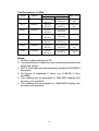
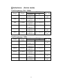
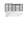
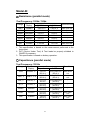
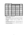
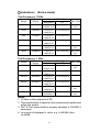
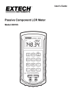
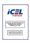
DUAL DISPLAY L/C/R METER
ELC-132A/ELC-133A USER MANUAL
ATTENTION
In this instruction manual,
The ELC-133A is represented with Model-A.
The ELC-132A is represented with Model-B.
Model-A
ELC-133A
Model-B
ELC-132A
L/C/R/D/Q
Items
Parameters Measured
L/C/R/D/Q/Θ
Measuring Circuit Mode Inductance (L)
–Defaults to series mode
Capacitance/ Resistance (C/R)
-Defaults to parallel mode
L/C/R: Maximum display 19999
Displays
D/Q: Maximum display 999 (Auto Range).
Auto & Manual
Ranging Mode
3 terminals with sockets
Measuring Terminals
120Hz= 120 Hz
100Hz=100 Hz
Test Frequency
1KHz =1010 Hz
120Hz= 120 Hz
Accuracy:
1KHz =1010 Hz
±0.1 %
10KHz= 9.6 KHz
Included
Excluded
Backlit display
1%, 5%, 10%, 20%
1%, 5%, 10%
Tolerance mode
0.6Vrms approx.
Test Signal Level
1 time/second, nominal
Measuring Rate
Approx. 1 second/ DUT (device under
Response time
test)(@ manual range)
5 minutes approx. without operation
Auto Power-Off
Temperature Coefficient 0.15 x (Specified Accuracy) / ℃(0-18℃ or
28-40℃)
Operation Temperature
0℃ to 40℃; 0-70% R.H.
Storage Temperature
-20℃ to +50℃; 0-80% R.H.
Approx. 6.8V
Low Battery Indication
0.1A/250V Fuse (input protective)
Protective Fuse
Test alligator clips (pair)
Standard Accessories
DC 9V Battery.
User manual
Carrying case
Optional Accessories
RS232 package
SMD Tweezers
DC Adaptor (EA112: AC120V) / (EA55:
AC220V).
184/ 87/ 41 mm
Dimensions (L/W/H)
330 grams
Weight
DUAL DISPLAY L/C/R METER
INSTRUCTION MANUAL
Model-A
Model-B
Table of Contents
PAGE
1
Safety
Introduction
3
Front Panel Illustration
4
LCD Display Illustration
5
How to Operate
7
Operating Instructions
11
11
11
11
12
12
12
12
13
13
13
14
15
15
15
16
Data Hold
Static Recording
Dissipation Factor / Quality Factor/ Phase Angle
Test Frequency
L/C/R function selector
Relative
Tolerance
Auto/manual ranging
Automatic Fuse Detection
Parallel / Series Mode
Calibration
Auto Power Off/ Disable Auto Power Off
Low Battery Indication
Backlit Display
Communication
General Specification
17
Electrical Specification
18
Maintenance
26
i
Safety
Read "SAFETY INFORMATION" before using this meter.
NOTE
The meter is a hand-held, battery-operated instrument for
testing inductance, capacitance and resistance. If this device
is damaged or something is missing, contact the place of
purchase immediately.
This manual contains information and warnings must be
followed to ensure safe operation as well as to maintain the
meter in a safe condition. Some common international
electrical symbols used in this manual are shown below
Table:
DC - Direct Current
See Explanation In The
Manual
Table 1-1. International Electrical Symbols
Before using the meter, read the following safety information
carefully. In this manual, "WARNING", is reserved for
conditions and actions that pose hazard(s) to the user;
"CAUTION", is reserved for conditions and actions that may
damage your meter.
1
SAFETY INFORMATION
To ensure that you use this device safely, follow the
safety guidelines listed below:
This meter is for indoor use, altitude up to 2,000 m.
The warnings and precautions should be read and well
understood before the instrument is used.
Use this device only as specified in this manual;
otherwise, the protection provided by the meter may be
impaired.
When measuring in-circuit components, first de-energize
the circuits before connecting to the test leads.
Discharge capacitor before testing.
The meter is safety-certified in compliance with EN61010
(IEC 1010-1) Installation Category II (CAT. II) 50 V,
Pollution Degree 2 environment.
Use the meter only as specified in this manual. Otherwise,
the protection provided by the meter may be impaired.
The power for the meter is supplied with a single
standard 9V battery. But also a line operation is possible
using a 12V AC to DC adaptor. If a power adaptor is
selected, please be sure to use fulfilled the safety
requirements of a relevant IEC standard.
2
Introduction
This 19,999-count L/C/R hand-held meter is a special
microprocessor-controlled meter for measuring functions of
inductance, capacitance and resistance. Extremely simple
to operate, the instrument not only takes absolute parallel
mode measurements, but also capable of series mode
measurement. The meter provides direct and accurate
measurements of inductors, capacitors and resistors with
different testing frequencies. It is selectable for auto and
manual ranging.
Front panel pushbuttons maximize the convenience of
function and feature selection such as data hold; maximum,
minimum and average record mode; relative mode; tolerance
sorting mode; frequency and L/C/R selection.
The test data can be transferred to PC through an optional full
isolated optical RS232C interface.
Backlight display for easy reading in dark places (Model-A
only).
A tilt stand provides position flexibility for viewing and
operating the meter. The over-molding rubber case protects
the meter to be stronger. With single 9V battery operation is
standard for the meter, a DC 12V power adaptor can also be
used as an optional power input.
3
Front Panel Illustration
1.
2.
3.
4.
LCD display
Power ON/OFF button
RS232 and Backlit button
Dissipation factor, Quality factor and Phase angle
selection button
5. Test frequency selection button
6. Inductance, Capacitance and Resistance function
selection button. Parallel and series mode selection
button
7. Tolerance mode selection button
8. Data hold, Maximum, Minimum and Average reading
selection button
9. Range selection button
10. Relative mode and Calibration selection button
11. DC 12V adaptor input
12. Input sockets and Terminals
1
2
3
RS232
4
5
6
7
u
u
u
u
RS232
RS232
HOLD
REC
8
9
AUTO
TOL
RS232
REL
CAL
10
HOLD
REC
AUTO
TOL
REL
CAL
11
12
Figure-1. Front panel for Model-A and Model-B.
4
LCD Display Illustration
3 4 6 10
2
5 7 8 9
11
1
16
17
18
19
u
u
20
RS232
12
13
14
15
21
22
23
24
25
26
Figure 2. LCD Display.
1.
2.
3.
4.
5.
6.
7.
AUTO: Auto-ranging indicator
LCR: L, C or R function indicator
MAX: Maximum reading indicator
AVG: Average reading indicator
REL: Relative mode indicator
MIN: Minimum reading indicator
DH: Data hold indicator
Θ: Phase angle indicator (Model-A only )
8.
9. Q: Quality factor indicator
10. D: Dissipation factor indicator
11.
12.
13.
14.
15.
16.
17.
18.
: Secondary display
: Beeper tone indicator for tolerance mode
%: Tolerance (percentage) indicator
deg: Phase Angle degree indicator (Model-A only )
kHz: Frequency indicator
MAX AVG MIN: Recording mode indicators
TOL: Tolerance mode indicator
1%5%10%20%: Tolerance sorting (percent) indicator
5
19.
: Auto power- off indicator
20.
: Low battery indicator
21. PAL: Parallel mode indicator
22. SER: Series mode indicator
23. MkΩ: Resistance (Ohm) indicator
24.
: Inductance (Henry) indicator
25.
26.
: Capacitance (Farad) indicator
: RS232 indicator
Special Indication Characters
: Indicates short connectors
: Indicates open connectors
: Indicates calibration mode
: Indicates damaged or open fuse
6
How To Operate
Caution
◆ When measuring within a circuit, the circuit must be
de-energized before connecting the test leads.
◆ The instrument that used in dusty environment should be
wiped and cleaned regularly.
◆ Do not leave the instrument exposed to direct heat from the
sun or beat source for long periods.
◆ Before removing the cover, ensure that the instrument is
disconnected from any circuit and in power "OFF" position.
Note:
For achieving optimum precision for all L, C and R
measurements at either the highest or lowest ranges, it is
recommended to calibrate the meter before testing.
7
Inductance Measurement
1. Press the "POWER" button to turn on the meter.
2. Press “L/C/R” button to select inductance measurement.
3. Insert an inductor into component receptacle socket or
connect the test clip to the component leads as required.
4. Press “FREQ” button to select testing frequency.
5. Press “D/Q” button to select Q factor for secondary display.
6. Read the display readings for inductance value and quality
factor.
u
RS232
HOLD
REC
AUTO
TOL
REL
CAL
Figure-3. Inductance Measurement.
8
Capacitance Measurement
1. Press "POWER" button to turn on the meter.
2. Press “L/C/R” button to select capacitance measurement.
3. Insert a capacitor into the component receptacle socket or
connect the test clip to the component leads as required.
4. Press “FREQ” button to select testing frequency.
5. Press “D/Q” button to select D factor for secondary display.
6. Read the display readings for capacitance value and
dissipation factor.
Warning
To avoid electrical hazards, discharge the capacitor to be
tested before measuring.
RS232
HOLD
REC
AUTO
TOL
REL
CAL
Figure-4. Capacitance Measurement.
9
Resistance Measurement
1. Press "POWER" button to turn on the meter.
2. Press “L/C/R” button to select Resistance measurement.
3. Insert a resistor into the component receptacle socket or
connect the test clip to the component leads as required.
4. Press “FREQ” button to select testing frequency.
5. Read the display readings for resistance value.
RS232
HOLD
REC
AUTO
TOL
REL
CAL
Figure-5. Resistance Measurement.
10
Operating Instructions
Data Hold
This data hold function allows the operator to freeze the
display. To enter this mode, press the "HOLD" pushbutton;
press again to release.
Static Recording™
Press the "REC" pushbutton for more than one second to
enter the static recording mode. The maximum and
minimum readings are then stored in memory, while a
beeping tone is produced when a new tested value has been
recorded. Push the same button to cycle through the
maximum, minimum and average of the present readings.
The MAX, MIN or AVG indicators will display on LCD will turn
on to indicate what value is being displayed. Whenever the
"MAX AVG MIN" indicators appear on the LCD
simultaneously, the display reading is always a present value.
To exit this mode, press and hold the pushbutton for more
than one second.
Notes:
1. Static recording captures only stable values and updates
the memory; it will not record any "OL" (overload) value for
any of the L/C/R functions. In addition, the meter will not
record which values are below 50 counts in Capacitance
measurement.
2. Static recording is only available in manual ranging;
however, activation while in auto-ranging will automatically
set meter to manual ranging and cause calibration prompts
to be displayed in the recommended ranges.
Dissipation Factor / Quality Factor/ Phase Angle
The "D/Q/ Θ " value can be displayed interchangeably
pressing the "D/Q/ Θ " button when the meter is set
Inductance or Capacitance mode. It does not apply
resistance measurement. The phase angle is available
Model-A only.
11
by
to
to
on
Test Frequency
Default testing frequency is 1KHz. Push "FREQ" key to select
the desired test frequency.
L/C/R Function Selector
Simply press the "L/C/R" pushbutton to select the desired L,
C or R function.
Relative
Press the "REL" key to enter the relative mode and stores the
display reading as a reference value. It will then display all
subsequent readings in relative to reference value. Press the
button again to exit the relative mode.
Notes:
1. The relative mode can’t be activated if the display value is
either "OL" or "0000".
2. Relative mode is only available in manual ranging;
however, activation while in auto-ranging will automatically
set the meter to manual ranging and cause calibration
prompts to be displayed in the recommended ranges.
3. The relative mode cannot be activated if the meter is set at
auto-ranging with data hold activated.
Tolerance
There are 1%, 5%, 10% and 20% tolerance range. To enter
this tolerance mode, insert the appropriate component as a
standard value into the socket or connect the component to
the test probes, then press the "TOL" pushbutton to set this
value, as the standard reference tolerance. Similarly, any
value which appears on the LCD display, such as DH or
MAX/MIN/AVG, can be used as a standard value to sort
components. Press this button again to cycle through 1%,
5%, 10% and 20% tolerance as desire.
This function is designed for convenient component sorting.
An audible tone of “Be-Be-Be” will sound whenever the
component under test exceeds the setting tolerance.
Conversely, a single tone of “Be” indicates the component is
within the setting tolerance.
12
Notes:
1. The tolerance mode can’t be activated if the tested display
is either "OL" or "0000"; nor can it be activated the tested
capacitance value is below 10 counts.
2. Tolerance mode is only available in manual ranging;
however, activation while in auto-ranging will automatically
set the meter to manual ranging and cause calibration
prompts to be displayed in the recommended ranges.
3. The tolerance mode can’t be activated if the meter is set at
auto-ranging with data hold mode activated.
4. For 20% selection is available on Model-A only.
Auto / Manual Range
The auto-ranging mode is default status when the meter is
powered on. For specific measurement, press "AUTO" button
to select manual ranging. To return to the auto-ranging mode,
press and hold the "AUTO" button for more than one second.
Automatic Fuse Detection
When the meter detects that the protective fuse is open, the
"FUSE" character will appear and an internal beep will sound
continuously. In this situation, none of the function keys can
be operated and all other meter functions will be discontinued.
Fuse replacement is required.
Figure-6. Fuse Detection
Parallel / Series Mode
The meter is capable of displaying Parallel and Series mode
data for all ranges. The parallel mode is default for
Capacitance and Resistance measurements, and the series
mode is default for Inductance measurement. Press "L/C/R"
button for more than 1 second to toggle "SER" and "PAL"
mode.
13
Calibration
Calibration is available to all ranges. Simply press and hold
"CAL" button for more than one second to enter the
calibration mode and calibration prompts will be displayed.
Follow the prompts for open connector (
) or short
connector (
) connection and press the "CAL" button.
After calibration is completed, the meter will be restored to
normal display and ready for normal usage.
Figure-7. Open/ Short Calibration
The function calibrates the meter’s internal parameters as
well as external connector residues for further measuring. It
is highly recommended to calibrate extremely high or low
ranges for L, C and R before making precision measurements.
Calibration prompts will be displayed automatically every time
those ranges are manually or functionally selected, (e.g. REL,
TOL, REC etc.), and calibration is recommended. Simply
follow the open connector (
) or short connector (
)
instruction and then press the "CAL" button. You may skip
the calibration by pressing the "D/Q" button.
Notes:
1. Changing measurement frequencies is handled the same
as selecting a different hardware range, and so automatic
calibration prompts will be displayed in the recommended
ranges.
2. Be sure to use same testing position after short calibration.
14
Auto Power Off/ Disable Auto Power Off
When the meter has not been used for five minutes after the
last operation was made, a long "beep" tone will sound. The
meter will then automatically enter a "sleep" mode and there
will be no display on the LCD. To reactivate the meter, simply
press any pushbutton. After re-activating.
When the meter is to be used for long period, the auto
power-off can be disabled by pressing and holding "L/C/R"
button while turning meter ON. Release the button, and press
any button again. The
symbol will be disappeared to
confirm that the auto power off has been disabled.
By using a 12V AC adaptor as an optional power source, auto
power off is disabled automatically.
Note: It is recommended that the meter should always be
switched off when not in use.
Low Battery Indication
" symbol flashes on the display, the battery
When the "
voltage is below normal working voltage and is weakening.
Replace battery with a new one to maintain accuracy of the meter.
Backlit Display (Model-A only)
Press and hold "
backlit ON/OFF.
" key for more than one second to toggle
15
Communication
The meter is reserved with communication capability. By
using an optional RS232 package, with full optical isolated
cable and software. This function will assist user to record
data easily.
Referring the following procedures to set up the
communication between your meter and personal computer.
1. Fixes one side of cable to the meter, and the text side shall
be facing up. To connect the 9-pin’s terminal of cable to
communication port 1 or 2 of personal computer. See the
Figure-8.
2. Press "RS232" button to enable this interface. You will find
that the symbol of “
” is lit on the display.
3. Execute the software to take the data for your applications.
4. Be sure to push the snap ends on the cable of meter side
for removing the cable.
The text side
shall be
facing up.
Figure-8. Cable Connection Of Communication
16
General Specification
Items
Model-A
Model-B
L/C/R/D/Q
Parameters Measured
L/C/R/D/Q/Θ
Measuring Circuit Mode Inductance (L)
–Defaults to series mode
Capacitance/ Resistance (C/R)
-Defaults to parallel mode
L/C/R: Maximum display 19999
Displays
D/Q: Maximum display 999 (Auto Range).
Auto & Manual
Ranging Mode
3 terminals with sockets
Measuring Terminals
120Hz= 120 Hz
100Hz=100 Hz
Test Frequency
1KHz =1010 Hz
120Hz= 120 Hz
Accuracy:
1KHz
=1010
Hz
±0.1 %
10KHz= 9.6 KHz
Included
Excluded
Backlit display
1%, 5%, 10%, 20%
1%, 5%, 10%
Tolerance mode
0.6Vrms
approx.
Test Signal Level
1 time/second, nominal
Measuring Rate
Approx. 1 second/ DUT (device under
Response time
test)(@ manual range)
5 minutes approx. without operation
Auto Power-Off
Temperature Coefficient 0.15 x (Specified Accuracy) / ℃(0-18℃ or
28-40℃)
Operation Temperature
0℃ to 40℃; 0-70% R.H.
Storage Temperature
-20℃ to +50℃; 0-80% R.H.
Approx. 6.8V
Low Battery Indication
Approx. 40mA for operation/ 0.08mA after
Power Consumption
Auto Power-off.
1) DC 9V Battery
Power Requirements
2) Ext. DC Adaptor: DC 12Vmin –15Vmax.
(Load 50mA Min.)
0.1A/250V Fuse (input protective)
Protective Fuse
Test alligator clips (pair)
Standard Accessories
DC 9V Battery.
User manual
Carrying case
Optional Accessories
RS232 package
SMD Tweezers
DC Adaptor (EA112: AC120V) / (EA55:
AC220V).
184/ 87/ 41 mm
Dimensions (L/W/H)
330 grams
Weight
17
Electrical Specification
Accuracy is expressed as: ± (% of reading + no. of least significant
digits) at 23℃±5℃and <75% R.H.
Model-A:
Resistance (Parallel mode)
Test Frequency: 100 / 120 Hz
Accuracy
Maximum
Range
Display
@100 Hz
@120Hz
10MΩ
9.999MΩ
2.0%+8 *3
2000KΩ
1999.9KΩ
200KΩ
Specified Note
2.0%+8 *3
After open cal.
0.5%+5
0.5%+5
After open cal.
199.99KΩ
0.5%+3
0.5%+3
-
20KΩ
19.999KΩ
0.5%+3
0.5%+3
-
2000Ω
1999.9Ω
0.5%+3
0.5%+3
-
200Ω
199.99Ω
0.8%+5
0.8%+5
After short cal.
20Ω
19.999Ω
1.2%+40
1.2%+40
After short cal.
Test Frequency: 1K / 10K Hz
Range
Maximum
Display
Accuracy
@1K Hz
@10KHz
10 MΩ
9.999MΩ
2.0%+8 * 3
3.5%+10 * 3
After open cal.
2000 KΩ
1999.9KΩ
0.5%+5
2.0%+10
After open cal.
200 KΩ
199.99KΩ
0.5%+3
1.5%+5
-
20 KΩ
19.999KΩ
0.5%+3
1.5%+5
-
2000 Ω
1999.9 Ω
0.5%+3
1.5%+5
-
200 Ω
199.99 Ω
0.8%+5
2.0%+10
After short cal.
20 Ω
19.999 Ω
1.2%+40
2.5%+200
After short cal.
Specified Note
Notes:
1. This specification is based on the measurement performed at the
test socket.
2. DUT (Device Under Test) & Test leads be properly shielded to
GUARD if necessary.
3. This specification is based on battery operation.
18
Capacitance (Parallel mode)
Test Frequency: 100 / 120 Hz
Range
Maximum
Display
10mF
19.99mF *5
1000μF
1999.9μF*6
200μF
199.99μF
20μF
19.999μF
2000nF
1999.9nF
200nF
199.99nF
20nF
19.999nF
Accuracy
Capacitance
DF
3.0%+5
(DF<0.1)
1.0%+5
(DF<0.1)
0.7%+3
DF<0.5
0.7%+3
(DF<0.5)
0.7%+3
(DF<0.5)
0.7%+5
(DF<0.5)
1.0%+5
(DF<0.1)
Spec. Note
10%+100/Cx+5
(DF<0.1)
After short
cal.
2%+100/Cx+5
(DF<0.1)
After short
cal.
0.7%+100/Cx+5
(DF<0.5)
0.7%+100/Cx+5
(DF<0.5)
0.7%+100/Cx+5
(DF<0.5)
0.7%+100/Cx+5
(DF<0.5)
2%+100/Cx+5
(DF<0.1)
After open
cal.
After open
cal.
Test Frequency: 1 KHz
Range
Maximum
Display
1mF
Accuracy
Capacitance
DF
Spec. Note
1.999mF *5
3.0%+5
(DF<0.1)
10%+100/Cx+5
(DF<0.1)
After short
cal.
200μF
199.99μF
1.0%+5
(DF<0.1)
2.0%+100/Cx+5
(DF<0.1)
After short
cal.
20μF
19.999μF
0.7%+3
(DF<0.5)
0.7%+100/Cx+5
(DF<0.5)
-
2000nF
1999.9nF
0.7%+3
(DF<0.5)
0.7%+100/Cx+5
(DF<0.5)
-
200nF
199.99nF
0.7%+3
(DF<0.5)
0.7%+100/Cx+5
(DF<0.5)
-
20nF
19.999nF
0.7%+5
(DF<0.5)
0.7%+100/Cx+5
(DF<0.5)
After open
cal.
2000pF
1999.9pF
1.0%+5
(DF<0.1)
2.0%+100/Cx+5
(DF<0.1)
After open
cal.
19
Test Frequency: 10 KHz
Range
Maximum
Display
50μF
Accuracy
Capacitance
DF
Spec. Note
50.0μF
3.0%+8
(DF<0.1)
12%+100/Cx+10
(DF<0.1)
After short
cal.
20μF
19.999μF
3.0%+6
(DF<0.2)
5.0%+100/Cx+8
(DF<0.2)
After short
cal.
2000nF
1999.9nF
1.5%+5
(DF<0.5)
1.5%+100/Cx+6
(DF<0.5)
-
200nF
199.99nF
1.5%+5
(DF<0.5)
1.5%+100/Cx+6
(DF<0.5)
-
20nF
19.999nF
1.5%+5
(DF<0.5)
1.5%+100/Cx+6
(DF<0.5)
-
2000pF
1999.9pF
2.0%+6
(DF<0.5)
3.0%+100/Cx+6
(DF<0.5)
After open
cal.
200pF
199.99pF
3.0%+8
(DF<0.1)
5.0%+100/Cx+8
(DF<0.1)
After open
cal.
Notes:
1. Q Value is the reciprocal of DF.
2. This specification is based on the measurement performed
at the test socket.
3. DUT & Test leads should be properly shielded to GUARD if
necessary.
4. Cx=Counts of displayed C value, e.g. C=88.88μF then
Cx=8888.
5. This reading can be extended to 1999 MAX display with
accuracy not specified.
6. This reading can be extended to 19999 MAX display with
accuracy not specified.
20
Inductance (Series mode)
Test Frequency: 100 / 120Hz
Range
Maximum
Display
Accuracy (DF<0.5)
Inductance
DF
1000H
999.9H
1.0%+(Lx
/10000) %+5
2%+100/Lx+5
After open
cal.
200H
199.99H
0.7%+(Lx
/10000)%+5
1.2%+100/Lx+5
-
20H
19.999H
0.7%+(Lx
/10000)%+5
1.2%+100/Lx+5
-
2000m
1999.9mH
0.7%+(Lx
/10000)%+5
1.2%+100/Lx+5
-
200mH
199.99mH
1.0%+(Lx
/10000)%+5
3%+100/Lx+5
After short
cal.
20mH
19.999mH
2.0%+(Lx
/10000)%+5
10%+100/Lx+5
After short
cal.
Spec. Note
Test Frequency: 1 KHz
Range
Maximum
Display
Accuracy (DF<0.5)
Inductance
DF
100H
99.99H
1.0%+(Lx
/10000) %+5
2.0%+100/Lx+5
After open
cal.
20H
19.999H
0.7%+(Lx
/10000)%+5
1.2%+100/Lx+5
-
2000mH
1999.9mH
0.7%+(Lx
/10000)%+5
1.2%+100/Lx+5
-
200mH
199.99mH
0.7%+(Lx
/10000)%+5
1.2%+100/Lx+5
-
20mH
19.999mH
1.0%+(Lx
/10000)%+5
3.0%+100/Lx+5
After short
cal.
2000µH
1999.9µH
2.0%+
(Lx/10000)%+5
10%+100/Lx+5
After short
cal.
21
Spec. Note
Test Frequency: 10 KHz
Range
Maximum
Display
1000mH
Accuracy (DF<0.5)
Inductance
DF
Spec. Note
999.9mH
2.0%+(Lx
/10000)%+ 8
2.0%+100/Lx+10
-
200mH
199.99mH
1.5%+(Lx
/10000)%+8
2.0%+100/Lx+10
-
20mH
19.999mH
1.5%+(Lx
3.0 %+100/Lx+15
/10000)%+10
-
2000µH
1999.9µH
2.0%+(Lx
8.0 %+100/Lx+20 After short
/10000)%+10
cal.
Notes:
1. 1.Q Value is the reciprocal of DF.
2. This specification is based on the measurement performed
at the test socket.
3. DUT & Test leads shall be properly shielded to GUARD if
necessary.
4. Lx=counts of displayed L value, e.g. L=88.88H, then
Lx=8888.
22
Model-B:
Resistance (parallel mode)
Test Frequency: 120Hz / 1KHz
Range
Maximum
Display
Accuracy
@120 Hz
@1KHz
10MΩ
9.999MΩ
2.0%+8 *3
2000KΩ
1999.9KΩ
200KΩ
Specified Note
2.0%+8 *3
After open cal.
0.5%+5
0.5%+5
After open cal.
199.99KΩ
0.5%+3
0.5%+3
-
20KΩ
19.999KΩ
0.5%+3
0.5%+3
-
2000Ω
1999.9Ω
0.5%+3
0.5%+3
-
200Ω
199.99Ω
0.8%+5
0.8%+5
After short cal.
20Ω
19.999Ω
1.2%+40
1.2%+40
After short cal.
Notes:
1. This specification is based on the measurement performed at the
test socket.
2. DUT (Device Under Test) & Test leads be properly shielded to
GUARD if necessary.
3. This specification is based on battery operation.
Capacitance (parallel mode)
Test Frequency: 120 Hz
Range
Maximum
Display
10mF
19.99mF *5
1000μF
1999.9μF*6
200μF
199.99μF
20μF
19.999μF
2000nF
1999.9nF
200nF
199.99nF
20nF
19.999nF
Accuracy
Capacitance
DF
3.0%+5
(DF<0.1)
1.0%+5
(DF<0.1)
0.7%+3
DF<0.5
0.7%+3
(DF<0.5)
0.7%+3
(DF<0.5)
0.7%+5
(DF<0.5)
1.0%+5
(DF<0.1)
23
Spec. Note
10%+100/Cx+5
(DF<0.1)
After short
cal.
2%+100/Cx+5
(DF<0.1)
After short
cal.
0.7%+100/Cx+5
(DF<0.5)
0.7%+100/Cx+5
(DF<0.5)
0.7%+100/Cx+5
(DF<0.5)
0.7%+100/Cx+5
(DF<0.5)
2%+100/Cx+5
(DF<0.1)
After open
cal.
After open
cal.
Test Frequency: 1 KHz
Range
Maximum
Display
1mF
Accuracy
Capacitance
DF
Spec. Note
1.999mF *5
3.0%+5
(DF<0.1)
10%+100/Cx+5
(DF<0.1)
After short
cal.
200μF
199.99μF
1.0%+5
(DF<0.1)
2.0%+100/Cx+5
(DF<0.1)
After short
cal.
20μF
19.999μF
0.7%+3
(DF<0.5)
0.7%+100/Cx+5
(DF<0.5)
-
2000nF
1999.9nF
0.7%+3
(DF<0.5)
0.7%+100/Cx+5
(DF<0.5)
-
200nF
199.99nF
0.7%+3
(DF<0.5)
0.7%+100/Cx+5
(DF<0.5)
-
20nF
19.999nF
0.7%+5
(DF<0.5)
0.7%+100/Cx+5
(DF<0.5)
After open
cal.
2000pF
1999.9pF
1.0%+5
(DF<0.1)
2.0%+100/Cx+5
(DF<0.1)
After open
cal.
Notes:
1. Q Value is the reciprocal of DF.
2. This specification is based on the measurement performed
at the test socket.
3. DUT & Test leads should be properly shielded to GUARD if
necessary.
4. Cx=Counts of displayed C value, e.g. C=88.88μF then
Cx=8888.
5. This reading can be extended to 1999 MAX display with
accuracy not specified.
6. This reading can be extended to 19999 MAX display with
accuracy not specified.
24
Inductance (Series mode)
Test Frequency: 120Hz
Range
Maximum
Display
Accuracy (DF<0.5)
Inductance
DF
1000H
999.9H
1.0%+(Lx
/10000) %+5
2%+100/Lx+5
After open
cal.
200H
199.99H
0.7%+(Lx
/10000)%+5
1.2%+100/Lx+5
-
20H
19.999H
0.7%+(Lx
/10000)%+5
1.2%+100/Lx+5
-
2000m
1999.9mH
0.7%+(Lx
/10000)%+5
1.2%+100/Lx+5
-
200mH
199.99mH
1.0%+(Lx
/10000)%+5
3%+100/Lx+5
After short
cal.
20mH
19.999mH
2.0%+(Lx
/10000)%+5
10%+100/Lx+5
After short
cal.
Spec. Note
Test Frequency: 1 KHz
Range
Maximum
Display
Accuracy (DF<0.5)
Inductance
DF
100H
99.99H
1.0%+(Lx
/10000) %+5
2.0%+100/Lx+5
After open
cal.
20H
19.999H
0.7%+(Lx
/10000)%+5
1.2%+100/Lx+5
-
2000mH
1999.9mH
0.7%+(Lx
/10000)%+5
1.2%+100/Lx+5
-
200mH
199.99mH
0.7%+(Lx
/10000)%+5
1.2%+100/Lx+5
-
20mH
19.999mH
1.0%+(Lx
/10000)%+5
3.0%+100/Lx+5
After short
cal.
2000µH
1999.9µH
2.0%+
(Lx/10000)%+5
10%+100/Lx+5
After short
cal.
Spec. Note
Notes:
1. Q Value is the reciprocal of DF.
2. This specification is based on the measurement performed
at the test socket.
3. DUT & Test leads shall be properly shielded to GUARD if
necessary.
4. Lx=counts of displayed L value, e.g. L=88.88H, then
Lx=8888.
25
MAINTENANCE
WARNING
To avoid electrical shock, do not perform any service
unless you are qualified to do so.
SERVICE
If the instrument fails to operate, to check battery and test
leads, and replaces them if necessary. If the instrument still
can’t work, double check operating procedure as described in
this instruction manual. When servicing, use specified
replacement parts only. The meter must be completely turned
off while replacing either the fuse or battery.
Battery Replacement
The meter is powered a single 9V battery, with NEDA1604,
JIS006P, IEC6F22 carbon-zinc or alkaline battery. Replace
battery if the low battery sign ( ) is displayed and flashing.
Use the following procedures to replace the battery:
1. Loosen screws with suitable screwdriver and remove
battery cover as Figure-9.
2. Replace the degraded battery with a new battery.
Figure-9. Battery Replacement.
26
Fuse Replacement
The meter can self-detect if its input protective fuse is either
open or damaged. In this case, the LCD will display the
symbol "FUSE" and an audible beep will sounds continuously,
warning the user to replace the damaged fuse to maintain the
accuracy of measurement. While replacing the fuse, the
power of the meter must be completely shut off.
1. Loosen screws with suitable screwdriver and remove
battery cover as Figure-9.
2. Loosen screws with suitable screwdriver and remove
bottom cover as Figure-10.
3. Replace the damaged fuse with specified one.
Figure-10. Fuse Replacement
27
Cleaning the Meter
WARNING
To avoid electrical shock or damaging the meter, never
get water inside the case.
Before cleaning this meter, make sure the power is
switched in OFF position and remove external DC
adaptor. To clean the meter, wipe the dirty parts with
gauze or soft cloth soaked with diluted neutral detergent.
Do not get too wet to prevent the detergent from
penetrating into inside parts and causing damages. After
cleaning, make sure the instrument is dried completely
before using.
Specified Accessories
Model No.
P/N
91-25178-1
Description
User Manual
5x20mm
0.1A/250VAC slow blow fuse
Test alligator clips
Carrying case
AC220V to DC Adapter
AC120V to DC Adapter
Software package
SMD Tweezers
62-25612-2U
TL-23
EC-170
EA-55
EA-112
CP-09
TW-01
30-25143-1/2
29B-25208-1
63-2237-803
63-2637-806A
28
This page subjects to be blank.
29
P/N: 91-25178-1
Printed in Taiwan
30
This page subjects to be blank.
31
Thank you for purchasing an ESCORT instrument.
For complete information and specifications on ESCORT
instruments, ask your distributor for an ESCORT catalog.
Digital Multi-meters
Digital Clamp-ON Meters
Multi-display Multi-meters
Digital Thermometers
Process Calibrators
Digital L/C/R meters
Automotive Multi-meters
Sweep Function Generators
Frequency Counters
Portable Digital Storage Oscilloscopes
Accessories
ESCORT
F3, NO. 6, Alley 6, Lane 45, Pao-Hsin Road, Hsin Tien, Taipei, Taiwan
TEL: 886-2-2913-1325 FAX: 886-2-2918-3929