1
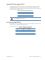
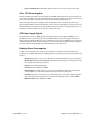
PCIe/104 Type 2 Bus (CN1 - Top)
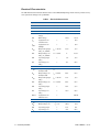
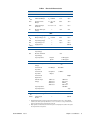
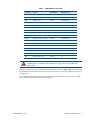
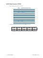
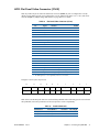
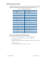
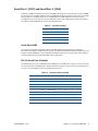
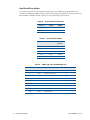
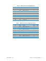
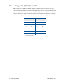
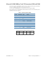
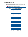
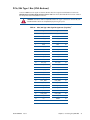
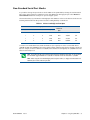
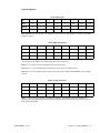
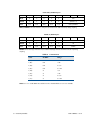
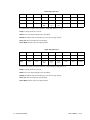
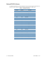
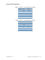
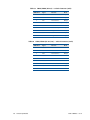
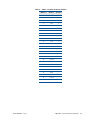
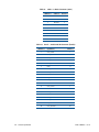
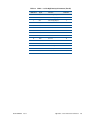
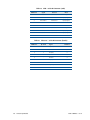
Connector CN1 carries the signals of the PCIe/104 PCIe bus. These signals match definitions found in the
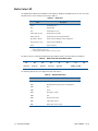
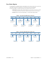
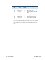
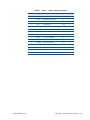
PCI/104-Express & PCIe/104 Specification Version 2.01 from the PC/104 Embedded Consortium. Table 30
lists the pinouts of the PC/104-Express bus connector.
WARNING Not all PCIe cards are compatible with the PCIe/104 Type 2 connector. Be sure that all of the
boards attached to this bus are compatible before powering the system.
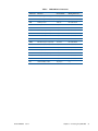
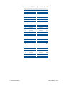
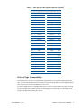
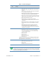
Table 30
BDM-610000075
Rev D
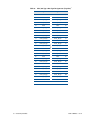
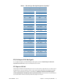
PCIe/104 Type 2 Bus Signal Assignments (Top View)1
Signal
Signal
Pin
1
USB_OC#
PE_RST#
2
3
+3.3V
+3.3V
4
5
USB_1p
USB_0p
6
7
USB_1n
USB_0n
8
9
GND
GND
10
11
PEx1_1Tp
PEx1_0Tp
12
13
PEx1_1Tn
PEx1_0Tn
14
15
GND
GND
16
17
PEx1_2Tp
PEx1_3Tp
18
19
PEx1_2Tn
PEx1_3Tn
20
21
GND
GND
22
23
PEx1_1Rp
PEx1_0Rp
24
25
PEx1_1Rn
PEx1_0Rn
26
27
GND
GND
28
29
PEx1_2Rp
PEx1_3Rp
30
31
PEx1_2Rn
PEx1_3Rn
32
33
GND
GND
34
35
PEx1_1Clkp
PEx1_0Clkp
36
37
PEx1_1Clkn
PEx1_0Clkn
38
39
+5V_Always
+5V_Always
40
41
PEx1_2Clkp
PEx1_3Clkp
42
43
PEx1_2Clkn
PEx1_3Clkn
44
45
CPU_DIR
PWRGOOD
46
47
SMB_DATA
Reserved
48
49
SMB_CLK
Reserved
50
51
n.c.
PSON#
52
+5 Volts
Pin
Chapter 3: Connecting the cpuModule
43