1
5. INSTALLATION LOCATIONS
● Avoid the following environments for installation locations:
Areas with vibration, corrosive gases, dust, water, oil, solvents, direct sunlight, radiation, a strong electric field, and/or a strong
magnetic field
● If there is any risk of a surge being induced into the power line
and/or signal lines due to lightning or other factors, a dedicated
lightning arrester should be used as protection for both this unit
and a field-installed device.
This portion is yellow.
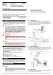
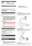
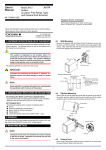
The figure below shows the JT11 with its front panel (cover) being open.
Communication
connector
Adjustment
switch
7.1 Operation Indicating Lamp
Input
6
5
4
3
Power Supply
The operation indicating lamp shows the operating status, abnormal
setting, and adjustment operating status using the adjustment switch
on the front panel.
(1) When the lamp is lit:
Power is turned on and the distributor is in the normal status provided that the selection switch is turned to the position “0.”
(2) When the lamp is flashing rapidly:
The lamp repeats the rapid flashing until the internal processing is
completed during output adjustments and the wiring resistance
correction using the adjustment switch.
(3) When the lamp is flashing slowly:
The lamp repeats the slow flashing until the distributor regains its
normal status when the following abnormalities occur.
● Abnormal parameter setting
● The selection switch is turned to the positions other than “0.”
● Input is out of the range of -10 to 110%.
● OFF of RJC and error of RJC.
3
4
RJC
5
6
7
7
8
1
2
Output
1
2
Operation indicating
lamp
Selection
switch
Wiring should be connected to the terminals on the socket of the product. The terminals for external connections are of M3.5 screws. Use
crimp-on terminal lugs for connections to the terminals.
● Recommended cables: A nominal cross-sectional area of 0.5 mm2
or thicker for signal cables, and that of 1.25 mm2 or thicker for
power cables.
8
Part number: A1128HT
7. PART NAMES OF FRONT PANEL
To avoid the risk of an electric shock, turn off the power
supply and use a tester or similar device to ensure that no
power is supplied to a cable to be connected, before carring
out wiring work.
L
Part number: A1167HT
The style of JT11 is indicated on the nameplate attached to the frontlface of the main unit.
WARNING
N
The RJC sensor for the JT11
with former style
Not available for the JT11 with
style of 2.00 or higher
This portion is red.
6. EXTERNAL WIRING
GND
The RJC sensor for the product
(For the JT11 with style of 2.00 or
higher)
IMPORTANT
● The power line and input/output signal lines should be
installed away from noise-generating sources. Other
wise accuracy cannot be guaranteed.
● The grounding resistance must be 100 Ω (JIS Class D
grounding). The length and thickness of the grounding
cable should be as short and thick as possible. Directly
connect the lead from the ground terminal (terminal no.
6) of the product to the ground. Do not carry out daisychained inter-ground terminal wiring.
● Use of the product ignoring the specifications may
cause overheating or damage. Before turning on the
power, ensure the following:
(a) Power supply voltage and input signal value applied to
the product should meet the required specifications.
(b) The external wiring to the terminals and wiring to ground
are as specifications.
● Do not operate the product in the presence of
flammable or explosive gases or vapors. To do so is
highly dangerous.
● The RJC sensor may be damaged if an excessire force
is applied. When attaching the RJC sensor, be sure not
to pull it or not to bend the crimp-on terminal lugs.
● The product is sensitive to static electricity; exercise care in
operating it. Before you operate the product,
touch a nearby metal part to discharge static electricity.
The product works normally when the RJC sensor “A1167HT”
(see the figures below) is connected to the socket. If another
RJC sensor is connected, it does not work normally. Make
sure that the correct RJC sensor is connected referring to the
figures below.
7.2 Communication Connector
The communication connector is used when setting the parameters
through a PC (VJ77 Parameter Setting Tool) or the Handy Terminal.
JHT200
Handy Terminal
JUXTA communication cable with
5-pin connectors (F9182EE)
[Provided with VJ77, JHT200]
Modular jack conversion
adapter (E9786WH)
[Provided with VJ77]
Dedicated adapter (E9789HA)
[Provided with VJ77]
Dedicated cable (E9786WK)
[Provided with VJ77]
PC
7.3 Selection Switch and Adjustment Switch
The following adjustments can be made using the switches on the front
panel (selection switch and adjustment switch) without the dedicated
setting tool (see Section 7.2, "Communication Connector").
The adjusted value is stored about 1 second after operating the adjustment switch. Also when the rotating direction of the adjustment switch
is changed, the adjusted value becomes effective about 1 second after
the change.
2
IM 77J03T01-01E
1st Edition
Apr.19 2004-00