1
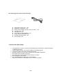
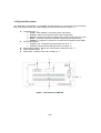
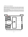
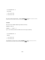
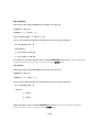
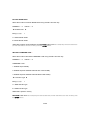
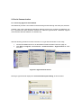
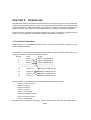
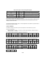
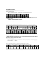
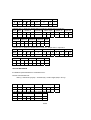
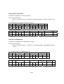
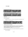
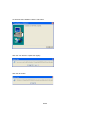
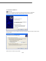
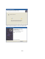
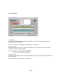
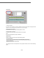
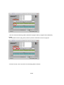
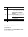
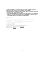
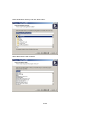
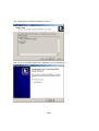
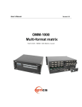
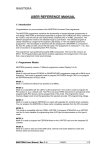
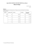
Edition 2a
ODM1818
18:18 DVI Matrix Routers
USER MANUAL
1/59
TABLE OF CONTENTS
CHAPTER 1.
INTRODUCTION AND INSTALLATION
1.1 Notice for safe usage
1.2 Physical Description
1.3 EDID Control and Configuration
CHAPTER 2.
COMMUNICATIONS SETUP
2.1 Setting Router ID of ODM1818
2.2 Front Panel control
2.2.1 CREATE Mode
2.2.2 PREVIEW Mode
2.2.3 CANCEL Mode
2.2.4 FUNCTION Mode
2.3 Serial Communication
2.4 Ethernet Control
2.5 USB Control
CHAPTER 3.
OPERATIONS
3.1 Front Panel Operation
3.2 Command Line Operation
3.3 Web Control Panel Operation
3.4 Proprietary PC Software Operation
3.4.1 Installation of PC Program Application
3.4.2 Installation of USB Driver
3.4.3 Operation by PC Program
Appendix
A. Trouble shooting
B. Feature
C. Specification
D. Firmware downloading
2/59
3/59
CHAPTER 1. INTRODUCTION AND INSTALLATION
The ODM1818, 18X18 DVI Matrix Router is a high speed cross switcher of 18 DVI inputs and 18 DVI
outputs. Having a ruggedized metallic enclosure, the ODM1818 gives applicability to harsh
environments. The key features are;
Eighteen (18) DVI single-link inputs and output
Up to WUXGA (1,900x1,200) pixel resolution at 60Hz refresh ratio, having 1.65Gbps
transmission bandwidth
EDID management – flexible adaptation to power management of overall systems
Direct readout from connected displays
Preset to input ports
Long distance extension of DVI input and output by Optical DVI cables or modules
Reclocking of R,G,B of DVI inputs and outputs
Various Control Interfaces;
Front panel key input
Commands input through RS232, LAN, and USB
Graphic user interface over Ethernet
Graphic user interface using Proprietary PC software in the shipping group
Hierarchical connection of multiple ODM1818 up to 3 levels to widen the number of
display connection or source connection
DIP switch setting for differentiating multiple use of DS-1818M II over RS232 connection
IP setting for Ethernet – point-to-point and local network control
4/59
The shipping group consists of the followings;
Hard plastic case to carry: 1 set
Mainframe of ODM1818: 1 set
AC/DC power adaptor (12V/10A, AC110V-240V): 1 set
AC power cord: 1 set
User Manual: 1 set
CD storing PC control software: 1 set
A plug – B plug USB cable: 0.5m
Firmware download cable: 1 set
RS-232 cable: 1set
1.1 Notices for Safe Usage
If the equipment is used in a manner not specified by the manufacture, it might be impaired
in inability of recovery.
Use the assigned power cord or power adaptor in the shipping group.
Connect the power cord to the normal and safe outlet.
Keep the unit away from the liquid, magnetic and combustible substances.
Do not place heavy weights on the unit.
Move away from noisy environments like vibration or impact.
Do not install the unit vertically.
Do not disassemble the unit by user’s own discretion.
When any malfunction or breakdown occurs, contact us promptly.
5/59
1.2 Physical Description
The ODM1818 is mountable on 19” standard rack with brockets. On front panel are some function
keys, input-output buttons and a status display window placed as shown in Figure 1-1.
CONTROL keys: ①
Create - Start updating or configuring input-output setup
Preview - Show current status of input-output configuration
Cancel – Destruct all outputs configured with a input or Reject any key inputs
Enter - Accept key inputs and complete configuring input-output setup
Function - Configure IP for Ethernet, set baud rate for RS232 and set EDID:
Input-output Buttons:
Eighteen (18) illuminated LED type buttons for input: ②
Eighteen (18)) illuminated LED type buttons for output: ③
Status window display - display the control status in 20x4 text mode: ④
Power ON/OFF button: ⑤
Reset button – Restart: Push with a needle pen ⑥
Figure 1-1 Front Panel of ODM1818
6/59
All input, output, interface and power connections are placed on the rear panel and are featured as
follows;
Eighteen (18) single link DVI inputs - female type: ①
Eighteen (18) single link DVI outputs - female type: ②
DIP switch - 8 bits to set identifier in case of multiple connection of ODM1818: ③
USB B type receptacle port: ④
RS 232 Serial port - selectable of baud rates: ⑤
10/100 Base Ethernet Port: ⑥
Download Port - firmware download: ⑦
DC power receptacle: ⑧
Figure 1-2 Rear Panel of ODM1818
7/59
1.3 EDID Control and Configuration
EDID (Extended Display Identification Data) is a data structure provided by a display to describe its
capabilities to a graphic card. It is what enables a PC to know what kind of monitor is connected. It
includes manufacturer name, product type, phosphor or filter type, timings supported by the display,
display size, luminance data and (for digital displays only) pixel mapping data. Once the graphic
source reads it out (usually done in booting PC), the EDID helps it know information of best-fit data
format for a connected monitor.
Besides of configuration of inputs and outputs, the ODM1818 supports EDID configuration to store
any wanted EDIDs to an EEPROM of each input by front key control, command codes and web
control panel setting. The ODM1818 gives two choices for EDID setting out of fixed factory EDID and
direct readout-store EDID of any targeted display. The factory default setting is UXGA (1,600x1,200)
at 60Hz for all inputs.
INPUT 1~18
OUTPUT 1~18
WRITE EDID
EEPROM1
EEPROM2
EEPROM3
.
.
.
.
EDID
INTERFACE
CONTROL
.
.
.
.
EEPROM16
EEPROM17
EEPROM18
Figure 1-3 Concept drawing of EDID setting and working in ODM1818
8/59
As shown in the concept drawing, once you do EDID configuration, then each EDID is stored in
EEPROM at the front of DVI input and the video sources could read out each EDID in the EEPROM.
The beauty of working is that the video sources enable to start reading EDID in boot-up even though
the ODM1818 and connected displays are not powered on yet.
Connection of Optical DVI cables and modules for long distance extension
The ODM1818 supports connection of Optical DVI cables or modules to the inputs and outputs.
We strongly recommend not using copper DVI cables over 3 m (10ft) extension, but using fiber-optic
DVI products.
Initializing ODM1818 and Installation Guide
INITIALIZATION
Plug a adequate AC power cord in the shipping group to the AC/DC power adaptor and plug the DC
cord to the +12VDC connector on the rear panel while caring the arrow mark on the connector of the
DC cord. Push POWER button on the front panel then you could see;
Red LED lit on the button and Initializing … 18X18 DVI Matrix on the display window and
sweeping Green and Red lights on the Input and Output buttons respectively. Finally shows
USER MODE on the display window, which means being ready to accept commands.
RACK MOUNTING
Before installing cables, the ODM1818 has to be mounted on the rack. On both front faces of the
side chassis are two holes tapped to screw L-shape plates to the rack.
CONTROL CONNECTIONS
Commands and functions of the ODM1818 are accomplished through the RS-232C and Ethernet
connection. USB interconnection is valid only with Proprietary Windows PC software on CD in the
shipping group.
RS-232C Control
Connect the ODM1818 to a video controller or PC with a RS-232C cable having D-sub 9 pin males’
connectors.
Ethernet Control
Connect the ODM1818 to a video controller or PC with a cable having RJ 45 connectors.
Direct connection of PC or video controller to the ODM1818: Use an Ethernet crossover cable.
The PC which is connected to the network is typically configured to have a
dynamic IP address by a network DHCP server. If the PC connects directly to
the ODM1818, the server in your network is not available for making addressing the PC.
The PC should be manually set in a static IP address. Refer to the Setting the
PC IP address on page 14.
LAN connection of the ODM1818: Use a straight Ethernet cable.
The ODM1818 is configured at the factory with the default IP address,
192.168.0.88. Before connecting to your network, verify if it is valid on the
network.
The IP address can be reconfigured by front key buttons or command lines
over RS 232, Ethernet and USB.
9/59
CHAPTER 2
COMMUNICATIONS SETUP
2.1 Setting Router ID of ODM1818
If you have multiple routers of ODM1818 with a video controller or PC for control, at first each
ODM1818 should be identified with DIP switch setting, located on the rear panel marked in Router ID.
They are consisted of 8 digits, representing One (1) at the up position and Zero (0) at the down
position, being able to set in a range of 000 to 255. The factory default setting is 255.
Example Setting
In case of 000
In case of 001
In case of 255
All command codes are required to have the router ID in its header. For more details, refer to the
command codes instruction in Chap. 3.2.
2.2 Front Panel Interface
Without connection of any Video controller or control PC, all communications with the ODM1818 are
able to work with the front key inputs.
Notice that CREATE, PREVIEW and CANCEL of control keys are toggled in Activate and Deactivate
modes. The ENTER functions accept and select and save pre-activities. The FUNCTION key has
setting of several features and each push shows each feature in a sequential iterating mode. In
Function mode, pushing ENTER means saving the setting whatever you change or not. But, pushing
other control buttons makes escape from the FUNCTION mode. Before starting keying, make sure
that the display window shows USER MODE.
2.2.1 CREATE Mode
It enables to configure connection of inputs and outputs to be cross-switched as you wish.
At first, push CREATE button to make it activate in Red lit, and then you could see the current
configuration on the display window. Following it, push one of any input buttons to make it activate in
Green light and then you can see lighting in Red on currently configured outputs and at the same
time can see the configuration on the display window.
Select single or multiple outputs of any output buttons to make them lit in Red. Output buttons are
toggled in ON (selected) or OFF (reject).To complete configuring outputs for an input, push ENTER
and then save the setting and return to the User Mode.
10/59
Sequentially push another input button and match any outputs for the input until all inputs are
configured. Pushing any of CREATE, PREVIEW or CANCEL shows the current configuration of
in-out match.
2.2.2 PREVIEW Mode
It shows configuration of in-out match. The PREVIEW button is toggled. Push the button to light in
Orange and shows the in-out connection diagram on the display window. While keeping in Red lit,
push any input button and then light connected outputs in Red for the input lit in Green. If pushing
ENTER button, swing lights of output buttons for each input sequentially.
During the swing light, the mode is changed by user mode when users push the Cancel key.
2.2.3 CANCEL Mode
It enables cancel the configuration of outputs for each input. Push CANCEL button and then show
the current configuration on the display window. Now, push an input button to be canceled and then
light the selected input in Green and its configured outputs in Red. Pushing ENTER button makes
complete the process.
2.2.4 FUNCTION Mode
Function operation
Move the step of Menu by control Create & Function key
Flow chart as follows;
18 : 18 = Monitoring -> IP Setting -> Subnet Mask Setting -> Gate way Setting -> Baud rate Setting
-> Command Type -> Edid Save Setting -> Factory Setting
Edited data will be store at each mode using by Preview key. (Except monitoring)
To complete the process, press the enter key for saving & renew the data.
SELECT ONE OF INPUTS FOR MONITORING
This process is not a must, but your option in case of making sure a video source. At first, connect a
display to the MONITORING port and any video sources to the inputs on the rear panel.
Push the Create & Function key for select the monitoring mode, then the display window on the
front panel shows;
(Notice) This matrix does not store the connection data on DB. User can use the monitoring function
at the Monitoring Mode. Connection will be disconnect when user change another function mode or
user mode.
11/59
◀ MONITOR MODE ▶
Input Channel :
You could push any input buttons to be monitored among eighteen (18) input keys. Push ENTER
button to finish the process.
SETTING FOR COMMUNICATION MODE
IP ADDRESS
Select the mode for IP ADDRESS using Create & Function key.
Input 17 and 18 buttons make the Under Bar move to left and right, respectively.
NUMBER 0 : INPUT 10
NUMBER 1 ~ 9 : INPUT 1 ~ 9
◀ NETWORK INFO
▶
Local IP:
C : 192. 168. 000. 088.
E : 192. 168. 000. 088.
192. 168. 000. 088 is preset in factory. Pressing PREVIEW button store as a temporary and then
finishes the process and back to the user mode by push the ENTER button.
SUBNET MASK
Select the mode for SUBNET MASK using Create & Function key.
NUMBER 0 : INPUT 10
NUMBER 1 ~ 9 : INPUT 1 ~ 9
Input 17 and 18 buttons make the Under Bar move to left and right, respectively.
12/59
◀ NETWORK INFO
▶
Subnet Mask:
C : 255. 255. 255. 000.
E : 255. 255. 255. 000.
255. 255. 255. 000 is preset in factory. . Pressing PREVIEW button store as a temporary and then
finishes the process and back to the user mode by push the ENTER button.
GATEWAY
Select the mode for SUBNET MASK using Create & Function key.
NUMBER 0 : INPUT 10
NUMBER 1 ~ 9 : INPUT 1 ~ 9
Input 17 and 18 buttons make the Under Bar move to left and right, respectively.
◀ NETWORK INFO
▶
Gateway:
C : 192. 168. 000. 001.
E : 192. 168. 000. 001.
192.168.000.001 is preset in factory. Pressing PREVIEW button store as a temporary and then
finishes the process and back to the user mode by push the ENTER button.
13/59
MAC ADDRESS
Select the mode for MAC ADDRESS using Create & Function key.
NUMBER 0 : INPUT 10
NUMBER 1 ~ 9 : INPUT 1 ~ 9
ASCII CHARACTOR A ~ F : INPUT 11 ~ 16
Input 17 and 18 buttons make the Under Bar move to left and right, respectively.
◀ NETWORK INFO
▶
Mac Address:
C : 00. AA. BB. CC. DD. EE.
E : 00. AA. BB. CC. DD. EE.
00. AA. BB. CC. DD. EE is preset in factory. Pressing PREVIEW button store as a temporary and then
finishes the process and back to the user mode by push the ENTER button.
Port Number
Select the mode for PORT NUMBER using Create & Function key.
NUMBER 0 : INPUT 10
NUMBER 1 ~ 9 : INPUT 1 ~ 9
Input 17 and 18 buttons make the Under Bar move to left and right, respectively.
◀ NETWORK INFO
▶
UDP Port :
C : 03000
E : 03000
03000 is preset in factory. Pressing PREVIEW button store as a temporary and then finishes the
process and back to the user mode by push the ENTER button.
14/59
RS 232C BAUD RATE
Select the mode for RS 232C BAUD RATE using Create & Function key.
NUMBER 1 ~ 4 : INPUT 1 ~ 4
◀ Set Baud rate ▶
Entry(1,2,3,4) :
1
C : BAUD RATE 19200
E : BAUD RATE 19200
19200 bps is highly recommended to set. PREVIEW button store as a temporary and then finishes the
process and back to the user mode by push the ENTER button.
SETTING COMMAND TYPE –
Select the mode for SETTING COMMAND TYPE using Create & Function key.
NUMBER 1 ~ 3 : INPUT 1 ~ 3
COMMAND TYPE :
1. ODM1818 (RT CODE)
2. ODM1818 (DATA LENGTH 2BYTE OLD TYPE CODE)
3. ODM1818 (DATA LENGTH 3BYTE NEW TYPE CODE)
◀ Command Type ▶
Entry(1,2,3,4) :
1
C : ODM1818 SE Type
E : ODM1818 SE Type
ODM1818 is preset in factory.
PREVIEW button store as a temporary and then finishes the process and back to the user mode by push
the ENTER button.
15/59
SETTING EDID AT INPUTS
Select the mode for BAUD RATE TYPE using Create & Function key
NUMBER 1 ~ 18 : OUTPUT 1 ~ 18
Page Move : INPUT
15, 16
Cursor move : INPUT 17, 18
Other Channel status : Using Page move key (Each page show the status of 6 channel)
EDID control : Page key and cursor key make the under bar move to Edit window (Input & Output)
After move that push the Output channel.
◀
I
O
:
:
0
P
1
R
E
D
0
P
2
R
I
D
0
P
3
R
S
A
0
P
4
R
V
▶
E
0
P
5
R
0
P
6
R
Saving the data using by key of PREVIEW. Push ENTER button to finish the process.
FACTORY MODE
Select the Factory mode by control Create & Function key
You can choose operate Factory mode or not with pop-up.
You have to press ‘Enter’ key again after press ‘Input 1’ key to operate Factory Mode.
Since operate Factory Mode, all parameters will removed and reset to the factory out setting.
It will move to User Mode after finish Factory Mode operation.
You can move to User Mode directly without Factory Mode operation by press ‘Enter’ key
after press ‘Input 1’ key.
16/59
2.3 Serial Communication
2.3.1 Launching HyperTerminal Window
The ODM1818 provides a command line interface being executed through the serial port, RS-232C.
Consider a PC running the Microsoft Windows operating system as a controller for ODM1818. The
PC is provided with serial emulation software so called as HyperTerminal. ODM1818 supports
communication with this software in an efficient way.
Take the following procedure to make connection of a HyperTerminal window on PC ready.
1.
2.
Connect the ODM1818 to a PC as described in section RS-232C Control on page 16
Click Start > Programs > Accessories > Communications > HyperTerminal to make
executed.
Figure 2-1 HyperTerminal Access
Running a HyperTerminal displays the Connection Description Dialog, as shown below.
17/59
Figure 2-2 Connection Description Dialog
3.
In the dialog, enter a name and choose an icon. Clicking OK displays the Connect To dialog box.
Figure 2-3 Connect To Dialog
4.
In the Connect To dialog box, ignore the Country, Area Code and Phone Number fields.
In the Connect Using field, choose the available COM port to which the serial cable from
18/59
5.
ODM1818 is connected.
Click OK to show the COM Properties dialog box.
Figure 2-4 COM Properties Dialog
6.
7.
8.
9.
Configure the PC to the DS-1818M II default settings as follows;
Bits per second (baud rate): 19200 (recommended) or others
Data bits: 8
Parity: None
Stop bits: 1
Click OK to display the HyperTerminal window.
Make sure that the communication of ODM1818 is ready by pressing ENTER.
Send command set. (Refer to Chap. 3.2)
19/59
2.3.2 Telnet
Telnet is a user command and an underlying TCP/IP protocol for accessing remote computers.
Through Telnet, an administrator or another user can access someone else's computer remotely. On
the Web, HTTP and FTP protocols allow you to request specific files from remote computers, but not
to actually be logged on as a user of that computer. With Telnet, you log on as a regular user with
whatever privileges you may have been granted to the specific application and data on that computer.
LAUNCHING TELNET SESSION
With the IP address of the PC set above, a Telnet session can be started.
1.
2.
From the PC Start menu, select Run.
2. In the Open dialog box, type command as shown below.
Figure 2-6 Run Window
20/59
3.
4.
Click OK to open the Windows command window.
At the prompt in the command window, type:
telnet <ip_address> 8000
where <ip_address> stands for the IP address of the ODM1818.
For example, if it keeps the default IP, type as follows;
telnet 192.168.000.088 8000
…. and press ENTER
Figure 2-7 Telnet connected
21/59
2.4 Ethernet Control
The ODM1818 can be controlled through the 10/100 base Ethernet port using either graphic user
interfaces or a command line interface. The graphic user interfaces use both of a standard web
browser such as Microsoft Internet Explorer and a proprietary PC software. The physical connection
of ODM1818 can be made on the standard LAN or directly in the peer-to-peer way. The command
line interface uses a Telnet session to a private port.
To make ODM1818 connect through the Ethernet port, it should be set to have a unique, static IP
address. The default IP from factory is 192.168.000.088. To acquire a valid IP in your LAN network,
contact your network manager to avoid IP conflict. If change of the default is required, refer to
Changing the ODM1818 Matrix Router IP Address in Chap. 2.2.4 for instruction.
SETTING THE PC IP ADDRESS
If PC is directly connected to the ODM1818 through the 10/100 Base Ethernet port, a static address
should be configured in PC. Following instruction shows how to assign it;
1.
2.
3.
4.
Use an Ethernet crossover cable or hub to connect directly between the Ethernet port of the
ODM1818 and that of a PC.
From the PC Start menu, select Control Panel.
In the Control Panel, select Network Connections.
In the Network Connections, make a right click on Local Area Connection and select
Properties tab. The Local Area Connection Properties window is shown as follows;
22/59
Figure 2-5 Local Area Network Properties Window
5.
6.
7.
Scroll and select Internet Protocol (TCP/IP) and click on Properties.
In the Internet Protocol (TCP/IP) Properties, click the Use the following IP address radio button.
Enter an IP address being compatible with the current IP address of the ODM1818. For
example, in case of factory default IP, 192.168.000.088, the PC IP address should be
chosen as 192.168.000.nnn, where nnn ranges 000 to 255 except 088.
Figure 2-6 Setting an PC IP address
8.
Close all windows opened during this procedure.
2.5 USB CONTROL
The control of ODM1818 through USB connection is only valid with the proprietary PC software, but
not with command line interface. For its device installation and instruction to use, refer to the
Proprietary PC Software Operation in Chap. 3.4.
23/59
CHAPTER 3
OPERATIONS
The ODM1818 could be operated in various interfaces, Front Panel Key Inputs, communicating with
command lines, graphic interfaces on web control panel (WCP) and proprietary PC software through
RS 232C, Ethernet, or USB. All functions are executed in a basis of command line interface, but
graphic interfaces on the WCP or the PC software make more efficient to operate the ODM1818.
Firmware and PC software are managed according to versions in release or upgrades and are
shown how to upgrade in the firmware and software management in Appendix B.
3.1 Front Panel Operations
Refer to Chap. 2.2, for the details front keys function. To show how to operate, examples for some
cases are explained below;
For example, if you have eighteen displays with three different types of EDID to be set and want to
configure connection of inputs and outputs like below;
Port No.
Input
Output
1
Source 1
Display 1 (EDID type A)
2
Source 2
Display 2 (EDID type B)
3
Source 3
Display 3 (EDID type B)
--------------------------------------------------------------------------------------------------------------------------------------------------15
Source 15
Display 15 (EDID type B)
16
17
18
Source 16
Source 17
Source 18
Display 16 (EDID type C)
Display 17 (EDID type C)
Display 18 (EDID type A)
The input-output configuration drawing arrows represents connecting as below;
Input 1 to Output 1 and 15,
Input 2 to Output 2,
Input 3 to Output 3,
Input 4 to Output 5,
Input 15 no connection
Input 16 to Outputs 16 and 17,
Input 17 to Output 18, and
Input 18 no connection
Operation has to be executed in two steps. The first is EDID setting, which has each EDID data of
24/59
displays stored into EEPROM at each input front as configured in the above. The last is Input-Output
Configuring, to make cross-switch as configured in the above.
1. For the first step of EDID setting, selecting the mode for EDID SAVE mode using Create &
Cancel key until displaying EDID save in the front LCD window.
◀
I
O
:
:
0
P
1
R
E
D
0
P
2
R
I
D
0
P
3
R
S
A
0
P
4
R
S
A
0
0
4
9
V
▶
E
0
P
5
R
0
P
6
R
2. Set the configuration as shown in below;
◀
I
O
:
:
0
0
1
5
E
D
0
1
2
6
I
D
0
1
3
7
V
▶
E
0
0
5
1
0
P
6
R
Note if input has no output connection, EDID will not save. (PR is displayed)
Note that in case that a source connects two or more different displays, you should
select only one EDID to work for your configuration.
3. Push ENTER key to make the process complete.
4. Confirm the message to successfully execute storing the EDID as configured;
Note that the stored EDID setting keeps until re-taking the EDID setting process, even
though the ODM1818 is powered on and off repeatedly.
5. For the last step, input-output configuring, push CREATE key to display the existing input-output configuration below;
◀ Create Mode ▶
Input Channel :
6. Push the input 1 numeric key to make it turned in Green and then see the below in the LCD
25/59
window;
◀ Create Mode ▶
Input Channel :
7. Enter the number 1 and 4 as a selection of outputs for the given input and push ENTER key
and then turn back to the user mode.
Note that it is possible to select the output channels for any input as many as wished.
8. Repeat the process from 5 to 7 for other inputs like 2, 3, 4, … , and 8. Push PREVIEW and
then show the below;
◀ Preview Mode ▶
Input Channel :
Note that the input numeric keys could be activated only one-by-one and the output
numeric keys are toggled.
Note that to make any output keys activated (turn in Red) or deactivated shows the
change on the LCD window at the same time.
Note that the process of input-out configuring executes at the moment of pushing
ENTER key.
26/59
3.2 Command Line Operation
Command line interface is accomplished through RS-232C or Ethernet ports. Setting procedures for
those ports are referred to SEREAL CONTROL and ETHERNET CONTROL.
The commands are coded in ASCII and HEXA. All descriptions are shown in Table 3.1. A command
line constitutes of a string of ASCII or HEXA codes in a series as below;
Start (1 Byte) + Router ID (3 Bytes) + Command (1 Byte)
+ Data Length (3 Bytes)
+ Output Number (2 Bytes) + Input Number (2 Bytes)
+ Output Number (2 Bytes) + Input Number (2 Bytes) + …..
+ End (1 Byte)
A command line allows executing only one command. Multiple commands require executing multiple
strings having each command per a string.
All strings starts with Start byte.
To set Router ID, refer to 2.1 Setting Router ID of ODM1818 on page 10, to be selectable in a range
of 000 to 255, written in 3 bytes.
Data Length represents the number of all bytes afterward it. And it is determined by the number of
channels in which involved in the command line. Input Ch Number should follow Output Ch
Number, which is designated in a pair.
A command line closes with End byte.
27/59
Table 3.1 Descriptions of Command Codes
Command Format
Start
Router ID
Command
ASCII
*
Variable
HEX
0x2A
Variable
Description
Header Code
Router ID Value
Create
0
0x30
Connects or disconnects the
selected input and output channels
Preview
1
0x31
Previews the connections
of all channels
Cancel
2
0x32
Cancels the connection
of selected channel
Upload Data Request
3
0x33
Upload the connections information
to controller
Rolling
4
0x34
Rotates the input and output
connection
Upload Router ID
5
0x35
Uploads the Router ID to controller
Rolling Stop
6
0x36
Stops the rolling command
Check Connection
7
0x37
Uploads the right or wrong
of all connections
8
0x38
Uploads the connection status of
selected channel
Baud rate Setting
Read Output Device
EDID
@
0x40
Changes Baud rate for RS-232
A
0x41
Reads EDID from attached display
Default EDID Setting
B
0x42
Restores factory set EDID on
EEPROM
Read Input EEPROM
EDID
C
0x43
Reads EDID from EEPROM
EDID Write
D
0x44
Reads EDID from display and writes
to EEPROM
Edit EDID Write mode
EDID Data
E
F
0x45
0x46
Edits EDID Write mode
Send divided data by two
Monitoring
G
0x47
Sets the monitoring channel
Variable
Variable
Variable
0x21
Selected Output Ch
Selected Input Ch
Tail Code
Upload One Channel
Data Request
Data Length
Output Ch
Input Ch
End
Byte
1
3
1
3
2
2
1
As a response of command line input to ODM1818, it returns any of the following ACK signals to the
controller shown in Table 3.2 if it is not specified.
28/59
Table 3.2 Description of Acknowledge(ACK) Signals
Acronym
Bytes
ASCII Codes
Description
Error
1
0x05
Router received the irregular data packet
RX Complete
1
0x06
Router received the regular data packet
Job Complete
1
0x07
Completed the operation per command
Connection OK
1
0xA0
Connection has been successfully done
After sending command codes, ACK will be returned.
If the command codes are successfully done, 0x06, 0x07 will be returned. But if it is failed, 0x05 will
follow it by return. Some command codes have special ACK and it is described under the each
example command code below.
The followings illustrate example codes for various applications to be utilized on HyperTerminal for
RS-232 and on Telnet for TCP/IP.
CREATE COMMAND
It enables to configure connection of inputs and outputs to be cross-switched as you wish.
Format of command line:
Start (*) + Router ID (3 byte) + Command (0) + Data Length (Variable) + Output ch (2 byte) +
Input ch(2 byte) + … + End(!)
Ex. 1> One (1) channel connection of Output Ch1 and Input Ch1
Start
Router ID
Command
Data Length
Output ch
Input ch
End
ASCII
*
0
0
0
0
0
0
4
0
1
0
1
!
HEX
2Ah
30h
30h
30h
30h
30h
30h
34h
30h
31h
30h
31h
21h
Ex. 2> One (1) channel disconnection of Output Ch1 by setting “0” on the input channel bytes.
Start
Router ID
Command
Data Length
Output ch
Input ch
End
ASCII
*
0
0
0
0
0
0
4
0
1
0
0
!
HEX
2Ah
30h
30h
30h
30h
30h
30h
34h
30h
31h
30h
30h
21h
Ex. 3> Two (2) channels connection: Output Ch1
Input Ch8 & Output Ch 8
Start
Router ID
Command
Data Length
Output ch
Input Ch1
Input ch
ASCII
*
0
0
0
0
0
0
8
0
1
0
8
HEX
2Ah
30h
30h
30h
30h
30h
30h
34h
30h
31h
30h
38h
Output ch
Input ch
End
29/59
0
8
0
1
!
30h
38h
30h
31h
21h
Ex. 4> Eighteen (18) channels direct –through connection
Start
Router ID
Command
Data Length
Output ch
Input ch
ASCII
*
0
0
0
0
0
7
2
0
1
0
1
HEX
2Ah
30h
30h
30h
30h
30h
33h
32h
30h
31h
30h
38h
Output Ch
Input Ch
…
Output Ch
Input Ch
Output Ch
Input Ch
END
0
2
0
2
...
1
7
1
7
1
8
1
8
!
30h
32h
30h
32h
…
31h
37h
31h
37h
31h
38h
31h
38h
21h
PREVIEW COMMAND
It shows configuration of all input-output match.
Format of Command line:
Start (*) + Router ID (3 byte) + Command (1) + Data Length (000) + End (!)
Byte
Start
Router ID
Command
Data Length
End
ASCII
*
0
0
0
1
0
0
0
!
Hex
2Ah
30h
30h
30h
31h
30h
30h
30h
21h
CANCEL COMMAND
It enables to cancel the configuration of outputs for each input.
Format of Command Line:
Start (*) + Router ID (3 byte) + Command (2) + Data Length (variable) + Input ch (2 byte) +
End (!)
Ex> Input channel 1 disconnection
Byte Start
Router ID
Command
Data Length
Input Ch
End
ASCII
*
0
0
0
2
0
0
2
0
1
!
Hex
2Ah
30h
30h
30h
32h
30h
30h
32h
30h
31h
21h
30/59
UPLOAD DATA REQUEST
It enables to upload the connection data to the controller.
Format of Command Line:
Start (*) + Router ID (3 byte) + Command (3) + Data Length (000) + End (!)
Byte
Start
Router ID
Command
Data Length
End
ASCII
*
0
0
0
3
0
0
0
!
Hex
2Ah
30h
30h
30h
33h
30h
30h
30h
21h
Sending Upload Data Request command to router let ODM1818 respond ACK signal to controller
in a format as follows;
0x06(06h) + Connection DATA + 0x07(07h)
The Connection Data represents the connection information of router
1) Connection Data of ODM1818 for a connection of 1-1, 2-2, 3-3 … … 16-16, 17-17, 18-18
Byte
Start
Router ID
Command
Data Length
Output Ch
Input Ch
ASCII
*
0
0
0
3
0
7
2
0
1
0
1
Hex
2Ah
30h
30h
30h
33h
30h
33h
32h
30h
31h
30h
31h
Output Ch
Input Ch
0
2
0
2
30h
32h
30h
32h
…
Output Ch
Input Ch
Output Ch
Input Ch
END
........
1
7
1
7
1
8
1
8
!
……
31h
37h
31h
37h
31h
38h
31h
38h
21h
ROLLING COMMAND
It enables to rotate the input at fixed output. This function is useful to check the connection status of
all inputs and outputs by changing them orderly.
Format of Command Line:
Start (*) + Router ID (3 byte) + Command (4) + Data Length (Variable) + Output ch (2 byte) +
Input ch (2 byte) + … + End (!)
Ex> To rotate three (3) inputs 1, 2, and 3 on three (3) outputs 1,2, and 3.
1) Output Ch1
Input Ch1, Output Ch2
Input Ch2, Output Ch3
Input Ch3
Byte
Start
Router ID
Command
ASCII
*
0
0
0
4
0
1
2
Hex
2Ah
30h
30h
30h
34h
30h
31h
32h
31/59
Data Length
Output
Ch
0
1
30h
31h
Input Ch
0
1
30h
31h
Output Ch
Input Ch
Output Ch
Input Ch
End
0
2
0
2
0
3
0
3
!
30h
32h
30h
32h
30h
33h
30h
33h
21h
2) Output Ch1
Byte Start
Input Ch2, Output Ch2
Input Ch3, Output Ch3
Input Ch1
Router ID
Command
Data Length
Output Ch
Input Ch
ASCII
*
0
0
0
4
0
1
2
0
1
0
2
Hex
2Ah
30h
30h
30h
34h
30h
31h
32h
30h
31h
30h
32h
Output Ch
Input Ch
Output Ch
Input Ch
End
0
2
0
3
0
3
0
1
!
30h
32h
30h
33h
30h
33h
30h
31h
21h
3) Output Ch1
Byte Start
Input Ch3, Output Ch2
Input Ch1, Output Ch3 => Input Ch2
Router ID
Command
Data Length
Output Ch
Input Ch
ASCII
*
0
0
0
4
0
1
2
0
1
0
3
Hex
2Ah
30h
30h
30h
34h
30h
31h
32h
30h
31h
30h
33h
Output Ch
Input Ch
Output Ch
Input Ch
End
0
2
0
1
0
3
0
2
!
30h
32h
30h
31h
30h
33h
30h
32h
21h
UPLOAD ROUTER ID
It enables to upload Router ID to controllers or PC.
Format of Command Line:
Start (*) + Router ID (3 byte) + Command (5) + Data Length (000) + End (!)
Byte
Start
ASCII
*
Router ID
0
0
Command
0
5
Data Length
0
0
0
Hex
2Ah 30h 30h 30h
35h
30h 30h 30h
If the Router ID is 015, you will receive ACK signal as follow.
Byte Start
Router ID
Command End
ASCII
*
0
1
5
5
!
Hex
2Ah
30h
31h
35h
35h
21h
32/59
End
!
21h
ROLLING STOP
It Stops the Rolling command.
Format of Command Line:
Start (*) + Router ID (3 byte) + Command (6) + Data Length (000) + End (!)
Byte
Start
Router ID
Command
Data Length
End
ASCII
*
0
0
0
6
0
0
0
!
Hex
2Ah
30h
30h
30h
36h
30h
30h
30h
21h
CHECK CONNECTION
It enables to check status of all connections.
Format of Command Line:
Start (*) + Router ID (3 byte) + Command (7) + Data Length (000) + End (!)
Byte
Start
Router ID
Command
Data Length
End
ASCII
*
0
0
0
7
0
0
0
!
Hex
2Ah
30h
30h
30h
37h
30h
30h
30h
21h
Sending Check Connection command to router let ODM1818 respond ACK signal to controller in a
format as follows;
Good connection: 0xA0 (A0h)
Bad connection: 0x05 (05h)
UPLOAD ONE CHANNEL DATA REQUEST
It enables to upload the connection status of a selected input channel.
Format of Command Line:
Start (*) + Router ID (3 byte) + Command (8) + Data Length (002) + Output ch (2 byte) + End
(!)
In case of input 6
output1 connection
Byte Start
Router ID
Command
Data Length
Output Ch End
ASCII
*
0
0
0
8
0
0
2
0
1
!
Hex
2Ah
30h
30h
30h
38h
30h
30h
32h
30h
31h
21h
The ACK signal would be
Byte Start
Router ID
Command
Data Length
Input Ch
End
ASCII
*
0
0
0
8
0
0
2
0
6
!
Hex
2Ah
30h
30h
30h
38h
30h
30h
32h
30h
36h
21h
33/59
READ OUTPUT DEVICE EDID
It enables to read EDID from connected display.
Format of Command Line:
Start (*) + Router ID (3 byte) + Command (A) + Data Length (002) + Output ch (2 byte) + End
(!)
Ex.> Read EDID from a Display connected to Output 1
Byte Start
Router ID
Command
Data Length
Output ch
End
ASCII
*
0
0
0
A
0
0
2
0
1
!
Hex
2Ah
30h
30h
30h
41h
30h
30h
32h
30h
31h
21h
The ACK signal would be
Byte Start
ID
ASCII
*
0
Command
0
0
A
Data Length
2
5
8
Hex
2Ah 30h 30h 30h
41h
32h 35h 38h
EDID (256Byte) contains output display 1 EDID information.
Output Ch
EDID (256Byte)
End
0
1
…
!
30h
31h
00h…xxh
21h
READ INPUT EEPROM EDID
It enables to read EDID stored on EEPROM of an input.
Format of Command Line:
Start (*) + Router ID (3 byte) + Command (C) + Data Length (002) + Input EEPROM (2 byte)
+ End (!)
Ex.> Read EDID stored on EEPROM of Input 2
Byte Start
Router ID
Command
Data Length
Input EEPROM
End
ASCII
*
0
0
0
C
0
0
2
0
2
!
Hex
2Ah
30h
30h
30h
43h
30h
30h
30h
30h
32h
21h
The ACK signal would be
Byte
Start
ASCII
*
Router ID
0
0
Command
0
C
Data Length
2
5
8
Input
EEPROM
0
2
Hex
2Ah 30h 30h 30h
43h
32h 35h 38h
30h
EDID (256Byte) contains EDID information which was in EEPROM 2.
34/59
31h
EDID
(256Byte)
…
00h…xxh
End
!
21h
EDID WRITE
It enables to read EDIDs from connected displays and write them to each EEPROM.
Format of Command Line:
Start (*) + Router ID (3 byte) + Command (D) + Data Length (Variable) + EEPROM 1 (2 byte)
+ EEPROM 2 (2 byte) + … + End (!)
Variable in Data Length is determined by multiplying 2 bytes to the maximum number of input
channels. In case of ODM1818, it is 16 bytes, multiplying 2 bytes to 8 inputs.
The 2 bytes in EEPROM # represents the output number connected to a targeted display, the EDID
of which would be stored to the EEPROM #. For example, 03 in EEPROM 2 means putting the EDID
of output 3 display into EEPROM 2. The value, 00 in EEPROM # means no updating on EEPROM.
Ex.> Sets (Output 1 display
INPUT1 EEPROM, Output 3 display
Byte
Start
ASCII
*
0
0
0
D
0
3
6
0
1
0
3
Hex
2Ah
30h
30h
30h
44h
30h
31h
36h
30h
31h
30h
33h
EEPROM 3
Router ID
……..
Command
EEPROM 18
Data Length
INPUT 2 EEPROM)
EEPROM 1
EEPROM 2
END
0
0
…
…
0
0
!
30h
30h
…
…
30h
30h
21h
DEFAULT EDID SETTING
It restores factory set EDID on EEPROM.
Format of Command Line:
Start (*) + Router ID (3 byte) + Command (B) + Data Length (000) + End (!)
Byte
Start
Router ID
Command
Data Length
End
ASCII
*
0
0
0
B
0
0
0
!
Hex
2Ah
30h
30h
30h
42h
30h
30h
30h
21h
BAUD RATE SETTING
It enables to change baud rate for RS-232C.
Format of Command Line:
Start (*) + Router ID (3 byte) + Command (@) + Data Length (002) + Baud Rate (variable) +
End (!)
The default baud rate is 19,200, which is selectable as the following options;
01 for 19,200bps
02 for 38,400bps
35/59
03 for 57,600bps
04 for 115,200bp
Ex.> Sets the baud rate by 38,400bps.
Byte Start
ID
Command
Data Length
Baud Rate
End
ASCII
*
0
0
0
@
0
0
2
0
2
!
Hex
2Ah
30h
30h
30h
40h
30h
30h
30h
30h
31h
21h
ACK would be same as command code for BAUD RATE SETTING
Byte Start
ID
Command
Data Length
Baud Rate
End
ASCII
*
0
0
0
@
0
0
2
0
2
!
Hex
2Ah
30h
30h
30h
40h
30h
30h
30h
30h
31h
21h
MONITORING
It sets the monitoring channel.
Format of Command Line:
Start (*) + Router ID (3 byte) + Command (G) + Data Length (002) + Monitoring Data (2 byte)
+ End (!)
Ex.> Sets Input ch 2 as a Monitoring channel
Byte Start
ID
Command
Data Length
Monitoring Data
End
ASCII
*
0
0
0
G
0
0
2
0
2
!
Hex
2Ah
30h
30h
30h
47h
30h
30h
32h
30h
32h
21h
3.3 Web Control Panel Operation
The web control panel (WCP) gives a graphic alternative to command line interface. ODM1818
supports to be operated by a standard web browser. Microsoft Explorer is highly recommended to
use. Before running the web browser, confirm that the set-up for Ethernet connection is
pre-performed as guided in the …. Page13.
.
At first, run the web browser and enter the ID address into the URL address line.
For example, if the IP address sets to the factory setting, 192.168.000.088, then type the following
entry into the URL address line.
http://192.168.000.088
36/59
3.4 Proprietary PC Software Operation
3.4.1 Installation of PC Program Application
Follow the instructions below to install the ODM1818 software into your PC. Insert the ODM1818
software CD into your PC. If the CD does not automatically run, click
Start >Run. Enter X:\ ‘ODM1818-install.exe, where X is the letter of your CD drive.
The following screen will open. Then, click NEXT button.
Select the destination directory path. The default destination directory is
C:\Program Files\ ODM1818. Click 'Install' button For Software Installation.
37/59
To terminate the installation Click the 'Ok' button.
Click the 'Yes' button to update the registry.
Click the 'Ok' button.
38/59
3.4.2 Installation of USB Driver
Windows XP
Please turn on the Router Power after connecting PC and the Router over USB cable.
Please push the "NEXT" button after checking the option button as shown below.
Insert enclosed CD into the CD-ROM and select the searching Location and click the "NEXT" button
as shown below.
Please click the "Continue Anyway" button.
39/59
Please complete the installation by clicking the "FINISH" button.
40/59
3.4.3 Operation by PC program
1) Initialize the PC program.
- Check the communication cable (RS-232C, LAN or USB) and turn on the router.
- Double click the PC program.
- Set the same Router ID number on the PC program as the DIP switch setting on the rear panel of
router.
- Router initializes and verifies the connection state of communication cable.
- If everything is normal, the message 'connection is completed successfully' appears on the
Edit-Box, and then it loads up switching-pattern from router and display it on status display area
immediately.
- In case of wrong cable connection, COM port or Router ID, the message ‘Device Not Found’ will be appeared
on the status display area. Then, check those again. To check COM port, push right side of ‘RS-232C’ button
and make sure the COM port number and baud rate are set properly. Default baud Rate is19200.
- Now user can create or update the switching-pattern.
- The Message Box asks for Over Write (Y) or Insert (N) of switching-data.
- Press ‘Y’: Overwrite the old switching-data.
- Press ‘N’: Create new switching-pattern. Allocate the new pattern name and click “Accept” button.
- After the updating or creating the switching-pattern, "Job Completed” will follow on status display
area.
41/59
2) Control Buttons
1) Cre (Creat)
Function: It has the same function as the Create-Button on the router front panel. It setups the
Input-Output channel connection.
Process: Cre. Button
Input Button
Output Button
Ent. Button
2) Pre (Preview)
Function: It has the same function as the Preview-Button on the router front panel. It checks the
current Input-Output connection states.
Process: Pre. Button
Pre. Button
Input Button (Single Mode),
Ent. Button (Auto Mode)
3) Can (Cancel)
Function: It has the same function as the Cancel-Button on the router front panel. It disconnects the
Input with Output.
Process:Can. Button
Input Button
Ent. Button
42/59
3) File menu
1. Router ID Setting
It controls router temporary by removing hardware router ID number when user forgot router ID
number or can not change the dip switch due to far remote location.
2 Download Patten to Device
It downloads current input-output channels pattern to router.
3 Upload Pattern from Device
It uploads current input-output channels pattern to PC program.
4 Exit
It terminates the application program, ODM1818.
4) Edit Pattern
a) Edit: It modifies the current input-output switching pattern.
- Click the edit button.
- The current input and output names and switching pattern will be shown.
- User can assign new input and output names and switching patter separately.
- Click the Save Button.
- Modified switching pattern will be saved.
- By posing the mouse on the input button on PC program as below, user can review switching
pattern.
43/59
- User can check the switching-pattern database at program folder (c:\program files\ ODM1818).
b) Add
- Set the pattern name as (My_Grace) and than push the Add button on the PC program.
- Once this is done, user can see the new switching-pattern as below.
44/59
- Click the edit button then user can edit switching-pattern and input-output names.
c) Modify
- Select the switching-pattern, to be modified.
- Write down the new pattern name in the combo box.
- Click the Modify button.
- It is almost same as ‘SAVE AS’ in window program.
d) Delete
- Select the pattern name, to be deleted.
- Click the Delete button
- The selected pattern name will be disappeared in the combo box list.
5) Rolling Function
It makes user rotate input sources at output displays repeatedly at regular intervals. It is useful
function to check the all input and output connections.
User can select output channels to be rolled using the Check Box.
If output channel is not connected to any input channel, Check Box would not be checked.
Output channel must be more than 2 channels.
45/59
For example, if the current switching-pattern is same as step 1 as below and want to rotate the input
channels on output 1, 2, 3, 4, 5. Please check the rolling box 1, 2, 3, 4, 5 and set the interval you
want.
Then lowest channel Input LED and connected output channel LED on Router will be turned on. (In
this case input 1 and output 1 be tuned on)
Single Rolling
- Push the 'Single' Button.
- The output will be changed repeatedly at specified interval from step 1 to step 6 and be finished
automatically.
- Even though the Rolling is on going, if you push the 'Stop' Button, the Rolling will is stopped.
- The output image will be remained on current state.
Unlimited Rolling
- It rotates the input continuously on the output display until the user pushes the 'Stop' Button.
- If you push the "stop" Button, at any time, rolling will be stopped, and it does not affect the
pre-saved switching-pattern
- If you want to quit the rolling, please select new pattern.
46/59
6) EDID Setting
It provides several EDID handling function
-
Store EDID
-
Read EDID from output device
-
Read EDID from output device and store it in input EEPROM
-
EDIT user defined EDID
-
Restore default EDID (in all input channel)
-
One touch storing (in all input channel)
-
Storing EDID by individual selection
-
Basic EDID structure: EDID Block 0 [128 bytes]
But, the most useful and important methods are described here. For more specialized handling method, please
contact the technical support.
Push the Files Button, and go to EDID setting.
Then select the Write EEPROM Write tab at upper side.
a) Read the OUTPUT DEVICE EDID and save it in selected EEPROM
- Check OUTPUT DEVICE EDID
- Check the EEPROM# and select the OUTPUT # on right side one by one
- Push the write EEPROM button to save
b) Set Default EDID
- By pushing Set Default EDID button all of EEPROM will have factory set EDID.
47/59
A. Trouble shooting
Problem
Symptom
Remedy
Power
No Power LED
Check the power cord is correctly connected to the
ODM1818 and to an AC power source and that the power
switch is in the ON position
Check the input output DVI cables are correctly connected
to each port of ODM1818 and double check the input
output connection configuration you want.
Output
No output present
The display is not capable of the resolution sent to it.
Check the compatibility of EDID in the EEPROM and
attached displays
When a single input is routed to multiple outputs, EDID
priority may not yield compatible resolution. So set EDID
priority to minimum resolution.
EX> Input 1
Output 1 (UXGA) & Output 2(SXGA)
If EEPROM 1 store the display 1 EDID (UXGA), the
display 2 (SXGA) will not works due to resolution limit.
The source has stopped sending a graphic signal.
Check that input source status by connecting it to available
monitor without the ODM1818.
B. Features
This unit is designated to make cross-switch between the 18 DVI inputs and the 18 DVI outputs in a
way of any of 18 inputs to one or multiple outputs. Chassis is hardened enough to be applicable in
harsh environments like staging, control rooms and military.
1) Enable to connect the maximum 18 independent displays.
2) Comply with DVI-HDCP standard.
3) Each output port can be used as a Signal-Distributor.
4) Support Windows PLUG & PLAY function.
5) Offer various control interfaces like Front-Key input, RS232C, USB and TCP/IP (UDP) communication.
6) Easy program download using ISP Interface.
48/59
7) Fulfill real-time display of running status on 20x4 LCD and with illuminated LED type keys.
8) Be rack-mountable with solid 19 inch standard RACK TYPE CASE (3U).
9) Support real-time Hot_Plug Detection and program each EDID to connected DVI sources as per
user’s specification. (EDID programming option)
9) Offer 3 options to set EDID to connected DVI sources; (1) direct reading as per in-out switching
configuration, (2) execute pre-one-time connection of a target display to each source, and (3)
program EDID to the input on the PC software in the shipping group.
C. Specification
1) Input & Output Video Signals Type: TMDS (Transient Minimized Differential Signal)
2) DVI Signal Bandwidth: Maximum 1.65Gbps
3) Resolution: VGA (640x480) ~ WUXGA (1920x1200), 480~1080i and 1080p
4) RS232 baud rates: 19,200bps ~115,200bps
5) LAN Port: 10/100 base
6) USB: Hi-speed USB 2.0
7) AC/DC Power Supply: 110~240V/1.5A, 50~60Hz, DC12V/5A
8) Size: 484 x 240 x 264mm (W x D x H) *For 18X18
9) Weight: 11.5Kg *For 18X18
49/59
D. Firmware downloading
1. Installation of the Ponyprog2000
Follow the instructions below to install the PonyProg2000 software into your PC. Insert the
ODM1818 software CD into your PC. Go to Downloader directory in CD and execute setup.exe.
The following screen will open. Then, click NEXT button.
Check the ‘I accept the agreement’
50/59
Define destination directory and click ‘Next’ button.
Select Start Menu Folder as below.
51/59
Click ‘Install’ button to install the software in your PC
Click ‘Finish’ then PonyProg2000 will be installed in your PC successfully.
52/59
2. Download of Firmware
Turn on Router and connect Router (to Download port) and PC( to Parallel port) over firmware
download cable.
Execute PonyProg2000.exe and click ‘OK’.
Click ‘OK’ button for calibration.
53/59
Select ‘AVR micro’ as below.
Select ‘Atmega128’ as below.
54/59
Select ‘Interface Setup’ in Setup menu as below.
Set I/O port as below and click ‘OK’ button
55/59
Select ‘Security and Configuration Bits’ in Command menu.
Click the ‘Read’ button and make sure option is set as below.
If the option is not same as below click the ‘Clear All’ to reset and check it again.
Then click ‘Write’ button and click ‘Read’ button and check the option is same and below again.
56/59
Select ‘Open Program (FLASH) File’ in File menu and select new firmware to download.
Select ‘Write Program(FLASH)’ in Command menu.
57/59
Click ‘OK’ button then it starts downloading and verifying continuously.
.
Click ‘OK’ to terminate the downloadin.
Now the Router is operated under the new firmware.
58/59
Opticis Locations
Opticis Co., Ltd.
#501 Byucksan Technopia, 434-6,
Sangdaewon-Dong,
Chungwon-Ku, Sungnam City,
Kyungki-Do, 462-120, South Korea
Tel: +82 (31) 737-8033
Opticis North America Ltd.
330 Richmond Street, Suite 100,
Chatham, Ontario, Canada N7M 1P7
Tel: (519) 355-0819
Fax: (519) 355-0520
Fax: +82 (31) 737-8079
For order support, please contact your Distributor or Reseller.
For technical support, check with the Opticis web site www.opticis.com
Email: [email protected]
59/59