1
INCHWORM ROBOT
User Manual
CONTENTS
PART 1 : Inchworm Robot
1. Introduction
2. Features
3. Control
4. Actions
PART 2 : CPU Board
1. Placement Diagram (Silkscreen)
2. Circuit Diagram
3. Parts List
PART 3 : Software Tools
1. AVR Development Program Installation
2. How to use WinAVR GCC
3. How to use PonyProg2000
PART 4 : Robot Operation
1. Compile and Download
2. R/C servomotor (HES-288)
3. Adjusting motors
PART 5 : Source Codes
1. Init.c
2. Function.c
3. Inter.c
4. Motion.c
5. Inchworm.c
PART 1 : Inchworm Robot
1. Introduction
INCHWORM ROBOT is fashioned after an inchworm and utilizes four RC servomotors. Its CPU is an
ATmega8 with an In-System Programming (ISP) function. Thus, the user can download a program to the
robot without a ROM Writer. A free C-compiler (Microrobot AVR GCC) is provided. In building this kit the
user learns how to control multi RC servomotors. In addition, the free C-compiler and ISP function helps
beginners.
2. Features
. ATmega8 (Atmel AVR series, 16MHz X-tal(16 MIPS) but internal 8MHz RC Oscillator setting is required for
the RC Servo Source Example. Refer to “Security Bit Settings for ATMega Family.pdf” for the setting. ).
. Four R/C servomotors.
. 16 R/C servos connectable (16 I/O port pins).
. Controls up to 8 R/C servomotors at the same time.
. C source code.
. Free Windows C compile (WinAVR AVR GCC).
. Included ISP downloader.
. On board piezo Buzzer.
3. Control
The Inchworm Robot’s CPU board has sixteen I/O port pins and can control 8 servomotors at the same time.
The Inchworm Robot has an ATmega8 CPU board as a controller. ATmega8 CPU has three internal
counters. The CPU board generates up to eight periodic pulses using the timers. The periodic pulses control
R/C servomotors.
4. Actions
Six actions are available with the provided sample program.
l
Crawling forward
l
Raising and nodding the head
l
Crawling backward
l
Lifting and wagging the tail
PART 2 : BOARD
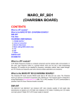
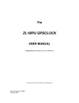
1. Placement Diagram(Silkscreen)
Fig 1. ATmega8 Servomotor control board silkscreen.
5
4
3
2
1
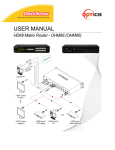
2. Circuit Diagram
VCC
VCC
U1
D
VCC
VCC
PD0(RXD)
PD1(TXD)
PD2(INT0)
PD3(INT1)
PD4(TO)
PD5(T1)
PD6(AIN0)
PD7(AIN1)
4
5
R4
10K
18
20
21
/RESET
C
S3
+
Tack
30
31
32
1
2
9
10
11
29
3
6
C3
1uF
PC5(ADC5/SCL)
PD0(RXD)
PC4(ADC4/SDA)
PD1(TXD)
PC3(ADC3)
PD2(INT0)
PC2(ADC2)
PD3(INT1)
PC1(ADC1)
PD4(TO/XCK)
PC0(ADC0)
PD5(T1)
PD6(AIN0)
PD7(AIN1) PB6(XTAL1/TOST1)
28
27
26
25
24
23
VCC
GND
8
PB7(XTAL2/TOST2)
17
16
15
14
13
12
GND
VCC
19
22
R1
470
C1 20pF
7
PB5(SCK)
AVCC
PB4(MISO)
AREF
PB3(MOSI/OC2)
GND
PB2(SS/OC1B)
PB1(OC1)
PC6(RESET)
PB0(ICP)
ADC6
ADC7
D
PC5(ADC5)
PC4(ADC4)
PC3(ADC3)
PC2(ADC2)
PC1(ADC1)
PC0(ADC0)
Y1
16MHz
PB5(SCK)
PB4(MISO)
PB3(MOSI)
PB2(/SS)
PB1(OC1)
PB0(ICP)
BZ1
BTG-47
D2
LED
C2 20pF
PB5(SCK)
PD0(RXD)
PD1(TXD)
PD2(INT0)
PD3(INT1)
PD4(TO)
PD5(T1)
PD6(AIN0)
PD7(AIN1)
PC0(ADC0)
PC1(ADC1)
PC2(ADC2)
PC3(ADC3)
PC4(ADC4)
PC5(ADC5)
PB2(/SS)
PB1(OC1)
C
J2
SERVO HEADER 48
ATMega8/TQFP
3 X 8 Header 100mil
VCC
2
1
B
VCC
S1
C5
SLIDE
5267-2P
J1
2
1
C4
+
5045-2P
J5
104
VCC
R5
10K
R2
470
1
J4
VCC
D3
PB0(ICP)
D1
LED
C6
104
VCC
LED
+
R3
S2
Tack
2
VCC
470
100uF/10V
PB3(MOSI) 10
8
/RESET
6
PB5(SCK)
4
PB4(MISO) 2
J3
+
+
+
+
+
+
+
+
+
+
B
9
7
5
3
1
CON10AP
2
1
5267-2P
www.microrobot.com
A
Title
Size
A
5
4
3
Date:
Document Number
<Doc>
2
A
MR-Servo4433
Sheet
Rev
1.0
1
1
of
1
3. Parts List
NO
1
2
3
4
5
6
7
8
9
10
11
12
13
14
15
16
17
18
19
20
21
22
23
24
Reference
C1, C2
C3
C4
C5, C6
D1, D2, D3
J1
J2
J3
J4, J5
R1, R2, R3
R4, R5
SP1
S1
S2, S3
U1
Y1
Part name
Capacitor
”
”
”
LED
Connector
”
”
”
Resistor
”
BUZZER
S/W
”
MCU
X-TAL
Printed Circuit
Board(PCB)
Servomotor
Battery Holder&
Power Connector
Pin head Screw
Nut
Flat head Screw
Downloading
Adapter
Ribbon Cable
Value
30pF
1uF
100uF/10V
104(0.1uF)
RED 3 ø
5045
HEADER PIN(Male)
CON10AP
5267
470Ω
10K
BTG-47
SLIDE S/W
Tack S/W
ATmega8/TQFP
16MHz
Qty
2
1
1
2
3
1
1
1
2
3
2
1
1
2
1
1
1
Remark
Ceramic Condenser
Electrolytic Condenser
Electrolytic Condenser
Monolithic Condenser
5V Power Part
SERVO HEADER 48PIN
HIF3F/10PIN
Battery Power Part
PIEZO
AVR Microcontroller
ATS type
Main PCB
HES-288
4
5051-2P
1
AA size * 4
4
12
4
3ø
3ø
3ø
1
1
1 meter
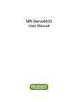
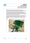
Fig 2.1 Downloading Adaptor
Fig 2.3 Battery Holder & Power Connector
Fig 2.2 Ribbon cable
PART 3 : Software Tools
1. AVR Development Program Installation
AVR Development Tools
There are many different kinds of development tools for AVR microcontrollers. Atmel, the AVR CPU
manufacturer, provides some AVR development tools free. WinAVR GCC is a free Windows C-compiler.
Wavrasm : AVR assembler, Atmel.
AVR Studio : AVR Emulator/Simulator, Atmel.
AVR ISP : ISP downloading program, Atmel.
PonyProg2000 : ISP downloading program, Lancos. (Recommended)
WinAVR GCC : C-compiler, GNU. (Recommended)
System requirements for AVR development tools
l
Windows 9X/ME or NT/2000/XP
l
Pentium-133 or higher
l
At least 4 Mbytes of RAM
l
CD-ROM Drive
AVR ISP installation:
Run setup.exe in the CD’s avr_isp folder.
WinAVR GCC installation
Refer to “How to use WinAVR for Microrobot AVR Products(Eng).pdf”.
2. How to use WinAVR Gcc
Refer to “How to use WinAVR for Microrobot AVR Products(Eng).pdf”.
3. How to use PongProg2000
Refer to the ‘PonyProg Manual for Microrobot AVR Products.pdf’and the ‘Security Bit Setting for ATMega
Family.pdf’files.
PART 4 : Robot Operation
1. Compile and Download
Compile the Inchworm Robot source file and download the executable file in the following order.
l
Put four batteries into the battery holder and insert the power connector to J1 of the Main PCB.
l
Connect the downloading adapter to the PC printer port. Then connect the downloading adapter to
the CPU board by using the ribbon cable.
l
Turn on the power switch S1 on the control board. LED D1 turns on.
l
Download sample code from our website (“How to use WinAVR for Microrobot AVR
Products(Eng).pdf”).
l
Create a source folder and copy the prototype sample code, including the makefile, from the file
you’ve downloaded.
l
Type “make all” on the DOS command line platform to compile it.
l
Debug and recompile if there are any errors or warnings.
l
If there are no errors, the ‘Errors: none’message appears.
l
Run PonyProg2000.
l
Do “I/O port setup” properly. Refer to ‘PonyProg Manual for Microrobot AVR Products.pdf’.
l
Select ‘Device → AVR micro → ATmega8’.
l
Select ‘File → Open Program File’and load the hex file.
l
Select ‘Command → Program’or press Ctrl + P to start downloading. If a ‘Program Failed’ message
appears, select ‘Command → Erase’ or press Ctrl + E to erase the flash memory, and then try to
program it again.
l
Remove the ribbon cable from the CPU board and restart the board.
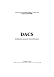
2. R/C servomotor(HES-288)
An R/C servomotor is a special type of geared motor. It has its own internal controller, which uses
feedback to control the DC motor according to the PWM (Pulse Width Modulation) position signal. The
degree of turn of the servomotor’s axle depends upon the input pulse width signal. Generally, it turns from
0° to 180°(or -90°~+90°). Therefore the servomotor does not need an encoder to get the axle’s current
position.
HES-288 is used in this Robot. It is controlled using three wires, as is general servomotor. Two wires are
for the power input and the other wire is for the PWM control signal input.
HES-288 Specification
l
Torque : 2.5 kg/cm
l
Speed : 60 degrees/0.2sec
l
Size : 41 x 20 x 35 mm (length x depth x height)
l
Weight : 42g
l
Voltage : 4 ~ 6 V
l
Operating Frequency : 50Hz~100Hz (Period:10msec~20msec)
Wire connection
Red: Vcc(DC 4~6V)
Brown: Gnd
Orange: PWM control signal input.
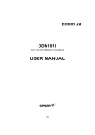
Fig 4.1
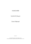
Control signal
0.7 msec : + 90°
1.5 msec : 0°(Center)
2.3 msec : - 90°
To keep the desired position (or holding torque),
the pulses must be provided every 10 ms to 20
ms.
Fig 4.2
3. Adjusting motors
When the power is on, the servos, which are connected to the board, should turn to the center but they
might not. This is because the characteristics of the individual servomotors are a little different. To adjust
each motor, the initial setting values in the source code must be changed.
l
The ATmega8 CPU board can control eight servomotors at the same time. The eight servomotors are
named SERVO_0, SERVO_1,… SERVO_7 in the program source.
l
On the upper part of the PCB, index numbers from 1 to 16 are marked for the servomotor ports. Refer
to Fig 1 above. Port numbers 1 to 8 correspond to SERVO_0 to SERVO_7 respectively. Inchworm
Robot uses the following four servomotors.
SERVO_0: Head.
SERVO_2: First body.
SERVO_4: Second body.
SERVO_6: Tail
Fig 4.3 Servo Motor Connections
l
Run your editor and open the file Inchworm.c.
l
At the beginning of the source code, there are some user definition codes.
/******************* User definition ***************************/
#define SERVO_0
(1500*8)
#define SERVO_1
(1550*8)
#define SERVO_2
(1450*8)
#define SERVO_3
(1400*8)
#define SERVO_4
(1350*8)
#define SERVO_5
(1550*8)
#define SERVO_6
(1480*8)
#define SERVO_7
(1500*8)
Note: The actual values might differ from those above.
The defined values are initial center (pulse) values for each servomotor. The center value refers to a
time constant which makes a servomotor’s axle turn to the center (0°). Refer to Fig 4.2. The user
must determine these center values by actually testing their servomotors. In the above definition,
(1500*8) means 1.5 ms, which is a typical center value. When the value is changed by ±1*8, the axle
turns approximately ±0.1125°. Repeat the process of source modification, compiling and downloading
to the robot to determine the final correct center values.
For example, when one servomotor’s axle turns 5 degrees counter clockwise past the center position,
subtract 44(=5/0.1125) from the initial value.
l
Below are some other definitions in the source file.
#define FACTOR_0
1024
#define FACTOR_1
1024
#define FACTOR_2
1165
#define FACTOR_3
1024
#define FACTOR_4
960
#define FACTOR_5
1024
#define FACTOR_6
980
#define FACTOR_7
1024
Note: The actual values might differ from the above.
The above values (constants) are used as turning factors. To make the servos turn properly, the
above values should be adjusted along with a testing process.
There is a special test mode to determine the above constants. Press and release the S3(Reset) key
while pressing the S2 key and then release the S2 key. Each servomotor should turn 90°. If not,
change the corresponding FACTOR values in the source code. For example, if the SERVO_0 turns
more than 90 degrees, reduce FACTOR_0. If the SERVO_2 turns less than 90 degrees, increase
FACTOR_2.
Fig 4.4 Servo Motor Angle Settings
l
After determining the proper values, press the S3 (Reset) key to cause the robot to lie straight. Press
the S2 key to start the robot working.
PART 5 : Source Codes
Be aware that the following source code assumes that the CPU crystal is 8MHz.
l
Inchworm.c : Main program.
l
io.h : Header file which has AVR CPU’s registers and I/O pin definitions.
l
signal.h : Interrupt vectors functions and interrupts vector table definitions.
l
init.c : Basic initialization.
l
function.c : Delay, buzzer and switch functions.
l
motion.c : Servomotor control functions.
l
inter.c : Interrupt routine functions.
1. Init.c
void port_init(void)
{
outp( 0xfe, DDRB );
outp( 0xff, DDRC );
outp( 0xff, DDRD );
outp( 1, PORTB );
outp( 0, PORTC );
outp( 0, PORTD );
//LSB of the port B = input pin, the other pins = output pin.
//Set all PORTC pins to output.
//Set all PORTD pins to output.
//Set the bit0 of the Port B to use the internal full-up resistor.
}
Initializes ports.
void motor_init(void)
{
outp(4, TCCR0);
outp(0, TCCR1A);
outp(1, TCCR1B);
// TIMER_0 CK/256 -> 1=32usec
// CTC1 clear, TIMER_1 CK/1 -> 8=1usec
outw(OCR1A, 0xffff);; // 65535 -> (65535/8)usec = 8.192msec
}
Initializes two timers to generate continuous pulses with a constant period (20 ms), which are used to
control the servomotors.
MCU main clock is 8 MHz (1/8 us). The timer0’s prescaler is set to 256. This means that the timer0 clock is
32 us (1/8 us * 256). Timer1 uses the main clock (1/8 us) without prescaling.
void motor_enable(void)
{
outp(178,TCNT0);
outw(TCNT1L, 0);
cbi(TIFR, TOV0);
sbi(TIMSK, TOIE0);
// 256-178=78 -> 78*32usec=2.496msec
// clear TOV0 : Timer0 Overflow Flag clear
// set TOIE0 : Timer0 overflow Interrupt enable
cbi(TIFR, OCF1A);
// clear OCIF1 : Timer1 Output Compare A Mach Flag clear
sbi(TIMSK, OCIE1A);// set OCIE1A : Timer1 Output Compare A Mach Interrupt Enable
}
Sets time-constant to the timer0 and enables timer0 interrupt. Even if the timer0 interrupt is enabled, the
timer0 interrupt will not occur until the global interrupt bit is enabled.
void motor_disable(void)
{
outw(TCNT1L, 0);
outp(0, TCNT0);
outp( 0, PORTD );
cbi(TIMSK, OCIE1A);// clear OCIE1A : Timer1 Output Compare Interrupt disable
cbi(TIMSK, TOIE0); // clear TOIE0 : Timer0 overflow Interrupt disable
}
Function to disable the servomotors.
void motor_zero(void)
{
int i;
Init(0)=SERVO_0;
Init(1)=SERVO_1;
Init(2)=SERVO_2;
Init(3)=SERVO_3;
Init(4)=SERVO_4;
Init(5)=SERVO_5;
Init(6)=SERVO_6;
Init(7)=SERVO_7;
Factor(0)=FACTOR_0;
Factor(1)=FACTOR_1;
Factor(2)=FACTOR_2;
Factor(3)=FACTOR_3;
Factor(4)=FACTOR_4;
Factor(5)=FACTOR_5;
Factor(6)=FACTOR_6;
Factor(7)=FACTOR_7;
for(i=0; i<8; i++)
{
Deg(i)=Speed(i)=0;
Pulse(i)=Init(i);
}
}
Copies user adjusted (defined) constants to the variables. The constants can be used directly instead of
being copied to the variables. However, for the upgrade version the variables are used. In the upgrade
version, the variables may be also filled out with constants from the PC.
void system_init(void)
{
port_init();
motor_init();
motor_zero();
}
System initialization.
2. Function.c
void delay(int ticks)
{
while(ticks--);
}
// 1msec UNIT delay function
void delay_1ms(unsigned int i)
{
word j;
while(i--)
{
j=2000; // 8Mhz
while(j--);
}
}
1 ms based delay function. For example, to make a 1 sec time delay, call delay_1ms(1000). This function
does not consider other interrupts. This means that other interrupts during the delay function can make the
delay time longer.
void buzzer(void)
{
word i;
for(i=0; i<50; i++)
{
BUZZER_ON;
delay(BUZ_DLY1);
BUZZER_OFF;
delay(BUZ_DLY1);
}
for(i=0; i<50; i++)
{
BUZZER_ON;
delay(BUZ_DLY0);
BUZZER_OFF;
delay(BUZ_DLY0);
}
}
Makes a buzzing sound using the BTG-47 buzzer. The BTG-47 is frequency (pulse) activated.
void until_switch_intput(void)
{
loop_until_bit_is_clear(PINB, 0);
loop_until_bit_is_set(PINB, 0);
}
Push button switch S2 input function, which waits until the S2 key is pressed and released.
3. Inter.c
In the source, two different interrupts are used. The interrupts are exclusive. This means, when one
interrupt service routine is served, the other one must wait.
SIGNAL(SIG_OVERFLOW0)
{
outw(TCNT1L, 0);
outp(178,TCNT0);
// 256-178=78 -> 78*32usec=2.496msec
sbi(PORTD, No);
if( Pulse(No) > (Init(No)+Deg(No)*71+(Speed(No)/2)) )
Pulse(No)-=Speed(No);
else if( Pulse(No) < (Init(No)+Deg(No)*71-(Speed(No)/2)) )
Pulse(No)+=Speed(No);
else Flag_motor&=~(1<<No);
outw(OCR1A, Pulse(No));
sbi(TIMSK, OCIE1A); // set OCIE1 : Timer1 Output Compare Interrupt enable
No++;
No&=0x07;
cbi(TIFR, TOV0);
// clear OCIE1 : Output Compare Flag1 clear
}
SIGNAL(SIG_OUTPUT_COMPARE1A)
{
outp(0, PORTD);
//clear Port D
cbi(TIMSK, OCIE1A); // clear OCIE1 : Timer1 Output Compare Interrupt disable
}
Timer0 overflow interrupt occurs every 2.5 ms. In the interrupt service routine, one of eight-servomotor
control pins is activated by turns. This means each servomotor has a controlled-focus every 20
ms(2.5msec*8).
‘No’is an index variable that indicates the port number to be serviced. The ‘No’value can be set from 0 to
7. The corresponding port pin is set high and OCR1A is set to the high-pulse time variable Pulse(No). After
the set time has elapsed, the output_compare1a interrupt occurs, which makes the pulse low.
The Speed(No) value is used to control the servomotor turning speed. For example, when the Speed(No)
is set to 71, the servo turns 1°/20ms(=50°/sec).
It takes time for a servomotor to turn to its destination. The Flag_motor variable is used to check whether
the servomotors are finished turning. Flag_motor is a one-byte variable. The bit value indicates the
servomotor’s status. 1 means the motor is still turning and 0 means the turning is done.
The servomotor turns 1° when the pulse width is changed by 8.888 us. The timer1’s clock is 1/8 us. Thus
the servomotor turns 1° per 71 timer1 clock ticks.
Init(No) is the time constant that sets the servomotor’s axle at the center(0°) position.
4. Motion.c
void wait_until_move(void)
{
Flag_motor=0xff;
while(Flag_motor);
}
// Initialze with 0xff( all servos are still turning.)
// Wait until all servomotor finish turning.
Waits until all servomotors have finished turning before starting the new next action.
// Turn the servo to the absolute angle at the speed.
void absolute_deg(int no, int deg, int speed)
{
Deg(no)=(int)((long)(deg)*(long)(Factor(no))>>10);
Speed(no)=(int)((long)(speed)*(long)(Factor(no))>>10);
}
Turns the servo(no) to the absolute angle(deg) at the given speed(speed).
The shift operation(>>) is used instead of a divide operation to increase the operation speed.
The Factor(no) is used to calculate the Speed(no) as well as the Deg(no). This is because each individual
motor has different characteristics.
void same_absolute_deg(byte flag, byte dir, int deg, int speed)
{
int i;
wait_until_move();
for(i=0; i<8; i++)
{
if( flag&(1<<i) )
{
if(dir&(1<<i)) absolute_deg(i, deg, speed);
else
absolute_deg(i, -deg, speed);
}
}
}
Moves the motors( up to eight motors ) at the same time, to the same absolute angle. The angle(deg) and
the speed are applied to all enabled servomotors equally, but the direction can be selected with the dir
parameter : clockwise or counterclockwise.
<Parameters>
flag : Motor Enable flags. Each bit enables the corresponding servomotor. 1 = enable, 0 = disable.
dir : Direction flags for each motor. 1= use +deg, 0 = use -deg.
deg : Absolute angle to turn.
speed : Turning speed.
This function is used when several motors need to move to the same angle or symmetric angle.
For example,
same_absolute_deg(S0|S2|S4|S6, S2|S4, 45, speed);
-Enables motors 0,2,4 and 6.
-Motors 1 and 3 turn to the –45 degree position and motors 0 and 4 turn to the 45 degree position at the
set speed.
same_absolute_deg(S0|S2, S2, 15, speed);
-Enables motors 0 and 2.
-Motor 0 turns to the –15 degree position and motor 2 turns to the 15 degree position at the set speed.
// relative angle turning function for the each motor.
void relative_deg(int no, int deg, int speed)
{
int temp;
temp=(int)(((long)(Deg(no))<<10)/(long)(Factor(no)));
deg+=temp;
Deg(no)=(int)((long)(deg)*(long)(Factor(no))>>10);
Speed(no)=(int)((long)(speed)*(long)(Factor(no))>>10);
}
Turns motors to the relative angle at the given speed. The relative angle means the angle relative to the
current position (as opposed to the start position).
void same_relative_deg(byte flag, byte dir, int deg, int speed)
{
int i;
wait_until_move();
for(i=0; i<8; i++)
{
if(flag&(1<<i))
{
if(dir&(1<<i)) relative_deg(i, deg, speed);
else
relative_deg(i, -deg, speed);
}
}
}
This function can be used when several motors need to move to the same relative +angle or -angle. This is
the same function as the “same_absolute_deg()” except that the deg is a relative angle.
creep1_motion() : Crawling forward.
head_up__motion() : Raising and nodding the head.
creep2_motion() : Crawling backward.
tail_up_motion() : Lifting and wagging the tail.
5. Inchworm.c
void adjust_mode(void)
{
until_switch_intput();
same_absolute_deg(S4|S6, S4, 90, 100);
same_absolute_deg(S0|S2, S2, 90, 100);
buzzer();
//Buzzing sound
}
Special test mode function to adjust all servomotors. Press and release the S3 (Reset) key while pressing
the S2 key, and then release the S2 key to enter this mode. Each servomotor should turn 90°.
int main(void)
{
int i;
system_init();
buzzer();
motor_enable();
// System Initialize
// Buzzer
sei();
// Global interrupt enable
if(bit_is_clear(PINB,0))
adjust_mode();
until_switch_intput();
delay_1ms(500);
buzzer();
delay_1ms(2000);
while(1)
{
for(i=0; i<5; i++)
creep1_motion(200);
//Crawling forward
delay_1ms(1000);
head_up_motion(100);
delay_1ms(1000);
// Raising the head
for(i=0; i<5; i++)
// Crawling backward
delay_1ms(1000);
tail_up_motion(100);
delay_1ms(1000);
creep2_motion(200);
// lift the tail
}
}
Main function: Initialization, interrupt enable and robot action functions.
www.microrobot.com