1
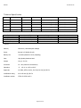
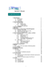
For Sales & Service Contact
2650 E. 40th Ave. • Denver, CO 80205
Phone 303-320-4764 • Fax 303-322-7242
1-800-833-7958
www.geotechenv.com
GasClam
User Manual V1.1
Part Number 25001
www.ionscience.com
Gasclam
Ion Science Ltd
Page 1 of 29
Gasclam
Ion Science Ltd
Introduction to GasClam:................................................................................................................................. 4
Getting Started: ...............................................................................................................................................5
Packing list ....................................................................................................................................................................
Turning on the Gasclam...................................................................................................................................................
Physical Characteristics....................................................................................................................................................
How the Gasclam Works ..................................................................................................................................................
Battery Change ..............................................................................................................................................................
5
5
6
7
8
Software Installation ....................................................................................................................................... 9
System Requirements...................................................................................................................................................... 9
Running the installation software ...................................................................................................................................... 9
Basic screen..................................................................................................................................................................10
Connecting ................................................................................................................................................................................................. 10
On Line Status of the Gasclam ..................................................................................................................................................................... 10
Last reading stored ..................................................................................................................................................................................... 13
Display of voltage on AD converter - ............................................................................................................................................................13
Setup ..............................................................................................................................................................13
Sampling Rate...............................................................................................................................................................14
Sample count..............................................................................................................................................................................................14
Device ID .....................................................................................................................................................................14
Venting ........................................................................................................................................................................15
Unit date and time.........................................................................................................................................................15
Erasing data memory .....................................................................................................................................................15
Switching off the unit .....................................................................................................................................................16
Update firmware............................................................................................................................................................16
Return to main screen....................................................................................................................................................16
Downloading.................................................................................................................................................................17
Viewing Data..................................................................................................................................................17
Selecting file for display..................................................................................................................................................17
Data Display Options......................................................................................................................................................18
Start-Stop data ...........................................................................................................................................................................................18
Sampling data...............................................................................................................................................................18
Selecting data channel ...................................................................................................................................................19
Scale label ....................................................................................................................................................................20
Setting auxiliary axes .....................................................................................................................................................21
Changing the scale ........................................................................................................................................................22
Time axis.................................................................................................................................................................................................... 22
Selecting displayed groups of measured values ............................................................................................................................................. 22
Export data for CSV file ............................................................................................................................................................................... 23
Print graph ................................................................................................................................................................................................. 24
Infograph ................................................................................................................................................................................................... 24
Returning to the main window ..................................................................................................................................................................... 25
Service and Calibration: ................................................................................................................................. 26
Unit calibration..............................................................................................................................................................26
Service.........................................................................................................................................................................26
User serviceable parts ....................................................................................................................................................26
Technical Specification................................................................................................................................... 27
Update Log:....................................................................................................................................................28
Page 2 of 29
Gasclam
Ion Science Ltd
Declaration of conformity
Manufacturer: Elok – Opava s.r.o.
Product: GasClam
Product description: A landfill Gas monitor designed for in-situ borehole monitoring. The entire casing is made
from solid stainless steel. The battery pack is in the upper part of the housing in a flame-proof casing. The
measuring unit consisting of four gas sensors is located in the intrinsically safe lower part of the housing.
The valves, pump and filter assembly are located at the bottom of the housing.
Directive 94/9/EC
ATEX
Identification:
II 2G Ex d ib [ib] IIB T4
Notified Body: Physical Technical Testing Institute (Czech Republic)
EC Type Examination Certificate(s): FTZÚ 07 ATEX 0105X
Standards:
PTTI EN 60079-0:2006 Electrical Apparatus for Potentially Explosive Atmospheres – General Requirement
PTTI EN 60079-1:2004 Electrical apparatus for explosive gas atmospheres. Flameproof enclosures ‘d’
PTTI EN 60079-11:2007 Explosive Atmospheres – equipment protection by Intrinsic Safety ‘I’
Directive 2004/108EC
Other Standards
KEMA EN ISO 9001:2000
On behalf of Ion Science Ltd, I declare that, on the date this product accompanied by this declaration is placed on the
market, the product conforms to all technical and regulatory requirements of the above listed directives.
Name:
Signature:
Position:
Date:
Page 3 of 29
Gasclam
Ion Science Ltd
Introduction to GasClam:
GasClam is the world’s first in-situ borehole gas monitor, suitable for the detection of a wide range of gasses commonly
found in borehole monitoring including methane (CH4), Carbon Dioxide (CO2) and Oxygen (O2). In addition to this the
GasClam can detect temperature, barometric pressure and borehole pressure.
All of these readings can be taken at user-set intervals, providing an invaluable set of data to the user. The default
setting for the Gasclam is to take readings every hour, giving it approximately three months’ operational life before it
must be connected to the Gasclam software for data retrieval. While connected to the software the settings of the
Gasclam unit can be altered including the frequency at which readings are logged by the onboard memory.
In addition to the sensors already mentioned, the Gasclam can be upgraded with a photoionisation detector (PID) for
detection of Volatile organic compounds (VOC’s), a Carbon Monoxide (CO) sensor and a water depth sensor should the
data be required.
Page 4 of 29
Gasclam
Ion Science Ltd
Physical Characteristics
Getting Started:
Packing list
Please take a little time to examine the contents of the Gasclam Package.
Item
Description
Barbs (Fitted)
Blank (NOT Fitted)
Tool for removing Barbs or Blank
Length of pipe (30cm)
Snorkel filter
Battery Allen Key
Comms cable
Start cable
Manual and software (on CD)
Rubber Collar
GasClam Unit
1.5v Duracell Batteries (Fitted)
Qty
3
1
1
3
1
1
1
1
1
1
1
2
Turning on the Gasclam
The Gasclam can be started and stopped using the remote. The remote connects to the
communication port on top of the Gasclam
.
To start the Gasclam hold the button down for two seconds, the red LED will flash rapidly
indicating the Gasclam has started and is currently going through the processes in a sampling
cycle, this equates to ‘sampling’ mode.
After the sampling processes have finished the red LED flashes intermittently, this equates to
the ‘measuring’ mode.
To stop the Gasclam press the button for two seconds, when it has stopped the LED will stop flashing, this equates to
‘sleeping’ mode
No flashing
Sleeping
Rapid flash
Sampling
Intermittent
flash
Measuring
Page 5 of 29
Gasclam
Ion Science Ltd
Physical Charact eristics
8
1.
2.
3.
4.
5.
6.
7.
8.
2
1
Communication port
Pressure transducer port
Pressure transducer port cap
Gas inlet
Gas Out
Water sensor
Pressure transducer hook
Battery compartment lid
5
4
7
6
Pictures of the Gasclam Identification plates, detailing the specifications of the unit (p.24)
Page 6 of 29
Gasclam
Ion Science Ltd
How the Gasclam Wo rks
Page 7 of 29
Gasclam
Ion Science Ltd
Battery Change
The Batteries fitted to the GasClam will last up to three months depending on type of batteries, the operating
temperature and time sequence selected.
Only change batteries in a safe area.
The battery compartment is accessed by removing the 4 screws from the battery compartment lid, see diagram. To
remove the batteries tilt the Gasclam until they fall out. Replace with the stipulated batteries positive terminal facing
down.
Optimum battery life is based on 1 hour sampling.
The Gasclam takes two D cell batteries.
NB Do not mix old and new batteries within the same unit, change both batteries at the same time. Failure
to do so will reduce battery life of the new cell fitted.
Page 8 of 29
Gasclam
Ion Science Ltd
Software Installation
System Requirements
The Gasclam software needs 30MB free space on the hard disk for installation.
The programme will run on the following platforms:
-
Windows 98
Windows 98 Second Edition
Windows 2000 service pack 3
Windows ME
Windows Server 2003
Windows XP service pack 2
Windows Vista
The programme needs .Net Framework 2.0 (x86) installed to run properly. This version is included on the software CD,
alternatively it can be downloaded from the Microsoft website.
To install .Net Framework 2.0 (x86) from the CD open the DOTNETFX folder and double click WindowsinstallerKB893803-V2-x86
The guide will take you through the installation process step by step.
Running the installation software
Insert the installation CD; the installation program should automatically begin. If this option is disabled, run the
“setup.exe” programme manually (found on the installation CD).
The guide will take you through the installation process step by step.
The default location for the Gasclam software is:
C:\Program Files\Salamander\GasClam\
Page 9 of 29
Gasclam
Ion Science Ltd
Basic screen
Connecting
The Gasclam is connected to a computer using the supplied cable between the communication port on top of the
Gasclam and a serial port on. If the computer does not have a serial port use a standard USB/Serial converter.
You can either connect the unit before or after starting the software. If the software is opened before the Gasclam is
attached the screen appears as below. In this mode the options available are to view data (see later) or to close the
application.
Page 10 of 29
Gasclam
Ion Science Ltd
On Line Status of the Gasclam
After the Gasclam is connected the screen will update (similar to below) with the device ID is displayed in box 1.
The window is divided in to 3 sections, navigation tabs (view data, download, setup and calibration), Online Status and
Last Reading Stored. This section covers the online status.
Online Status displays the current status of the unit. The default time interval for the screen to update with data from
the Gasclam is 1s, this can be changed by right clicking the software window and selecting the ‘change refresh data
interval’
Page 11 of 29
Gasclam
Ion Science Ltd
Battery status – displays battery voltage alongside a power bar, the bar changes colour according to capacity providing a
rough guide to battery life*.
Green: capacity is fine for a long sampling period
Orange: Batteries need to be replace very soon
Red: Replace batteries immediately.
*The voltage in the battery will decrease when the Gasclam is sampling due to a drain on the batteries, this is the
voltage that should be used to assess battery condition.
Note. If the battery capacity is no longer sufficient for the running of the unit during a programme the unit automatically
interrupts the cycle and switches to sleeping mode. The data is stored in the flash memory therefore the data will remain
on the Gasclam even if the batteries are completely flat. Also it is possible to replace the batteries without wiping the
memory.
Samples left –displays the remaining number of samples that can be stored in the memory. Samples taken/count – When
the Gasclam is in sleeping mode this reads ‘samples taken’ indicating how many sampling points are stored on the
memory. When the Gasclam is in sampling mode it reads ‘Sample count’ and displays the number of finished cycles and
the total number of cycles in the programme. For example, 254/4500 means that 254 cycles from 4500 required cycles
have finished. The maximum number of sample the Gasclam can store is 65000. If the Gasclam was set to hourly
sampling this equates to 5417 days.
Sampling every - shows the period between individual measuring cycles. For example, value “10 min.” means that
sampling frequency is 10 minutes.
Finish on – displays the date and time that the sampling programme will finish on.
Serial number – displays the serial number of the unit
COM port – displays which port the unit is connected to.
Status – displays the mode of the unit:
When the unit is running a programme the following modes are possible:
Sampling – the Gasclam is actively making a measurement.
Measuring – the Gasclam is between sampling periods.
When the Gasclam is not running a programme the following modes are possible:
Sleeping – the unit is not running a programme. In the mode data can be downloaded and programmed.
Clear flash – the unit is erasing flash memory data
If the Gasclam is not functioning correctly the status will read ‘undefined status,’ if this occurs contact customer services
immediately.
Page 12 of 29
Gasclam
Ion Science Ltd
“START/STOP” Button– this has several modes: The unit is in sleeping mode, to
start the Gasclam left click the button.
The unit is actively sampling, it can be stopped by left clicking the button, after
this has finished the button changes to:
The unit is between samples and the progamme can be stopped by left clicking
the button.
FirmWare – shows the firmware version in the unit. Always use the software designated for the given firmware version.
Last reading stored
The last recorded values are displayed in the ‘Last Reading Stored’ box. If the sampling cycle has started, these values
will read ‘measuring’ and are updated throughout the sampling process.
The displayed ranges of individual sensors are as follows:
Methane – 0-100% with precision of 2 decimal places
Carbon Dioxide – 0-100% with precision of 2 decimal places
Oxygen – 0-25% with precision of 2 decimal places
Gas Pressure – 0-10mbar with precision of 1 decimal place
Barometric Pressure – 0-115mbar with precision of 2 decimal places
Temperature - -50°C to +50°C with precision of 2 decimal places
Optional Water Level – 0-10m with precision of 2 decimal places
Optional CO sensor 1 PPM 0-1,000PPM or VOC 1 PPM 0-4,000PPM
The precision of the display does not correspond to the precision of the sensors, this information is included in the
technical specification section towards the end of this manual.
Display of voltage on AD converter Displaying voltage on the AD converter for some applications and testing, you have to know the voltage for the AD
converter and the value of the AD converter of the given sensor. These values are not normally displayed they can be
displayed using the menu by pressing the right button on your mouse. You can switch off the display in the same way.
Page 13 of 29
Gasclam
Ion Science Ltd
Setup
The Gasclam is programmed in the setup window, this accessed by left clicking the ‘set up’ navigation tab, the set up
window appears as below.
Rate
Sampling
The sampling rate is defined in the Set Sample Rate box, the fastest sampling rate is 3 minutes (This is how long all the
processes take), the longest 16 hours and 39 minutes.
Sample count
The number of samples to be taken can either be set to the maximum possible by clicking the ‘Always Maximum’ button
or defined by the user in the Sample count box. The maximum figure displayed is 65000 (total memory space) minus the
number of stored samples, the user defined value can be up to and including this.
The estimated date and time of the end the programme is displayed under the text button. This information is calculated
as follows: (Sample count * sample rate) + actual date and time.
Device ID
The user can specify the name of the Gasclam in the Device ID box. This is useful if there is multiple Gasclams on a site
as the borehole number can be allocated to the Gasclam. This information is used to create a filename when the data is
downloaded.
Page 14 of 29
Gasclam
Ion Science Ltd
Venting
The Gasclam has four
the Venting box (see
venting modes, the venting mode is selected in
below):
Always Closed – The vent
is always closed
Always Open – The vent
is always open.
Open once per day – The
vent opens once a day for a period of time
defined by the user
Open after every – The vent opens after a period of time defined by the user. (How long does it open for XXX)
Unit date and time
The time and date of the
and Time box, these are
unit and computer are displayed in the Date
synchronised by left clicking the Set Time tab.
The date and time is not stored when the unit is switched off or when the batteries run out or changed.
Note. The time on the unit is likely to differ from the computers if the device was programmed on a different computer
to the one it now is connected to.
Erasing data memory
Page 15 of 29
Gasclam
Ion Science Ltd
To erase all the data from the flash memory left click the Erase memory button. The status will change to ‘Clear Flash’
during this process, when this is finished to status will change to ‘Sleeping’
Warning – This process erases memory permanently. Make sure you have downloaded the data
from the unit into your computer.
Switching off the unit
If the unit is not going to be used for a long period it is recommended that it is turned off using the ‘OFF’ button, this
reduces the discharge from the batteries.
When the off button is clicked a message will appear to ask if you really want to switch off.
If the Yes button is clicked the following appears:
The Gasclam will turn off after the communication cable is disconnected, until then the main screen will appear as below:
The Gasclam will turn back on when the data cable is attached again.
Update firmware
Need to check with ION Science
Return to main screen
To return to the Gasclam software’s main window use the back button.
Page 16 of 29
Gasclam
Ion Science Ltd
Downloading
To download the Gasclam left click the ‘Download’ button. This opens a standard Window’s ‘save as’ window. The
default file name is the device ID followed by the time and date.
After choosing the file name and location the download begins when save is clicked, the length of the download will
depend upon the amount of data.
Two files are produced a .GCL which is used in the Gasclam software and .CSV file which can be opened in excel to plot
data in a suitable manner for reports etc.
Viewing Data
The data viewer is accessed via the ‘View Data’ navigation button on the main screen.
Selecting file for display
If a data file has just been downloaded the software remembers its location and can be accessed by clicking ‘open’
To access any other file click the ‘…’ button this allows you to browse through your computers folders. The last folder
that was accessed will open.
Page 17 of 29
Gasclam
Ion Science Ltd
Data Display Op tions
There are 3 data view options that can be accesses via the Start-Stop Data, Calibration Data and Sampling Data buttons,
see below:
Start-Stop data
To display the sampling log of the unit click the ‘Start-Stop’ Data button. Information regarding when and how the unit
was started and stopped, date the action was taken, memory space left and sampling frequency and how many samples
was taken is reported, see below for an example.
Note. If the Gasclam has stopped due to low battery a note indicating this will be left in the code column.
Sampling data
To display the sampled data click the ‘Sampling-data’ button. The following parameters are displayed, see example
below.
Date: in the format dd/mm/yyyy hh:mm
CH4 %: Methane % v/v
CO2 %: Carbon dioxide % v/v
O2 %: Oxygen % v/v
CO: Carbon Monoxide or VOC: Volatile Organic Compound PPM
Page 18 of 29
Gasclam
Ion Science Ltd
Dif (mbar): Differential pressure between borehole and atmosphere. If the value is negative it means the pressure in
the borehole is lower than atmospheric and if the pressure is positive it is higher than atmospheric.
Bar mbar: Barometric pressure
Temp C: Temperature in degrees Celsius
H2O Level m
Battery (V): Battery capacity in volts
It is possible to order the displayed data according to individual parameter by clicking the column header, one click
arranges them in ascending order two clicks arranges them in descending order.
To view the data in graphical form click the Graph/Data view toggle button.
Graph/Data
view toggle
button
This opens the Graph view window, shown below.
Page 19 of 29
Gasclam
Ion Science Ltd
Selecting data channel
To select a data channel click the desired parameter from the ‘Data Channel’ box, see below. Multiple parameters can be
displayed by clicking more parameters.
Page 20 of 29
Gasclam
Ion Science Ltd
Scale lab el
When displaying multiple parameters up to two y-axes can be selected using the ‘Scale-label’ drop down menu, see figure
below.
Page 21 of 29
Gasclam
Ion Science Ltd
Setting auxiliary axes
Changing the scale
The scale of the y-axes can be changed using the min and max boxes indicated below. The scale can be changed by
either using the up/down buttons next to the Min Max buttons or by typing the required value in to the field and clicking
on the box adjacent to it i.e., to change the min value type the desired value and then click in the Max box and the graph
will update.
Time axis
Time is displayed on the y-axis, this can be scrolled through using the scroll bar underneath.
Page 22 of 29
Gasclam
Ion Science Ltd
Selecting displayed groups of measured values
Page 23 of 29
Gasclam
Ion Science Ltd
Import data into External Spreadsheet
Data is provided as a CVS file and can be imported into various spreadsheets for manipulation. This is normally done
using the import function and selecting delimited and then selecting comma as the separator.
Print graph
By pressing the “Print graph” button, you can print the actual graph.
Page 24 of 29
Gasclam
Ion Science Ltd
Infograph
To display the all the values of the parameters at any particular time left clicking the graph at this point and the
Infograph box will appear, see below.
Returning to the main window
To return to the main Gasclam screen click the ‘Back’ button
Page 25 of 29
Gasclam
Ion Science Ltd
Service and Calibration:
Unit calibration
Calibration should only be carried out by an authorised Gasclam distributor.
Service
The Gasclam should be regularly serviced to ensure correct and accurate operation. It is recommended that it should be
serviced and recalibrated every xxx months.
The Gasclam is ATEX certified for use in potentially explosive areas therefore it should only be serviced by qualified
engineers. Failure to do so will invalidate the warranty.
User serviceab le parts
Inline filter:
This accessed by unscrewing the bottom section of the Gasclam, see figure.
It should be replaced regularly, certainly after a weeklong installation. The instrument should never be
operated without the filter.
Braised sections
End section,unsrew by
holding the two braised
section and turning anticlockwise
Filter
Snorkel:
The snorkel should be checked regularly, if there is any damage replace immediately
Collar:
Inspect the collar regularly, if there is any signs of damage replace immediately.
Page 26 of 29
Gasclam
Ion Science Ltd
Technical Specification
Sensor
Method/type
Range
Resolution
Accuracy
Linearity
CH4
Infrared
0-100 %
0.01 %
± 5% of reading ± 1 digit
+/- 2% FSD or 10% reading
CO2
Infrared
0-100 %
0.01 %
± 5% of reading ± 1 digit
+/- 2% FSD or 10% reading
Oxygen
Electrochemical
0-25 %
0.1 %
± 5% of reading ± 1 digit
+/- 2% FSD or 10% reading
CO*
Electrochemical
0-2,000 PPM
1 PPM
± 5% of reading ± 1 digit
+/- 2% FSD or 10% reading
VOC*
PID
0-4,000 PPM
1 PPM
± 5% of reading ± 1 digit
+/- 2% FSD or 10% reading
Environment
Barometric
Borehole
Temperature
Water depth*
Method / Type
Piezoelectric
Piezoelectric
Internal Chip
Piezoelectric
Range
800-1200 mb
-100 - +100 mb
-5°C to +50°C or 41°F to 122°F
0 – 10 m
* Optional
Memory
6300 time / date stamped readings
Power
Internal x 2 Alkaline D-cells
Battery Life
3 months (Based on hourly sampling)
Case
High Quality Stainless Steel
Weight
6 kg or 13.2 lb
Protection
IP – 68 (continuous submersion)
Operation
–5 - +50 °C or 41°F to 122°F
Approvals
CE, EMC, ATEX, 0105 X, Ex II 2G, Ex d ib [ib] IIB T4
Certification rating
Ex 2G Ex d ib [ib] IIb T4
Certificate number
FTZU 07 ATEX 0105 X
Page 27 of 29
Resolution
0.1 mb
0.01 mb
1°C or 1°F
0.1m
Gasclam
Ion Science Ltd
Update Log:
V1.0-original layout and content added 9th April.
V1.1 Update 27th April 09
Page 28 of 29