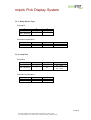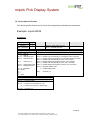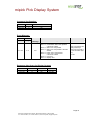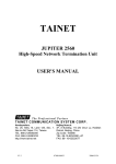
1
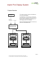
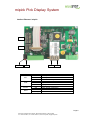
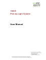
mipick
Pick-by-Light System
User Manual
microSYST Systemelectronic GmbH
Exclusive UK and Ireland Agent:
Metrix Electronics Ltd
tel: 0845 034 3234
www.metrix-electronics.com
microSYST Systemelectronic GmbH, Albert-Einstein-Straße 7, 92637 Weiden
Tel. +49 961 39166-0, Fax +49 961 39166-10, www.microsyst.de, [email protected]
mipick Pick Display System
Index
1
SYSTEM OVERVIEW
4
2
COMPONENTS
5
2.1
Distribution Unit
2.2
Distribution Unit for Ethernet TCP/IP
2.2.1 Distribution Unit for Profibus DP
2.3
3
4
5
Pick Displays
ASSEMBLY
5
5
8
12
14
3.1
Shaft Machining
3.1.1 Light Sensor (optional)
3.1.2 Shaft Termination / Clamp Module
14
14
15
3.2
Mounting the Shaft
15
3.3
Mounting the Distribution Unit
15
WIRING
16
4.1
Distribution Unit
17
4.2
Clamp Module
18
4.3
Pick Displays
18
4.4
Bus Termination Board
19
4.5
Light Sensor (optional)
19
ETHERNET
5.1
Configuration of the Ethernet Interface
5.2
Ethernet Communication
5.2.1 Transmit “Commands“
5.2.2 Receive “Status Messages”
20
20
22
23
24
Page 2
microSYST Systemelectronic GmbH, Albert-Einstein-Straße 7, 92637 Weiden
Tel. +49 961 39166-0, Fax +49 961 39166-10, www.microsyst.de, [email protected]
mipick Pick Display System
6
7
PROFIBUS DP
6.1
Configuration of the Profibus Interface
6.1.1 GSD File
6.1.2 Configuration Data
6.1.3 User Parameter Data
6.1.4 Diagnosis Data
25
25
25
26
26
6.2
DP Communication
6.2.1 Transmit “Commands”
6.2.2 Receive “Status Messages”
27
28
29
FRAME STRUCTURE
7.1
8
25
Structure of Commands
31
31
7.2
Structure of Status Messages
7.2.1 Command Confirmation
7.2.2 Event Message
7.2.3 Bus Member Message
31
31
31
32
7.3
General Frames
7.3.1 Show Address
7.3.2 Delete Display
7.3.3 Query Device Type
7.3.4 Lamp Test
7.3.5 Query Display Content
7.3.6 Query Software Version
33
33
33
34
34
35
35
7.4
36
Device-Specific Frames
VERSIONS OVERVIEW
38
Page 3
microSYST Systemelectronic GmbH, Albert-Einstein-Straße 7, 92637 Weiden
Tel. +49 961 39166-0, Fax +49 961 39166-10, www.microsyst.de, [email protected]
mipick Pick Display System
1 System Overview
The system basically consists of a distribution
unit an the pick displays.
Controller
Ethernet /
Profibus-DP
Profibus DP
230 VAC
The distribution unit serves as a converter between the system interface (Ethernet TCP/IP or
Profibus DP) and RS485 and provides the 12
VDC supply power for the displays.
There are two internal connections, that can operate up to 100 displays each.
Distribution Unit
RS485,
12 VDC
Line 1
Line 2
Clamp Module
Pickdisplay
Clamp Module
Pickdisplay
Pick Display
Pick Display
Pick Display
Pick Display
Bus Termination
Bus Termination
Page 4
microSYST Systemelectronic GmbH, Albert-Einstein-Straße 7, 92637 Weiden
Tel. +49 961 39166-0, Fax +49 961 39166-10, www.microsyst.de, [email protected]
mipick Pick Display System
2 Components
2.1 Distribution Unit
2.2 Distribution Unit for Ethernet TCP/IP
Power Supply
Interface
Ethernet/mipick
Circuit Breaker
230 VAC
Ethernet TCP/IP
mipick Displays
Line 2
mipick Displays
Line 1
Page 5
microSYST Systemelectronic GmbH, Albert-Einstein-Straße 7, 92637 Weiden
Tel. +49 961 39166-0, Fax +49 961 39166-10, www.microsyst.de, [email protected]
mipick Pick Display System
Inteface Ethernet / mipick
S1
S2
FAULT
RUN
LED
ACT
LINK
FAULT
RUN
LINK
Status
Green
Yellow
Off
Green
Yellow
Off
Red
Off
Green
Blinking
ACT
Meaning
Full-Duplex
Half-Duplex
No network activity
Physical network connection with 100 MBaud
Physical network connection with 10 MBaud
No physical network connection
No active TCP/IP connection
Active TCP/IP connection
No data traffic at the serial interface
Data traffic at the serial interface
Page 6
microSYST Systemelectronic GmbH, Albert-Einstein-Straße 7, 92637 Weiden
Tel. +49 961 39166-0, Fax +49 961 39166-10, www.microsyst.de, [email protected]
mipick Pick Display System
Positions marked with “■ ” are fixed and must not be changed!
Switch S1: Options
DIP
1
2
3
4
5
6
7
8
ON
Test mode:
All displays show their own RS485 address or the LED is switched on (if no
displays available). There should not be
Ethernet communication at the same time!
Use 128 RS485 addresses (0...127) for
the RS485 cycle,
enable the bus message C2
Send bus member messages (C1, C2)
automatically at a change (and after the
Ethernet connection has been established)
OFF
Normal mode
Use 64 RS485 addresses
(0...63) for the RS485 cycle,
bus message C2 locked
■
Send bus member messages
(C1, C2) only at a query (C0, C1
or C2)
■
■
■
■
Standard setting: DIP2, 4 = ON, remaining switches = OFF
Switch S2: RS485 Bus Termination
DIP
1
2
3
4
5
6
ON
■
■
■
Bus termination is set
Bus termination is set
OFF
■
No bus termination
No bus termination
Standard setting: DIP1 = OFF, remaining switches = ON
The bus termination must be set, if the interface is connected at the first position within the RS485 bus.
Page 7
microSYST Systemelectronic GmbH, Albert-Einstein-Straße 7, 92637 Weiden
Tel. +49 961 39166-0, Fax +49 961 39166-10, www.microsyst.de, [email protected]
mipick Pick Display System
2.2.1 Distribution Unit for Profibus DP
Power Supply
Circuit Breaker
Interface
Profibus/mipick
230 VAC
mipick Displays
Line 2
Profibus IN
mipick Displays
Line 1
Profibus OUT
Page 8
microSYST Systemelectronic GmbH, Albert-Einstein-Straße 7, 92637 Weiden
Tel. +49 961 39166-0, Fax +49 961 39166-10, www.microsyst.de, [email protected]
mipick Pick Display System
Interface Profibus / mipick
S2
S1
LED
red (FAULT)
green (RUN)
S3
Status
off
Meaning
Profibus DP connection established
no cyclical Profibus DP communication
on
or RAM error (if green LED is off)
no RS485 response (within the last 500 ms) or RS485
communication stopped, because a new status message is
blinking
existent and the former status message has not been confirmed (DP-OUT-QBS must be set to DP-IN-TBS)
off
Controller is not working (hardware error)
on
Controller is working
short off Profibus DP toggle byte was changed
(flickering) (command or status message transmitted)
Page 9
microSYST Systemelectronic GmbH, Albert-Einstein-Straße 7, 92637 Weiden
Tel. +49 961 39166-0, Fax +49 961 39166-10, www.microsyst.de, [email protected]
mipick Pick Display System
Positions marked with “■ ” are fixed and must not be changed!
Switch S1: RS485 Bus Termination
DIP
1
2
3
4
5
6
ON
■
■
■
Bus termination is set
Bus termination is set
OFF
■
No bus termination
No bus termination
Standard settings: DIP1 = OFF, remaining switches = ON
-> RS485 bus termination is set
Switch S2: DP Address, DP Bus Termination
DIP
1
2
3
4
5
6
7
8
9
10
Function
0
DP address Bit 2 (ON = 1)
1
DP address Bit 2 (ON = 2)
2
DP address Bit 2 (ON = 4)
3
DP address Bit 2 (ON = 8)
4
DP address Bit 2 (ON = 16)
5
DP address Bit 2 (ON = 32)
6
DP address Bit 2 (ON = 64)
reserved (= OFF ■)
both ON: Profibus bus termination set
both OFF: no Profibus bus termination
Only DP addresses 0...126 are allowed.
Standard settings: DIP1, 2 = ON, remaining switches = OFF
-> Profibus address = 3, no Profibus bus termination
Page 10
microSYST Systemelectronic GmbH, Albert-Einstein-Straße 7, 92637 Weiden
Tel. +49 961 39166-0, Fax +49 961 39166-10, www.microsyst.de, [email protected]
mipick Pick Display System
Switch S3: Options
DIP
1
2
3
4
5
6
7
8
ON
Test mode:
All displays show their own RS485 address or the LED is switched on (if no
displays available). There should not be
Profibus communication at the same time!
Use 128 RS485 addresses (0...127) for
the RS485 cycle,
enable the bus message C2
Transmit every status message immediately (separately) to the DP master (-> easier handling but slower)
Send bus member messages (C1, C2)
automatically at a change (and after
power-up and every restart of DP communication
OFF
Normal mode
Use 64 RS485 addresses
(0...63) for the RS485 cycle,
bus message C2 locked
Accumulate status messages
until DP-IN buffer is full or the
current polling cycle is finished.
Send bus member messages
(C1, C2) only at a query (C0, C1
or C2)
■
■
■
■
Standard setting: DIP2, 4 = ON, remaining switches = OFF
Page 11
microSYST Systemelectronic GmbH, Albert-Einstein-Straße 7, 92637 Weiden
Tel. +49 961 39166-0, Fax +49 961 39166-10, www.microsyst.de, [email protected]
mipick Pick Display System
2.3 Pick Displays
Technical Data
Display type:
Character height:
Digits:
Display colour:
Operating voltage:
Current consumption:
Display:
Addresses:
Safety push button:
Signal lamp:
Housing:
Shaft depth:
Housing colour:
Mounting:
Protection:
Operating temp.:
Storage temp.:
7 segment LED
29 mm
on request
red, green and on request
10 to 12 VDC, depending on variant
up to max 360 mA, depending on variant
LED, 0 to 9, ASCII character set + special characters
0 to 99
metal design
mechanical service life: 1,000,000 cycles
diameter: 12 mm
individually replaceable
LED (red, green)
LED diameter: 10 mm
Metal mount
Individually replaceable
aluminium, anodized
30 mm
natural or coloured, anodized
snap-on mounting
front panel up to IP54
0 to 50 °C
-25 to +70 °C
Example:
Page 12
microSYST Systemelectronic GmbH, Albert-Einstein-Straße 7, 92637 Weiden
Tel. +49 961 39166-0, Fax +49 961 39166-10, www.microsyst.de, [email protected]
mipick Pick Display System
Address Setting
All pick displays of a line must have an explicit address. For this, a DIP switch at
the backside is used.
Switch
DIP 1
DIP 2
DIP 3
DIP 4
DIP 5
DIP 6
DIP 7
DIP 8
Address
0
2
1
2
2
2
3
2
4
2
5
2
6
2
-
OFF
0
0
0
0
0
0
0
-
ON
1D
2D
4D
8D
16D
32D
64D
-
Please see labeling of the DIP switch for the ON / OFF position.
Page 13
microSYST Systemelectronic GmbH, Albert-Einstein-Straße 7, 92637 Weiden
Tel. +49 961 39166-0, Fax +49 961 39166-10, www.microsyst.de, [email protected]
mipick Pick Display System
3 Assembly
3.1 Shaft Machining
The following machining must be done before the mounting of the shaft:
3.1.1 Light Sensor (optional)
Machining:
shaft cover
slot
shaft bottom
Mounting:
The holder is mounted with two screws or rivets (if possible).
Page 14
microSYST Systemelectronic GmbH, Albert-Einstein-Straße 7, 92637 Weiden
Tel. +49 961 39166-0, Fax +49 961 39166-10, www.microsyst.de, [email protected]
mipick Pick Display System
3.1.2 Shaft Termination / Clamp Module
Every shaft is terminated. For this, covers with and without cable entries are available:
Covers with cable entry have four screw sockets for the mounting of the clamp module.
The clamp module splits the incoming cable to a flat ribbon cable and single conductors. Depending on the locality, it can be necessary to insert a second clamp module at
the shaft end which bundles the conductors again in order to get to the next shaft.
Hole pattern:
slot
shaft bottom
3.2 Mounting the Shaft
The mounting of the display shaft happens with holes in the shaft bottom. Please
use enough fixing points for adequate stability.
3.3 Mounting the Distribution Unit
The distribution unit is mounted with 4 screws M8 via holes in the housing bottom.
Page 15
microSYST Systemelectronic GmbH, Albert-Einstein-Straße 7, 92637 Weiden
Tel. +49 961 39166-0, Fax +49 961 39166-10, www.microsyst.de, [email protected]
mipick Pick Display System
4 Wiring
Page 16
microSYST Systemelectronic GmbH, Albert-Einstein-Straße 7, 92637 Weiden
Tel. +49 961 39166-0, Fax +49 961 39166-10, www.microsyst.de, [email protected]
mipick Pick Display System
4.1 Distribution Unit
Supply Power (230 VAC)
System Interface
Ethernet:
Profibus DP
IN
OUT
Display Interface
Supply power and RS485 bus for both display lines
Line 2
Line 1
to the clamp module(s)
Page 17
microSYST Systemelectronic GmbH, Albert-Einstein-Straße 7, 92637 Weiden
Tel. +49 961 39166-0, Fax +49 961 39166-10, www.microsyst.de, [email protected]
mipick Pick Display System
4.2 Clamp Module
The connections V+ and GND of the distribution unit are connected to the +VIN and GND
terminals of the clamp module.
RX/TX+ and RX/TX- of the distribution unit are connected to the RX/TX+ und RX/TX- terminals of the clamp module.
From here we continue with a 10-pole flat ribbon cable for the RS485 and single conductors for the supply power of the displays:
from distribution unit
to the displays
4.3 Pick Displays
Power connection via
squeeze connectors
Connector for the
light sensor
(depending on
display type)
RS485 connection
via flat ribbon
cable
Page 18
microSYST Systemelectronic GmbH, Albert-Einstein-Straße 7, 92637 Weiden
Tel. +49 961 39166-0, Fax +49 961 39166-10, www.microsyst.de, [email protected]
mipick Pick Display System
4.4 Bus Termination Board
The last pick display of a line is equipped with a bus termination board. This board is
plugged at its free RS485 connection (10-pole flat ribbon connector):
4.5 Light Sensor (optional)
The power is taken from the continuous strand via squeeze connectors (like the pick
displays).
The signal line of the sensor is connected to the related pick display.
Page 19
microSYST Systemelectronic GmbH, Albert-Einstein-Straße 7, 92637 Weiden
Tel. +49 961 39166-0, Fax +49 961 39166-10, www.microsyst.de, [email protected]
mipick Pick Display System
5 Ethernet
5.1 Configuration of the Ethernet Interface
The distribution unit is preset with the following network settings:
IP address:
Net mask:
Port:
192.168.4.200
255.255.255.0
10001
To change these parameters, proceed as follows:
Advice for Windows 7 users:
The Telnet client must be activated:
Start -> Control Panel -> Programs -> Turn Windows features on or off
-> Telnet Client
• Switch on the supply power and connect the distribution unit to the network hub
with an RJ45 cable (1:1 cable) or directly to a PC (crosslink cable).
• Start the “MS DOS entry prompt” at your Windows PC.
With Windows 7 you must have extended rights:
Start -> All Programs -> Accessories -> double-click at Command Promp -> Run
as Administrator
• Enter the desired IP address for the device to the ARP table:
ARP -S XXX.XXX.XXX.XXX xx-xx-xx-xx-xx-xx <CR>
XXX.XXX.XXX.XXX
xx-xx-xx-xx-xx-xx
: desired IP address
: Ethernet MAC address of the interface
(see label at the housing)
Page 20
microSYST Systemelectronic GmbH, Albert-Einstein-Straße 7, 92637 Weiden
Tel. +49 961 39166-0, Fax +49 961 39166-10, www.microsyst.de, [email protected]
mipick Pick Display System
• Establish a Telnet connection to port 1:
TELNET XXX.XXX.XXX.XXX 1 <CR>
This connection will fail (disconnect within 3 seconds). However, the IP address
of the interface is temporarily changed.
Close the Telnet window after acknowledging the error message.
• Establish a Telnet connection to port 9999:
TELNET XXX.XXX.XXX.XXX 9999 <CR>
After the connection has been established, immediately press the enter key
(within 5 seconds) in order to enter the setup mode.
• Please do never select “7” (Defaults). Those settings do not match for the
system.
• Enter “0” (Server).
• Enter the desired IP address and press the enter key.
• Repeatedly press the enter key until
”Netmask: Number of Bits for Host Part (…)“ appears.
Enter here the number of free bits for the IP address,
f.e. “8“ for the netmask 255.255.255.0
(=11111111.11111111.11111111.00000000) or
“11“ for the netmask 255.255.248.0
(=11111111.11111111.11111000.00000000) and press the enter key.
• Repeatedly press the enter key until “Your choice?” appears.
• Press “9” to save all settings (-> the Telnet connection is interrupted).
Configuration of the Ethernet interface is now complete.
Now, the control frame can be transmitted via the selected IP address (TCP/IP connection via port 10001).
Page 21
microSYST Systemelectronic GmbH, Albert-Einstein-Straße 7, 92637 Weiden
Tel. +49 961 39166-0, Fax +49 961 39166-10, www.microsyst.de, [email protected]
mipick Pick Display System
5.2 Ethernet Communication
The Ethernet interface of the distribution unit serves for the communication between a
controller (for example PC or PLC) and the mipick devices.
“Commands” are sent from the controller to the interface via Ethernet and then forwarded to the particular mipick devices.
“Status messages” are sent from the mipick devices to the interface via RS485 and
then forwarded to the controller via Ethernet.
The Ethernet interface acts as bus master at RS485 side.
As long as no “commands” are available, the bus-sharing units (mipick devices) are
polled cyclically (order: address 0 to 63, 0 to 63, … or 0 to 127, 0 to 127,…). If there
happens an event at this (for example “button was pressed”), the mipick replies with a
corresponding frame and then a related “status message” is sent via Ethernet.
If there is a “command” available for a certain RS485 address, it is sent to the bussharing unit instead of the polling frame. The response of the mipick device is acknowledged via the Ethernet.
If there is identified that a new bus-sharing unit was added or a former existing bus sharing unit does not respond (correctly), a special frame is received via the Ethernet. The
controller can explicitly request this “bus member message” in order to get the current
bus status.
“Commands” and “status messages” are described (generally and in combination with
the relating display) in the following chapters. They have the following structure:
A
Address of RS485 device
1 Byte
L
Length of the data
1 Byte
D
Data
1...20 Bytes
Page 22
microSYST Systemelectronic GmbH, Albert-Einstein-Straße 7, 92637 Weiden
Tel. +49 961 39166-0, Fax +49 961 39166-10, www.microsyst.de, [email protected]
mipick Pick Display System
5.2.1 Transmit “Commands“
The transmission of the “commands” happens from the controller to the Ethernet interface and then via a RS485 bus to the concerning mipick devices.
With every TCP/IP frame, one ore several commands (without gap) are transmitted to
the Ethernet interface. Every command has the structure “address”, “length”, “data”.
A new command must only then be sent to a certain address, if the last command has
been answered or at least approximately 1 second has elapsed. Then, the bus member
has not answered or not answered correctly.
After a “broadcast command” you have to wait for the command confirmations first (one
per existing bus member) before you send a new command. 1 second is enough.
Please note: If you wait for several command confirmations, they must not necessarily
arrive in the same order like the corresponding commands have been sent. It’s possible
that an “event message” or “bus member message” intervenes between the single
command confirmation frames!
Example:
The value „12“ shall be shown at display (mipick R324) with address 4:
Send command via TCP/IP (in hexadecimal presentation):
04 05 33 31 32 00 00
(address = 4, length = 5 bytes, data = 33 31 32 00 00)
Page 23
microSYST Systemelectronic GmbH, Albert-Einstein-Straße 7, 92637 Weiden
Tel. +49 961 39166-0, Fax +49 961 39166-10, www.microsyst.de, [email protected]
mipick Pick Display System
5.2.2 Receive “Status Messages”
There are three types of status messages:
1. Command confirmation (= command response)
2. Event messages (for example “button was pressed“)
3. Bus member message (“device removed or added”)
Status messages are sent to the controller with a TCP/IP frame. Every TCP/IP frame
can contain one or more status messages (without gap). Every status message has the
structure “address”, “length”, “data”.
Examples:
a) Command confirmation to the command above:
Receive the status message “command confirmation” via TCP/IP (in HEX representation):
04 01 33
(address = 4, length = 1, data = 33)
b) Button of display 4 was pressed short:
Receive the status message “event message“ via TCP/IP (in HEX representation):
04 03 00 01 0C
(address = 4, length = 3, data = 00 01 0C)
Note: Only one status message is transferred in the examples above but if there are several status messages, they are received simultaneously.
Page 24
microSYST Systemelectronic GmbH, Albert-Einstein-Straße 7, 92637 Weiden
Tel. +49 961 39166-0, Fax +49 961 39166-10, www.microsyst.de, [email protected]
mipick Pick Display System
6 Profibus DP
6.1 Configuration of the Profibus Interface
6.1.1 GSD File
The device database file „micr05D0“, which is part of the delivery, is used for the integration of the Profibus DP interface (DP slave) to the Profibus. Among other
things, it contains the necessary identifiers for the configuration of the input- output
data widths (see next chapters).
6.1.2 Configuration Data
With the configuration, the user has the possibility to set an individual data width of
the cyclic data exchange. Therefore, the following identifiers (max. 30) must be selected in any desired order.
The DP master transmits the identifier to the DP slave before it starts the cyclic data
exchange.
Byte no.
x
x
x
x
x
x
x
x
x
Data identifier
0x10
0x11
:
0x1F
Number of bytes
1
2
:
16
0x20
0x21
:
0x2F
1
2
:
16
0x30
0x31
:
0x3F
1/1
2/2
:
16/16
Function / Description
Input Data
Input Data
Input Data
Output Data
Output Data
Output Data
Input-/Output Data (1 byte each)
Input-/Output Data (2 bytes each)
Input-/Output Data (16 bytes each)
The minimum number of input or output bytes is 6 bytes each.
The maximum number of input or output bytes is 200 bytes each, but an overall
length of 300 bytes (input + output) must not be exceeded.
Standard configuration: 0x3F, 16 input-/ output bytes.
Page 25
microSYST Systemelectronic GmbH, Albert-Einstein-Straße 7, 92637 Weiden
Tel. +49 961 39166-0, Fax +49 961 39166-10, www.microsyst.de, [email protected]
mipick Pick Display System
6.1.3 User Parameter Data
User parameter data are not utilized by the interface. However, a test is run to determine whether or not the Profibus master transfers user parameter data. If user
parameter data are transferred, Profibus initialization is disabled and the slave’s parameters must be reconfigured.
Note:
Standard parameters configuration is required and is normally installed by the utilized DP configurators.
6.1.4 Diagnosis Data
The interface does not support any extended diagnosis data. Default diagnosis is
utilized.
Page 26
microSYST Systemelectronic GmbH, Albert-Einstein-Straße 7, 92637 Weiden
Tel. +49 961 39166-0, Fax +49 961 39166-10, www.microsyst.de, [email protected]
mipick Pick Display System
6.2 DP Communication
The DP master handles the Profibus interface (DP slave) as a standard I/O device. This
means, there are DP output data, which are cyclically transmitted to the slave and DP
input data, which are cyclically received from the slave.
The structure of those I/O data is like follows:
DP-OUT:
TBK
QBS
LBK
A L D
A L D
…
A L D
Commands
DP-IN:
QBK
TBS
LBS
A L D
A L D
…
A L D
Status Messages
TBK:
QBK:
LBK:
Toggle byte for the commands
Confirmation byte for the commands (= TBK after data adoption)
Length byte for the commands
TBS:
QBS:
LBS:
Toggle byte for the status messages
Confirmation byte for the status messages (= TBS after data adoption)
Length byte for the status messages
A:
L:
D:
Address of the RS485 bus sharing unit (pick display)
Length of the data
Data (max. 20 bytes)
Notes:
After the (new) start of the Profibus DP communication, all DP OUT bytes and all DP IN
bytes have the value 0.
With the help of the configuration, the number of DP IN bytes and DP OUT bytes must
be chosen leastwise as large, that the largest possible command or the largest possible
status message has enough space. The maximum I/O width must not be exceeded (see
chapter „configuration data“).
Page 27
microSYST Systemelectronic GmbH, Albert-Einstein-Straße 7, 92637 Weiden
Tel. +49 961 39166-0, Fax +49 961 39166-10, www.microsyst.de, [email protected]
mipick Pick Display System
6.2.1 Transmit “Commands”
The „commands“ specify, what shall be shown at the displays or how they shall behave.
The transmission of the commands happens from the DP master to the Profibus interface (DP slave) and from here via the RS485 bus to the respective displays.
Procedure:
1. In the DP OUT area „commands“, you must enter the command or even several
commands (without gap). Every command consists of „address“, „length“ and „data“.
2. The length of all command bytes must be entered at „LBK“.
3. Finally, „TBK“ is increased by one value.
4. Now, the DP slave starts to evaluate the commands and forward it to the corresponding displays. After this procedure is finished, the „QBK“ is set to the value of
the previous changed „TBK“.
5. If there are further commands, you can continue with point 1.
Example:
The value „12“ shall be shown at display 4 (mipick R324):
1. Input the command:
DP-OUT(hex) = 00 XX 00 04 05 33 31 32 00 00
2. Set „LBK“:
DP-OUT(hex) = 00 XX 07 04 05 33 31 32 00 00
3. Increase „TBK“:
DP-OUT(hex) = 01 XX 07 04 05 33 31 32 00 00
4. Wait for „QBK“:
DP-IN(hex) = 00 XX XX XX ...
->
DP-IN(hex) = 01 XX XX XX ...
Page 28
microSYST Systemelectronic GmbH, Albert-Einstein-Straße 7, 92637 Weiden
Tel. +49 961 39166-0, Fax +49 961 39166-10, www.microsyst.de, [email protected]
mipick Pick Display System
6.2.2 Receive “Status Messages”
There are three types of „status messages“:
4. Command confirmations (= command response)
5. Event messages (for example „button has been pressed“)
6. Bus member messages („device has been removed/added“)
The status messages must be fetched from the DP master as fast as possible, otherwise the RS485 communication with the displays can slow down or even stop (until the
status messages are fetched)!!!
Procedure:
1. If the „TBS“ changes, there are status messages available for pickup.
2. Now, the status messages to be fetched are available in the DP IN area „status
messages“ (without gap, overall „LBS“ bytes). Every status message consists of
„address“, „length“ and „data“.
3. After the status messages have been read out, the DP master must set the „QBS“ to
the value of „TBS“. This should happen as fast as possible (in order not to slow
down the RS485 communication).
4. Continue with point 1.
Examples:
a) Command confirmations to the command above:
1. „TBS“ changes:
DP-IN(hex) = XX 00 XX XX XX ...
->
DP-IN(hex) = XX 01 03 04 01 33
2. Read out the status message:
“LBS” = 3
„Address“ = 4
„Length“ = 1
„Data“ = 33H (command confirmation)
3. Set „QBS” to the value of “TBS”:
DP-OUT(hex) = XX 01 XX XX XX …
Page 29
microSYST Systemelectronic GmbH, Albert-Einstein-Straße 7, 92637 Weiden
Tel. +49 961 39166-0, Fax +49 961 39166-10, www.microsyst.de, [email protected]
mipick Pick Display System
b) Button of display 4 was pressed short:
1. „TBS“ changes:
DP-IN(hex) = XX 01 XX XX XX …
->
DP-IN(hex) = XX 02 05 04 03 00 01 0C
2. Read out the status message:
“LBS” = 5
„Address“ = 4
„Length“ = 3
„Data“ = 00H 01H 0CH (event message: button pressed short, display value = „12“)
3. Set „QBS” to the value of “TBS”:
DP-OUT(hex) = XX 02 XX XX XX …
Note:
In the examples above, only one status message is transmitted at once.
If there are more status messages available, they are transmitted at the same time in
order to utilize the available DP IN bytes as far as possible and accelerate the communication.
If DIP switch S3-3 is in ON position, every status message is reported separately (to
simplify the evaluation at the DP master side).
Page 30
microSYST Systemelectronic GmbH, Albert-Einstein-Straße 7, 92637 Weiden
Tel. +49 961 39166-0, Fax +49 961 39166-10, www.microsyst.de, [email protected]
mipick Pick Display System
7 Frame Structure
7.1 Structure of Commands
►
Address
Length
Command
0 to 127,
255*
Number of
following bytes
for example 33H
= “control display”
1
th
Data
Parameter
... Parameter
n
th
Parameter
*Address = 255: broadcast command:
This command is sent to all possible bus addresses (0...63 or 0...127). Only the really
existing MIPICKS of the bus, which are supported by the command, evaluate it and respond with a “command confirmation”.
7.2 Structure of Status Messages
7.2.1 Command Confirmation
◄
Address
0 to 127
Length
>= 1
Data
Command confirmation
Possible response data
for example 33H
Every command is receipted with a command confirmation. With this, the complete
communication cycle from the controller to the MIPICKS and back again is guaranteed.
If necessary, response data from the MIPICK is forwarded.
7.2.2 Event Message
◄
Address
Length
0 to 127
Number of
following
bytes
Event
message
00 H
Status byte
Contains (bitcoded) information
to the event, that
happened
1
th
Data
Parameter
... Parameter
n
th
Parameter
Additional event information
(if the status byte is not enough)
All existing MIPICKs of the RS485 bus (addresses 0 to 63 or 0 to 127) are always
polled. If the “status byte” in unequal to 0 OR at least an additional “parameter byte” is
received, an event is available. It is forwarded from the interface to the controller then.
Page 31
microSYST Systemelectronic GmbH, Albert-Einstein-Straße 7, 92637 Weiden
Tel. +49 961 39166-0, Fax +49 961 39166-10, www.microsyst.de, [email protected]
mipick Pick Display System
7.2.3 Bus Member Message
Data
◄
Address
Length
255
(comes
directly
from the
interface)
9
Bus Member
Message
C1H
(bus addresses 0
to 63)
C2H
(bus addresses
64 to 127,
only if 128 addresses are set
with DIP switch)
BTN0
Bus member states of
the addresses 0 to 7 or
64 to 71:
BTN...
BTN7
...
Bus member states of the
addresses 56 to 63 or 120
to 127:
(bit 0 to 7)
1 = device available,
0 = device not available
(bit 0 to 7):
1 = device available,
0 = device not available
The bus member messages can be requested by transmitting the following „interface
commands“:
►
Address
Length
255
(directly
to the
interface)
1
Data
„Interface Command“
C1H :
Request bus member message C1H
C2H :
Request bus member message C2H (if 128 addresses)
C0H :
Request bus member messages C1H and C2H (if 128 addresses)
If the corresponding DIP switch is in position „ON“, the bus member messages are sent
automatically ...
•
after every change (new bus member identified or not available anymore)
•
every restart of the communication = establishing the Profibus connection
(after completion of the currently running polling cycle).
Page 32
microSYST Systemelectronic GmbH, Albert-Einstein-Straße 7, 92637 Weiden
Tel. +49 961 39166-0, Fax +49 961 39166-10, www.microsyst.de, [email protected]
mipick Pick Display System
7.3 General Frames
The following frames proceed basic functions and are supported by most displays.
7.3.1 Show Address
Command:
1
Address
0 to 127,
255 = Broadcast
2
Length
3
Command
1
01H
2
Length
1
3
Command
01H
2
Length
3
Command
1
02H
2
Length
1
3
Command
02H
Command confirmation:
1
Address
0 to 127
7.3.2 Delete Display
Command:
1
Address
0 to 127,
255 = Broadcast
Command confirmation:
1
Address
0 to 127
Page 33
microSYST Systemelectronic GmbH, Albert-Einstein-Straße 7, 92637 Weiden
Tel. +49 961 39166-0, Fax +49 961 39166-10, www.microsyst.de, [email protected]
mipick Pick Display System
7.3.3 Query Device Type
Command:
1
Address
0 to 127,
255 = Broadcast
2
Length
3
Command
1
03H
2
Length
2
3
Command
03H
4
Device type
= command byte
1
Address
2
Length
3
Command
0 to 127,
255 = Broadcast
2
04H
4
Lamp text
01H = start
2
Length
1
3
Command
04H
Command confirmation:
1
Address
0 to 127
7.3.4 Lamp Test
Command:
00H = stop
Command confirmation:
1
Address
0 to 127
Page 34
microSYST Systemelectronic GmbH, Albert-Einstein-Straße 7, 92637 Weiden
Tel. +49 961 39166-0, Fax +49 961 39166-10, www.microsyst.de, [email protected]
mipick Pick Display System
7.3.5 Query Display Content
Command:
1
Address
0 to 127,
255 = Broadcast
2
Length
3
Command
1
05H
Command confirmation:
1
Address
2
Length
3
Command
0 to 127
X
05H
4
Digit 1
ASCII code
or
real value (then, from MSB
to LSB if valuation > 255)
...
...
„
Note:
The number of display and the visualisation (ASCII or binary) can vary depending display type.
7.3.6 Query Software Version
Command:
1
Address
0 to 127,
255 = Broadcast
2
Length
3
Command
1
06H
Command confirmation:
1
Address
0…127
2
Length
13
Data
Command
06H
‘H’
‘L’
ASCII code
‘-’
‘V’
ASCII code
Data
ASCII code
ASCII code
ASCII code
Data
‘.’
ASCII code
ASCII code
Page 35
microSYST Systemelectronic GmbH, Albert-Einstein-Straße 7, 92637 Weiden
Tel. +49 961 39166-0, Fax +49 961 39166-10, www.microsyst.de, [email protected]
mipick Pick Display System
7.4 Device-Specific Frames
The device-specific frames can be found in the separately enclosed frame description.
Example: mipick R225
Command:
1
Address
0 to 127
255 = Broadcast
2
Length
3
Command
6
49H
Bit 0=0:
=1:
Bit 1=1:
Bit 2=1:
6
Options 1
LED on
LED off
LED blinks slow
LED blinks fast
Bit 3:
reserved (=0)
Bit 4=1: Display blinks slow
Bit 5=1: Display blinks fast
Bit 7, 6: Brightness:
00 = bright
01 = :
10 = :
11 = dark
4
Digit 1
Bit 0 to 6: ASCII code 30 to 39H
Bit 7=1: Decimal point ON
5
Digit 2
’’
7
Options 2
Bit 0=1:
Bit 1=1:
Bit 2=1:
Bit 3=1:
Bit 4=1:
Bit 5=1:
Disable LED automatically, if confirmation button is pressed
Disable display automatically, if confirmation button is pressed
Disable LED automatically, if button “Ø“ is pressed
Disable display automatically if button “Ø“ is pressed
Disable LED automatically, if button “INV“ is pressed
Disable display automatically, if button “INV“ is pressed
Bit 6=0: Suppress leading zeros
=1: Enable leading zeros
Bit 7:
reserved (=0)
8
Optionen 3
Bit 0=1: +/- buttons locked
Bit 1=1: +/- buttons count unlimited (0…99)
=0: +/- buttons count from 0 to preset value
Bit 2 to 7: reserved (=0)
Page 36
microSYST Systemelectronic GmbH, Albert-Einstein-Straße 7, 92637 Weiden
Tel. +49 961 39166-0, Fax +49 961 39166-10, www.microsyst.de, [email protected]
mipick Pick Display System
Command Confirmation:
1
Address
0 to 127
2
Length
1
3
Command
49H
Event Message:
1
2
Address
Length
0 to 127
3
Event
Message
2/3
00 H
4
5
Status byte
Value
Bit 0=1: Confirmation button was pressed
Bit 1=1: Confirmation button was pressed
2 seconds at least
Bit 2=1: Button “Ø“ was pressed
Bit 3=1: Button “Ø“ was pressed 2 seconds
at least
Bit 4=1: button “INV“ was pressed
Bit 5=1: button “INV“ was pressed
2 seconds at least
Bit 6=1: LED error
Bit 7=1: Display error
Only if any button has
been pressed (at
least one of the bits 0
to 5 of the status byte
= 1)
0 to 99
Response after Query the Display Content:
1
Address
0 to 127
2
Length
2
3
Command
05H
4
Value
0 to 99
Page 37
microSYST Systemelectronic GmbH, Albert-Einstein-Straße 7, 92637 Weiden
Tel. +49 961 39166-0, Fax +49 961 39166-10, www.microsyst.de, [email protected]
mipick Pick Display System
8 Versions Overview
Version
1.00
1.10
1.20
1.30
1.30m
Date
Remarks, Descriptions
03.08.09
17.01.11
08.02.11
31.03.14
04.08.14
Document created (German language)
Document translated
Chapter “Device-Specific Frames” changed (R225)
Interface (Ethernet, Profibus) changed
Metrix links added
Certified per DIN EN ISO 9001.
microSYST Systemelectronic GmbH
Exclusive UK and Ireland Agent:
Metrix Electronics Ltd
tel: 0845 034 3234
www.metrix-electronics.com
Page 38
microSYST Systemelectronic GmbH, Albert-Einstein-Straße 7, 92637 Weiden
Tel. +49 961 39166-0, Fax +49 961 39166-10, www.microsyst.de, [email protected]