1
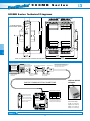
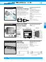
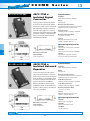
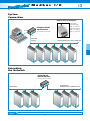
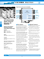
900MB
Modbus/RS-485
Series
High-Density Discrete I/O Module
Inputs (4)
Twelve
Discrete
Inputs or Outputs
or
Outputs (4)
Inputs (4)
or
Outputs (4)
Isolation
RS-485
Inputs (4)
Modbus
or
BusWorks® Modbus I/O
Outputs (4)
901/902/903MB
Multi-Channel
Discrete I/O
Modules
Active-Low Inputs
Sinking Outputs
(Low-Side Switching)
Models
901MB: 12 input channels
902MB: 12 output channels
903MB: 12 input/output channels
Input
Twelve input channels (901, 903 models only)
0 to 35V DC
Output
Twelve output channels (902, 903 models only)
O to 35V DC
Network Communication
Modbus-RTU high-speed RS-485
Power Requirement
10 to 36V DC,
24V AC
Approvals
CE marked. UL, cUL listed
Class I; Division 2; Groups A, B, C, D.
10-36V DC
or 24V AC
Power
■ Description
■ Special Features
These modules provide twelve discrete input
and/or output channels. Isolation separates the
I/O, power, and network circuits. Network
communication adheres to the industry-standard
RS-485 Modbus RTU protocol. Both AC and DC
power sources are supported with wide range,
nonpolarized, diode-coupled terminals.
■
Standard Modbus RTU protocol with high-speed
RS-485 communication (up to 115K bps)
■
Twelve I/O channels in a single inch-wide unit
reduces system costs and saves panel space
■
High-voltage, high-current, open-drain outputs
enable direct (low-side) control of external
devices
■
High-voltage buffered inputs monitor discrete
levels from a variety of industrial devices
■
Tandem input/output circuitry (903 models
only) connects input buffers with open-drain
outputs for convenient loopback monitoring of
the output state
■
Outputs have built-in over-temperature and
over-current shut-down protection, plus active
clamping circuits for switching inductive loads
■
Watchdog timers provide a configurable
failsafe output state for use when host
I/O communication is lost
■
Three-way isolation eliminates potential
ground loops between power, I/O, and
network circuitry
■
Self-diagnostics monitor microcontroller activity
to detect operational failures (lock-up) and
execute a reset to restore communication
The open-drain outputs are intended for currentsinking or low-side switching applications. The
buffered inputs are active-low. These models are
the complement of the 904, 905, and 906 units
which have open-source, high-side output
switches and active-high inputs. Socketed pull-up
resistors are easily removed or exchanged to satisfy your application requirements.
The 903MB model has twelve input/output
points that may be used as inputs or outputs on
a bit-by-bit basis. Outputs may be read back to
verify output settings.
Combining flexible I/O types, wide I/O ranges,
and a network interface in a single package,
makes this instrument extremely powerful.
Multi-channel design adds cost-efficiency and
allows high-density mounting. Plus, safe, rugged
construction makes these modules reliable for
use in both control room and distributed field I/O
applications. Custom module configurations are
also possible (consult factory for details).
Tel: 248-624-1541 Fax: 248-624-9234 e-mail: [email protected] www.acromag.com
24
Modbus
I/O
■ Performance
■
Discrete Inputs
(901 & 903 models only)
Input Type
5.6K ohm pull-up resistor SIPs are installed in sockets
at each port (four-channels per port).
General
I/O Pull-ups and Socket
■
12 active-low, buffered inputs, with a common connection. Inputs include transient suppression devices
and series connected 100K ohm resistors, plus diode
over-voltage clamps to the internal +5V supply.
Input Signal Voltage Range
0 to 35V DC, maximum.
Input Current
293µA, typical at 35V DC.
Input Signal Threshold
Input Resistance
100K ohms, typical.
External excitation voltage for each four-channel port
is limited to 35V or less.
Supported Modbus Commands
The command/response protocol for communicating
with this module adheres to the Modbus/RTU standard
for the following Modbus Functions.
Read Coil (Output) Status
Read Input Status
Read Holding Registers
Force Single Coil (Output)
Preset Single Register
Reset Slave
Force Multiple Coils (Outputs)
Preset Multiple Registers
Report Slave ID
LED Indicators
Input Hysteresis
LEDs indicate power, status, and discrete level.
100mV DC, typical.
Power Requirements
Discrete Outputs
(902 & 903 models only)
Output Type
10 to 36V DC,
22 to 26V AC.
12 independent, open-drain, DMOS MOSFET switches
with a common source connection that operate as
low-side switches.
Supply
10V DC
24V DC
24V AC
■
Supply Current
Output Voltage Range
0 to 35V DC max. (0 to 500mA/channel continuous).
External voltage source required.
Output ON Resistance
0.28 ohms maximum.
Models
901MB-0900
Discrete input module
902MB-0900
Discrete output module
903MB-0900
Discrete input/output module
Accessories
900C-SIP
Configuration Software Interface Package
(includes software CD-ROM for Windows, RS-232/485
converter, and RS-485/three-wire cable)
5034-225
USB-to-RS232 adapter. See page 41 for more info.
TBK-B02
Optional terminal block kit, barrier strip style, 4 pcs.
TBK-S02
Optional terminal block kit, spring clamp style, 4 pcs.
PS5R-D24
Power supply (24V DC, 2.1A).
See Power Supplies on page 183.
For more information on software, network hardware,
and mounting accessories, please see Pages 39-41.
Current Draw
80mA maximum
40mA maximum
70mA rms maximum
Isolation
1500V AC for 60 seconds or 250V AC continuous.
3-way isolation between I/O, network, and power
circuits.
Output Response Time
Optional terminal blocks: barrier strip (left) and
spring clamp (right). Cage clamp terminal is standard.
Force Single Coil: Output updates within 250µs of
receipt of a command.
Force Multiple Coils: First coil updates in 250µs,
followed successively by additional coils every 180µs.
DIGITAL INPUT CONNECTIONS (ACTIVE LOW)
DIGITAL OUTPUT CONNECTIONS
5V TTL LOGIC - INPUT CAN BE PULLED
UP INTERNALLY OR EXTERNALLY
CH 3
RTN
CH 6
CH 7
RTN
CH 2
D
D
B
A
TB3
CH 0
CH 1
COM
INTERNAL INPUT
PULL-UPS ARE OPEN
CH 3
100K
TO OTHER 3
CHAN OF PORT
V
DIGITAL
I/O
I/O
5-35V
902MB/903MB
ON
OFF
NETWORK
COMMUNICATION
TB3
EXC1
EXC3
COM
TB2
TB1
CH 5
PWR
RTN
CH 4
CH 8
TB4
RS485
DIGITAL
I/O
EXC2
DIGITAL IN or OUT
21 22 23 24 25 26
DUP
CH 9
903MB shown.
901MB & 902MB
are similar.
TB2
SPST
RELAY
CH10
36 35 34 33 32 31
+ 12-24V DC,
TYPICAL
RTN
CH 2
TB1
RTN
CH 1
RTN
CH11
TB4
EXC
DIGITAL
I/O
CH 0
46 45 44 43 42 41
INP
EXC1
DIGITAL IN or OUT
TB1
DIGITAL IN or OUT
EXC
11 12 13 14 15 16
RTN
DIGITAL I/O
SHARES
RETURN
LOAD
+5V
INP
INP
EXC
903MB
+5V
RTN
AC/DC
POWER
10 TO 36V DC
OR 24V AC
NON-POLARIZED
TB1
EXC1
OUT
CH 0
DIGITAL I/O
SHARES
RETURN
RTN
CH 1
CH 2
CH 3
RTN
RTN
Tel: 248-624-1541 Fax: 248-624-9234 e-mail: [email protected] www.acromag.com
25
BusWorks® Modbus I/O
TTL compatible with 100mV of hysteresis, typical.
Low-to-High threshold is 1.7VDC, High-to-Low is
1.6VDC, typical. Limited to TTL levels of 0.8VDC
(max. LOW level) and 2.0VDC (min. HIGH level).
Excitation (per port)
■ Ordering
Information
Modbus
■ Accessories
Configuration Tools
Acromag provides a full set of tools to help you
get your modules set up and ready to install.
■
Software Interface Package
See Page 39 for more information.
Includes the following:
- Configuration Software Utility
- Instruction manuals
- Serial port converter
- Interface cable
Universal 50W Power Supply (Page 39)
Isolated RS-232/485 Converter (Page 40)
Isolated RS-485 Network Repeater (Page 40)
■ General Module
Specifications
Communication Interface
Network Communication
■
Modbus-RTU protocol, RS485 (3-Wire). Standard
Protocol implementation as defined under “Modicon
Modbus Reference Guide” PI-MBUS-300 Rev. J.
Reference: http://public.modicon.com.
Search on: PI-MBUS-300 for technical publication.
Baud Rate
All modules have a communication watchdog timer
function. The watchdog timer is configurable for
timeout periods of up to 18 hours. This timer
function monitors I/O communications with the host
controller. In the event of lost communications, output
ports optionally reset to a user-defined state or level.
The watchdog timer restarts with a read/write to an
I/O channel.
Environmental
Ambient Temperature
■
2400, 4800, 9600, 14.4k, 19.2k, 28.8k, 38.4k, 57.6k,
76.8k, or 115.2k baud. Default 9600 baud.
Operation: -25°C to +70°C (-13°F to +158°F).
Storage: -40°C to +85°C (-40°F to +185°F).
Module Addressing
Relative Humidity
0 to 247, selectable. Default address 247.
5 to 95% non-condensing.
Network Distance
Radiated Field Interference Immunity (RFI)
4000 feet without network repeater.
Nodes
Supports up to 32 modules without the use of a
network repeater.
Parity
Odd, even, or none. Default setting none.
Mounting Hardware
Installation is a snap with Acromag accessories.
Stop Bits
DIN RAIL Bars (Page 39)
19" Rack-Mount Kit (Page 39)
Watchdog Timer (Hardware)
■
Watchdog Timer (Network Communication)
One with parity, one or two with no parity.
Default setting is two stop bits with no parity.
A hardware watchdog timer is built into each module
to perform a reset if the microcontroller fails to return
from an operation in a timely manner or "locks up".
Complies with EN61000-4-3 Level 2 and EN50082-1
(3V/M, 80 to 1000MHz AM and 900MHz keyed).
Electrical Fast Transient Immunity (EFT)
EN61000-4-4 Level 1 and EN50082-1
(0.5KV power, signal lines).
Electrostatic Discharge (ESD) Immunity
EN61000-4-2 Level 3 and EN50082-1
(8KV/4KV air/direct discharge).
Surge Immunity
EN61000-4-5 (0.5KV) and EN50082-1.
Radiated Emissions
Meets EN50081-1 for Class B equipment.
Approvals
CE marked. UL listed for US and Canada.
Class I; Division 2; Groups A, B, C, D.
Enclosure/Physical
Enclosure
■
Self-extinguishing NYLON type 6.6 polyamide thermoplastic UL94 V-2, color beige; general purpose NEMA
Type 1 enclosure.
Connectors (Removable Terminal Blocks)
Wire Range: AWG #12-24, stranded or solid copper.
Dimensions
1.05W x 4.68H x 4.35D inches
26.7W x 118.9H x 110.5D mm.
DIN Rail Mounting
DIN rail mount, Type EN50022; "T" rail (35mm).
Shipping Weight
1 pound (0.45 Kg) packed.
A test page simplifies diagnostics with a live visual display of the module’s input and output values.
Tel: 248-624-1541 Fax: 248-624-9234 e-mail: [email protected] www.acromag.com
23
BusWorks® Modbus I/O
Network Devices
Everything you need to drive your network is
available from Acromag: isolators, converters,
signal boosters, and power sources.
■
I/O
900MB
Series
900MB Series Technical Diagrams
TB4
TB3
Acromag
DFT
B
A
D
D
TB3
TB1
2.34
(59.4)
BusWorks® Modbus I/O
PWR
TB2
2 3
CL
RS485
3.75
(95.3)
0 1
36 35 34 33 32 31
TB4
ST
COM
COM
46 45 44 43 42 41
RUN
4.68
(118.9)
"T" Rail Din Mounting
Din EN 50022, 35mm
11 12 13 14 15 16
21 22 23 24 25 26
TB2
TB1
3.90
(99.1)
1.05
(26.7)
NOTE: ALL DIMENSION ARE IN INCHES (MILLIMETERS)
4.35
(110.5)
PERSONAL COMPUTER
W/ WINDOWS 95/98 OR NT
RS-232 SERIAL
PORT CONNECTOR
AT BACK OF PC
PC RUNNING
ACROMAG
MODBUS CONFIG
SOFTWARE
INSTALL MODBUS
CONFIGURATION
SOFTWARE
RS-232 TO RS-485 CONVERTER
MODEL 5034-214
CONNECT THE RS-232
SIDE OF CONVERTER
TO THE PC
CAUTION: DO NOT CONNECT THE
CABLE DIRECTLY TO THE PC WITHOUT
THE CONVERTER, OR DAMAGE TO
THE MODULE MAY RESULT.
CABLE 5034-202
CONNECT THE RS-485
SIDE OF CONVERTER
TO THE CABLE
USB-to-RS232
Adapter
900C-SIP COMMUNICATION CONNECTIONS
CB
A
CONNECT WIRES AS SHOWN
COM D
TB4
TB4
Acromag
RUN
RS-485
RED
D
B
BLACK
D
C
GREEN
COM
REFER TO THE USER'S MANUAL
THAT CAME WITH YOUR MODULE
TO COMPLETE THE MODULE'S
POWER AND I/O CONNECTIONS
TB2
TB1
COLOR
A
PWR
ANY 900MB MODULE
TB1
R
A
STATUS LED FLASHES IN
DEFAULT MODE.
B
RS485
D
DEFAULT MODE SWITCH PUSH FOR DEFAULT MODE.
D
TB3
3
WIRE
36 35 34 33 32 31
COM
2
46 45 44 43 42 41
TB3
COM
DFT
1
RUN/PWR LED (GREEN)
STATUS LED (YELLOW)
TB4
ST
0
D
11 12 13 14 15 16
21 22 23 24 25 26
TB1
TB2
Model 5034-225
USB-to-RS232 adapter
Length: 3.15 in (8.0 cm)
Height: 0.80 in (2.03 cm)
Width: 1.75 in (4.44 cm)
Weight: 1.6 oz (45.36 g)
Tel: 248-624-1541 Fax: 248-624-9234 e-mail: [email protected] www.acromag.com
38
Modbus
Software Interface Package
Model No. 900C-SIP
RS-485 Cable
(DB-9)
RS-232 to RS-485
Converter
(non-isolated)
Configuration Software
for Windows 95/98/NT
900C-SIP
Software Interface Package.
Includes Configuration Software (5034-186),
Non-isolated RS-232 to RS-485 Serial Port Converter
(5034-214), and RS-485 Cable (5034-202).
Items can also be ordered separately below.
5034-186
Configuration Software for Windows (95/98/ME, NT4,
2000) on CD-ROM.
5034-214
Non-isolated RS-232 to RS-485 Serial Port Converter,
DB-9F to DB-9F.
5034-202
RS-485 to 3-wire Cable Converter,
DB-9M to 3 x 12AWG RS-485 Cable, 8 ft.
This package includes Windows® Configuration
Software, an RS-232-to-485 Serial Port
Converter, and an RS-485 Signal Cable. These
components provide everything you need to set
up a Series 900 I/O module from your desktop
PC before installing it on the network.
RS-232/485
Converter
(non-isolated)
RS-485
to 3-wire
5034-214
5034-202
■ Ordering Information
Universal 50W
Power Supply
Top View
(dimensions in mm)
Side View
(dimensions in mm)
5
6.
-ø
10
3.8
90
80
ø4
4-
13
.5
The PS5R-D24 is the
ideal power source
to drive your
network.
PS5R-D24
Universal Power Supply
13
13
13
DC ON
35.3
Universal power
85 to 264V AC,
105 to 370V DC
60
75
Input Power
Requirement
V.ADJ
Output
5
24V DC, 2.1A (50W)
M3.5
Terminal Screws
6
95
12
Mounting Hardware
DIN-Rail
Mounting
For your convenience, Acromag offers several
mounting accessories to simplify your system
installation. Our 19” rack-mount kit provides a
clean solution for mounting your I/O modules
and a power supply. Or you can buy precut DIN
rail strips for mounting on any flat surface.
■ Ordering Information
20RM-16-DIN
19" rack-mount kit with DIN rail.
DIN RAIL 3.0
DIN RAIL 16.7
DIN rail strip, Type T, 3 inches (75mm) or
16.7 inches (425mm)
Dimensions in inches (mm).
Tel: 248-624-1541 Fax: 248-624-9234 e-mail: [email protected] www.acromag.com
39
BusWorks® Modbus I/O
Network Power
■ Ordering Information
Software
Interface Package
7.35
Configuration Kit
I/O
900MB
RS-232 to RS-485
Series
4SCC-TTM x
Isolated Signal
Converter
This unit provides an isolated interface between
the host PC’s RS-232 port and RS-485 Modbus
network devices. Signal conversion is bidirectional
with operation that is transparent to all devices.
The RS-485 network supports up to 32 devices
(including the 4SCC-TTM Converter) across 4000
foot distances. Installation of additional network
devices or extending the distance requires the
4SCR-TTM Network Repeater.
Specifications
Baud Rates
Switch-selectable from 300 to 38.4K baud.
Duplex
Half duplex only.
Network Termination Resistors
Two terminal blocks and 120 ohm resistors provided to
terminate both ends of the RS-485 network.
Wiring Connectors
Terminal blocks with screw clamps for 14-26AWG.
Operating Temperature Range
-25 to 60°C (-13 to 140°F).
Isolation
Withstands 1500V AC surge for 60 seconds
(250V AC or 354V DC continuous).
BusWorks® Modbus I/O
■ Ordering Information
Dimensions in inches (mm).
Shipping Weight
3.0 lbs. (1.4 kg) packed.
RS-485 to RS-485
4SCR-TTM x
Isolated Network
Repeater
This unit isolates and boosts RS-485 signals to
extend communication distances or increase the
number of devices on the network. Each Repeater
permits the addition of a network branch with up
to 32 devices (including the 4SCR-TTM) and will
transmit RS-485 signals another 4000 feet.
Operation is transparent to all devices and no
handshaking is required. Two terminal blocks are
provided for 120 ohm resistors to terminate both
ends of the network branch.
4SCC-TTM-1
Signal Converter, 115V AC (power cord included)
4SCC-TTM-2
Signal Converter, 230V AC (power cord included)
5020-924
Signal Cable, 8ft. long, DB-9 to three wires.
Connects PC’s RS-232 port to 4SCC-TTM-x.
Specifications
Baud Rates
Switch-selectable from 300 to 38.4K baud.
Duplex
Half duplex only.
Network Termination Resistors
Two terminal blocks and 120 ohm resistors provided to
terminate both ends of the RS-485 network.
RS-485 Wiring Connectors
Terminal blocks with screw clamps for 14-26AWG.
Power Wiring Connections
Terminal block with screw clamps for 12-18AWG.
Operating Temperature Range
-25 to 60°C (-13 to 140°F).
Isolation
Withstands 1500V AC surge for 60 seconds
(250V AC or 354V DC continuous).
■ Ordering Information
Dimensions in inches (mm).
Shipping Weight
3.0 lbs. (1.4 kg) packed.
4SCR-TTM-1
Signal Converter, 115V AC power
4SCR-TTM-2
Signal Converter, 230V AC power
40LC-GBW-1
115V AC power cord
Tel: 248-624-1541 Fax: 248-624-9234 e-mail: [email protected] www.acromag.com
40
Modbus
I/O
System
Connection
USB-to-RS232 Adapter
Isolated RS-232/485
Signal Converter
RS-232
Acromag Model No. 4SCC-TTM
Model 5034-225
USB-to-RS232 adapter
Length: 3.15 in (8.0 cm)
Height: 0.80 in (2.03 cm)
Width: 1.75 in (4.44 cm)
Weight: 1.6 oz (45.36 g)
RS-485
Daisy-Chain
Topology
RS-485 Network: Up to 32 devices, 4000ft. max.
BusWorks® Modbus I/O
Extending
the Network
Isolated RS-485
Network Repeater
Acromag Model No. 4SCR-TTM
Network Branch:
Additional 32 devices, 4000ft. extension
To Network Host
RS-485
RS-485
Tel: 248-624-1541 Fax: 248-624-9234 e-mail: [email protected] www.acromag.com
41