1
Motorola DSP Advantages and Features
•
Two Pulse Width Modulator modules (PWMA & PWMB), each with six PWM outputs, three
Current Sense inputs, and four Fault inputs, fault tolerant design with deadtime insertion,
supporting both Center- and Edge- aligned modes
•
Twelve bit Analog to Digital Convertors (ADCs), supporting two simultaneous conversions
with dual 4-pin multiplexed inputs; ADC can be synchronized by PWM modules
•
Two Quadrature Decoders (Quad Dec0 & Quad Dec1), each with four inputs, or two
additional Quad Timers A & B
•
Two dedicated General Purpose Quad Timers totaling 6 pins: Timer C with 2 pins and Timer
D with 4 pins
•
CAN 2.0 A/B Module with 2-pin ports used to transmit and receive
•
Two Serial Communication Interfaces (SCI0 & SCI1), each with two pins, or four additional
GPIO lines
•
Serial Peripheral Interface (SPI), with configurable 4-pin port, or four additional GPIO lines
•
Computer Operating Properly (COP) timer
•
Two dedicated external interrupt pins
•
Fourteen dedicated General Purpose I/O (GPIO) pins, 18 multiplexed GPIO pins
•
External reset pin for hardware reset
•
JTAG/On-Chip Emulation (OnCE)
•
Software-programmable, Phase Lock Loop-based frequency synthesizer for the DSP core
clock
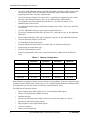
Table 2-1. Memory Configuration
DSP56F801
DSP56F803
DSP56F805
DSP56F807
Program Flash
8188 x 16-bit
32252 x 16-bit
32252 x 16-bit
61436 x 16-bit
Data Flash
2K x 16-bit
4K x 16-bit
4K x 16-bit
8K x 16-bit
Program RAM
1K x 16-bit
512 x 16-bit
512 x 16-bit
2K x 16-bit
Data RAM
1K x 16-bit
2K x 16-bit
2K x 16-bit
4K x 16-bit
Boot Flash
2K x 16-bit
2K x 16-bit
2K x16-bit
2K x 16-bit
Other than the fast Analog-to-Digital converter and the 16-bit Quadrature Timers, the most interesting
peripheral from the BLDC motor control point of view is the Pulse Width Modulation (PWM) module.
Its configuration provides the freedom to efficiently control the BLDC motor.
The PWM has the following features:
2
•
Three complementary PWM signal pairs, or six independent PWM signals
•
Features of complementary channel operation
•
Deadtime insertion
•
Separate top and bottom pulse width correction via current status inputs or software
•
Separate top and bottom polarity control
•
Edge-aligned or center-aligned PWM signals
•
15-bits of resolution
•
Half-cycle reload capability
3-Phase BLDC Motor Control with Hall Sensors