1
Target Motor Theory
•
Integral reload rates from one to 16
•
Individual software-controlled PWM outputs
•
Mask and Swap of PWM outputs
•
Programmable fault protection
•
Polarity control
•
20-mA current sink capability on PWM pins
•
Write-protectable registers
The BLDC motor control utilizes the PWM block set in the complementary PWM mode to generate
control signals for all switches of the power stage with deadtime generation. The PWM outputs can be
controlled separately by software which can set the control signal to logical 0 or 1. One feature which
is very useful for BLDC motor control is the channel swap function. The state of the control signals
can be changed immediately when required by the motor position (phase commutation) without
changing the content of the PWM value registers. These changes can be accomplished asynchronously
to the PWM duty cycle update.
3.
Target Motor Theory
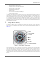
A brushless DC (BLDC) motor is a rotating electric machine where the stator is a classic three phase
stator like that of an induction motor and the rotor has surface-mounted permanent magnets (see
Figure 3-1).
Stator
Stator winding
(in slots)
Shaft
Rotor
Air gap
Permanent magnets
Figure 3-1. BLDC Motor - Cross Section
In this respect the BLDC motor is equivalent to an inverted DC commutator motor, in that the magnet
rotates while the conductors remain stationary. In the DC commutator motor, the current polarity is
reversed by the commutator and brushes, but in the brushless DC motor, the polarity reversal is
performed by a power transistor which must be switched in synchronization with the rotor position.
Therefore, the BLDC motor often has either internal or external position sensors to sense actual rotor
position.
3-Phase BLDC Motor Control with Hall Sensors
3