
1
PayLink Technical Manual
TSP129
Issue 1.5 – August 2008
PayLink
Technical Manual
This document is the copyright of Money Controls Ltd and may not be reproduced in part or in total by any means,
electronic or otherwise, without the written permission of Money Controls Ltd. Money Controls Ltd does not accept
liability for any errors or omissions contained within this document. Money Controls Ltd shall not incur any
penalties arising out of the adherence to, interpretation of, or reliance on, this standard. Money Controls Ltd will
provide full support for this product when used as described within this document. Use in applications not covered
or outside the scope of this document may not be supported. Money Controls Ltd. reserves the right to amend,
improve or change the product referred to within this document or the document itself at any time.
©Money Controls 2008. All rights reserved.
PayLink Technical Manual
TSP129
Issue 1.5 – August 2008
Contents
1.
2.
Diary of Changes ........................................................................................................................................... 8
Overview......................................................................................................................................................... 9
2.1
Introduction.............................................................................................................................................. 9
2.2
Contents ................................................................................................................................................ 11
3. Specification ................................................................................................................................................ 13
3.1
PayLink Functional block diagram ......................................................................................................... 13
3.2
PayLink Lite Functional block diagram .................................................................................................. 14
3.3
Connector Overview .............................................................................................................................. 15
3.4
Mechanical Dimensions......................................................................................................................... 17
3.5
Electrical Specification........................................................................................................................... 19
4. Installation.................................................................................................................................................... 20
4.1
Hardware installation ............................................................................................................................. 20
4.2
Software Installation .............................................................................................................................. 24
5. Interface........................................................................................................................................................ 26
5.1
Power interface...................................................................................................................................... 26
5.2
ccTalk interface ..................................................................................................................................... 26
5.3
ID003/Ardac 2 interface ......................................................................................................................... 28
5.4
PayLink Auxiliary input/output interface ................................................................................................. 29
5.5
PayLink Lite input interface.................................................................................................................... 30
5.6
Serial printer interface............................................................................................................................ 31
5.7
Serial meter interface............................................................................................................................. 31
5.8
MDB Device interface ............................................................................................................................ 32
5.9
Connector details................................................................................................................................... 32
6. Peripheral Features/Support ...................................................................................................................... 33
6.1
SR3/Condor Plus/SR5/SR5i .................................................................................................................. 33
6.2
Lumina................................................................................................................................................... 33
6.3
ccTalk hoppers ...................................................................................................................................... 34
6.4
Ardac 5 .................................................................................................................................................. 35
6.5
Serial ticket printer ................................................................................................................................. 35
6.6
MDB Device........................................................................................................................................... 35
6.7
Inputs..................................................................................................................................................... 35
6.8
Outputs .................................................................................................................................................. 35
6.9
Serial meter ........................................................................................................................................... 35
7. Using PayLink.............................................................................................................................................. 36
7.1
AESWDriver.exe.................................................................................................................................... 36
7.2
MilanDiag.exe ........................................................................................................................................ 37
7.3
Demo.exe .............................................................................................................................................. 40
7.4
Upgrading PayLink firmware.................................................................................................................. 42
8. User Manual Revision History .................................................................................................................... 43
9. Introduction.................................................................................................................................................. 44
9.1
Purpose of Document ............................................................................................................................ 44
9.2
Intended Audience................................................................................................................................. 44
9.3
Document Layout .................................................................................................................................. 44
10.
Getting Started......................................................................................................................................... 46
10.1
Installation ............................................................................................................................................. 46
10.2
Operation............................................................................................................................................... 47
10.3
OpenMHE.............................................................................................................................................. 48
10.31,1
10.31,2
10.31,3
10.31,4
10.4
OpenSpecificMHE ................................................................................................................................. 49
10.41,1
10.41,2
10.41,3
10.41,4
10.5
Synopsis .........................................................................................................................................................49
Parameters .....................................................................................................................................................49
Return Value ...................................................................................................................................................49
Remarks..........................................................................................................................................................49
EnableInterface ..................................................................................................................................... 50
10.51,1
10.51,2
10.51,3
10.51,4
10.6
Synopsis .........................................................................................................................................................48
Parameters .....................................................................................................................................................48
Return Value ...................................................................................................................................................48
Remarks..........................................................................................................................................................48
Synopsis .........................................................................................................................................................50
Parameters .....................................................................................................................................................50
Return Value ...................................................................................................................................................50
Remarks..........................................................................................................................................................50
DisableInterface..................................................................................................................................... 50
10.61,1
Synopsis .........................................................................................................................................................50
©Money Controls 2008. All rights reserved.
Page 2 of 104
PayLink Technical Manual
10.61,2
10.61,3
10.61,4
10.7
TSP129
Issue 1.5 – August 2008
Parameters .....................................................................................................................................................50
Return Value ...................................................................................................................................................50
Remarks..........................................................................................................................................................50
CurrentValue ......................................................................................................................................... 51
10.71,1
10.71,2
10.71,3
10.71,4
10.8
Synopsis .........................................................................................................................................................51
Parameters .....................................................................................................................................................51
Return Value ...................................................................................................................................................51
Remarks..........................................................................................................................................................51
PayOut................................................................................................................................................... 52
10.81,1
10.81,2
10.81,3
10.81,4
10.9
Synopsis .........................................................................................................................................................52
Parameters .....................................................................................................................................................52
Return Value ...................................................................................................................................................52
Remarks..........................................................................................................................................................52
PayStatus .............................................................................................................................................. 52
10.91,1
10.91,2
10.91,3
10.91,4
10.10
Synopsis .........................................................................................................................................................52
Parameters .....................................................................................................................................................52
Return Values. ................................................................................................................................................52
Remarks..........................................................................................................................................................52
CurrentPaid ....................................................................................................................................... 53
10.101,1
10.101,2
10.101,3
10.101,4
10.11
Synopsis .....................................................................................................................................................53
Parameters .................................................................................................................................................53
Return Value...............................................................................................................................................53
Remarks .....................................................................................................................................................53
IndicatorOn / IndicatorOff................................................................................................................... 53
10.111,1
10.111,2
10.111,3
10.12
Synopsis .....................................................................................................................................................53
Parameters .................................................................................................................................................53
Remarks .....................................................................................................................................................53
SwitchOpens / SwitchCloses ............................................................................................................. 54
10.121,1
10.121,2
10.121,3
10.121,4
Synopsis .....................................................................................................................................................54
Parameters .................................................................................................................................................54
Return Value...............................................................................................................................................54
Remarks .....................................................................................................................................................54
10.13
Getting Started Code Examples ........................................................................................................ 55
10.131 Currency Accept ............................................................................................................................ 55
10.132 Currency Payout ............................................................................................................................ 56
10.133 Indicator Example .......................................................................................................................... 57
10.134 Switch Example ............................................................................................................................. 57
11.
Full Game System.................................................................................................................................... 58
11.1
Background ........................................................................................................................................... 58
11.2
‘C’ Program Structures and Constants .................................................................................................. 58
11.21
AcceptorBlock................................................................................................................................ 59
11.21,1
11.21,2
11.22
11.22,1
11.22,2
11.23
11.23,1
11.3
Device Identity Constants .............................................................................................................. 61
Example ..........................................................................................................................................................61
Synopsis .........................................................................................................................................................62
Parameters .....................................................................................................................................................62
Return Value ...................................................................................................................................................62
Remarks..........................................................................................................................................................62
Synopsis .........................................................................................................................................................63
Parameters .....................................................................................................................................................63
Return Value ...................................................................................................................................................63
Remarks..........................................................................................................................................................63
WriteAcceptorDetails ............................................................................................................................. 63
11.51,1
11.51,2
11.51,3
11.51,4
11.6
Constants for DispenserBlock.........................................................................................................................60
Structure for DispenserBlock ..........................................................................................................................60
ReadAcceptorDetails ............................................................................................................................. 63
11.41,1
11.41,2
11.41,3
11.41,4
11.5
DispenserBlock.............................................................................................................................. 60
CurrentUpdates (1.10.4) ........................................................................................................................ 62
11.31,1
11.31,2
11.31,3
11.31,4
11.4
Constants for AcceptorBlock...........................................................................................................................59
Structures for AcceptorBlocks.........................................................................................................................59
Synopsis .........................................................................................................................................................63
Parameters .....................................................................................................................................................63
Return Value ...................................................................................................................................................63
Remarks..........................................................................................................................................................63
ReadDispenserDetails ........................................................................................................................... 64
11.61,1
11.61,2
11.61,3
11.61,4
Synopsis .........................................................................................................................................................64
Parameters .....................................................................................................................................................64
Return Value ...................................................................................................................................................64
Remarks..........................................................................................................................................................64
©Money Controls 2008. All rights reserved.
Page 3 of 104
PayLink Technical Manual
11.7
TSP129
Issue 1.5 – August 2008
WriteDispenserDetails ........................................................................................................................... 64
11.71,1
11.71,2
11.71,3
11.71,4
Synopsis .........................................................................................................................................................64
Parameters .....................................................................................................................................................64
Return Value ...................................................................................................................................................64
Remarks..........................................................................................................................................................64
11.8
Dispenser Value Reassignment (1.10.7) ............................................................................................... 65
11.9
Token Handling (Coin Ids) (1.11.x) ........................................................................................................ 65
11.10
Dual Currency Handling (Coin Ids) (1.11.x) ....................................................................................... 65
11.11
Read out of Acceptor Details (1.11.x) ................................................................................................ 66
11.12
Read out of Dispenser Details (1.11.x) .............................................................................................. 66
11.13
Coin Routing. ..................................................................................................................................... 67
11.131 Route coins to a general cash box................................................................................................. 67
11.132 Route specific coins to a specific cash box.................................................................................... 67
11.133 Route coins to a dispenser until it is full then route it to a coin cash box. ...................................... 67
11.134 Paylink Routing - Flow Diagram..................................................................................................... 68
11.14
MDB changer support. (1.10.x).......................................................................................................... 69
11.141 MDB tube level monitoring............................................................................................................. 70
11.15
Dispenser Power Fail support. (1.10.x).............................................................................................. 71
11.16
Combi Hopper Support. (1.10.x) ........................................................................................................ 71
11.17
Multiple PayLink Unit Support............................................................................................................ 72
11.171 Overview........................................................................................................................................ 72
11.172 Unit Identification ........................................................................................................................... 72
12.
Utility Functions ...................................................................................................................................... 73
12.1
CheckOperation (1.11.x)........................................................................................................................ 73
12.11,1
12.11,2
12.11,3
12.11,4
12.2
NextEvent .............................................................................................................................................. 74
12.21,1
12.21,2
12.21,3
12.21,4
12.3
Synopsis .........................................................................................................................................................77
Parameters .....................................................................................................................................................77
Return Values .................................................................................................................................................77
Remarks..........................................................................................................................................................77
USBDriverStatus.................................................................................................................................... 77
12.81,1
12.81,2
12.81,3
12.81,4
12.9
Synopsis .........................................................................................................................................................76
Parameters .....................................................................................................................................................76
Return Value ...................................................................................................................................................76
Remarks..........................................................................................................................................................76
FirmwareVersion ................................................................................................................................... 76
12.71,1
12.71,2
12.71,3
12.71,4
12.8
Synopsis .........................................................................................................................................................76
Parameters .....................................................................................................................................................76
Return Value ...................................................................................................................................................76
Remarks..........................................................................................................................................................76
SerialNumber......................................................................................................................................... 76
12.61,1
12.61,2
12.61,3
12.61,4
12.7
Synopsis .........................................................................................................................................................75
Parameters .....................................................................................................................................................75
Return Value ...................................................................................................................................................75
Remarks..........................................................................................................................................................75
SetDeviceKey ........................................................................................................................................ 76
12.51,1
12.51,2
12.51,3
12.51,4
12.6
Synopsis .........................................................................................................................................................75
Parameters .....................................................................................................................................................75
Return Value ...................................................................................................................................................75
Remarks..........................................................................................................................................................75
ValueNeeded......................................................................................................................................... 75
12.41,1
12.41,2
12.41,3
12.41,4
12.5
Synopsis .........................................................................................................................................................74
Parameters .....................................................................................................................................................74
Return Value ...................................................................................................................................................74
Remarks..........................................................................................................................................................74
AvailableValue ....................................................................................................................................... 75
12.31,1
12.31,2
12.31,3
12.31,4
12.4
Synopsis .........................................................................................................................................................73
Parameters .....................................................................................................................................................73
Return Value ...................................................................................................................................................73
Remarks..........................................................................................................................................................73
Synopsis .........................................................................................................................................................77
Parameters .....................................................................................................................................................77
Return Values .................................................................................................................................................77
Remarks..........................................................................................................................................................77
USBDriverExit........................................................................................................................................ 78
12.91,1
12.91,2
12.91,3
Synopsis .........................................................................................................................................................78
Parameters .....................................................................................................................................................78
Return Values .................................................................................................................................................78
©Money Controls 2008. All rights reserved.
Page 4 of 104
PayLink Technical Manual
12.91,4
12.10
TSP129
Issue 1.5 – August 2008
Remarks..........................................................................................................................................................78
IMHEIConsistencyError ..................................................................................................................... 79
12.101,1
12.101,2
12.101,3
12.101,4
Synopsis .....................................................................................................................................................79
Parameters .................................................................................................................................................79
Return Value...............................................................................................................................................79
Remarks .....................................................................................................................................................79
12.11
Auditing / Event Processing ............................................................................................................... 80
12.111 Structure for EventDetailBlock ....................................................................................................... 80
12.112 Event Codes for NextEvent / EventDetailBlock.............................................................................. 80
12.113 cctalk coin processing.................................................................................................................... 82
12.113,1
12.113,2
12.114
cctalk note processing ................................................................................................................... 83
12.114,1
12.114,2
12.115
12.116
Fault Events................................................................................................................................................82
Coin Events ................................................................................................................................................82
Fault Events................................................................................................................................................83
Note Events ................................................................................................................................................83
cctalk hopper processing ............................................................................................................... 84
ID-003 note processing.................................................................................................................. 86
12.116,1
Fault Events................................................................................................................................................86
13.
Note Reader Escrow................................................................................................................................ 87
13.1
EscrowEnable........................................................................................................................................ 87
13.11,1
13.11,2
13.11,3
13.2
EscrowDisable ....................................................................................................................................... 87
13.21,1
13.21,2
13.21,3
13.21,4
13.3
Synopsis .........................................................................................................................................................88
Parameters .....................................................................................................................................................88
Return Value ...................................................................................................................................................88
Remarks..........................................................................................................................................................88
EscrowAccept ........................................................................................................................................ 88
13.41,1
13.41,2
13.41,3
13.41,4
13.5
Synopsis .........................................................................................................................................................87
Parameters .....................................................................................................................................................87
Return Value ...................................................................................................................................................87
Remarks..........................................................................................................................................................87
EscrowThroughput................................................................................................................................. 88
13.31,1
13.31,2
13.31,3
13.31,4
13.4
Synopsis .........................................................................................................................................................87
Parameters .....................................................................................................................................................87
Return Value ...................................................................................................................................................87
Synopsis .........................................................................................................................................................88
Parameters .....................................................................................................................................................88
Return Value ...................................................................................................................................................88
Remarks..........................................................................................................................................................88
EscrowReturn ........................................................................................................................................ 89
13.51,1
13.51,2
13.51,3
13.51,4
Synopsis .........................................................................................................................................................89
Parameters .....................................................................................................................................................89
Return Value ...................................................................................................................................................89
Remarks..........................................................................................................................................................89
13.6
Escrow system usage............................................................................................................................ 89
14.
Meters / Counters .................................................................................................................................... 90
14.1
CounterIncrement .................................................................................................................................. 90
14.11,1
14.11,2
14.11,3
14.11,4
14.2
CounterCaption ..................................................................................................................................... 90
14.21,1
14.21,2
14.21,3
14.21,4
14.3
Synopsis .........................................................................................................................................................92
Parameters .....................................................................................................................................................92
Return Value ...................................................................................................................................................92
Remarks..........................................................................................................................................................92
ReadCounterCaption ............................................................................................................................. 92
14.41,1
14.41,2
14.41,3
14.41,4
14.5
Synopsis .........................................................................................................................................................90
Parameters .....................................................................................................................................................90
Return Value ...................................................................................................................................................91
Remarks..........................................................................................................................................................91
CounterRead ......................................................................................................................................... 92
14.31,1
14.31,2
14.31,3
14.31,4
14.4
Synopsis .........................................................................................................................................................90
Parameters .....................................................................................................................................................90
Return Value ...................................................................................................................................................90
Remarks..........................................................................................................................................................90
Synopsis .........................................................................................................................................................92
Parameters .....................................................................................................................................................92
Return Value ...................................................................................................................................................92
Remarks..........................................................................................................................................................92
CounterDisplay ...................................................................................................................................... 93
14.51,1
14.51,2
Synopsis .........................................................................................................................................................93
Parameters .....................................................................................................................................................93
©Money Controls 2008. All rights reserved.
Page 5 of 104
PayLink Technical Manual
14.51,3
14.51,4
14.6
TSP129
Issue 1.5 – August 2008
Return Value ...................................................................................................................................................93
Remarks..........................................................................................................................................................93
MeterStatus ........................................................................................................................................... 93
14.61,1
14.61,2
14.61,3
14.61,4
14.7
Synopsis .........................................................................................................................................................93
Parameters .....................................................................................................................................................93
Return Value ...................................................................................................................................................93
Remarks..........................................................................................................................................................93
MeterSerialNo........................................................................................................................................ 94
14.71,1
14.71,2
14.71,3
14.71,4
Synopsis .........................................................................................................................................................94
Parameters .....................................................................................................................................................94
Return Value ...................................................................................................................................................94
Remarks..........................................................................................................................................................94
15.11,1
15.11,2
15.11,3
15.11,4
Synopsis .........................................................................................................................................................95
Parameters .....................................................................................................................................................95
Return Value ...................................................................................................................................................95
Remarks..........................................................................................................................................................95
15.
E2Prom...................................................................................................................................................... 95
15.1
E2PromReset ........................................................................................................................................ 95
15.2
E2PromWrite ......................................................................................................................................... 96
15.21,1
15.21,2
15.21,3
15.21,4
15.3
Synopsis .........................................................................................................................................................96
Parameters .....................................................................................................................................................96
Return Value ...................................................................................................................................................96
Remarks..........................................................................................................................................................96
E2PromRead ......................................................................................................................................... 96
15.31,1
15.31,2
15.31,3
15.31,4
Synopsis .........................................................................................................................................................96
Parameters .....................................................................................................................................................96
Return Value ...................................................................................................................................................96
Remarks..........................................................................................................................................................96
16.
Bar Codes................................................................................................................................................. 97
16.1
Barcode Reading ................................................................................................................................... 97
16.2
BarcodeEnable ...................................................................................................................................... 97
16.21,1
16.21,2
16.21,3
16.3
Synopsis .........................................................................................................................................................97
Parameters .....................................................................................................................................................97
Return Value ...................................................................................................................................................97
BarcodeDisable ..................................................................................................................................... 98
16.31,1
16.31,2
16.31,3
16.31,4
16.4
Synopsis .........................................................................................................................................................98
Parameters .....................................................................................................................................................98
Return Value ...................................................................................................................................................98
Remarks..........................................................................................................................................................98
BarcodeInEscrow .................................................................................................................................. 99
16.41,1
16.41,2
16.41,3
16.41,4
16.5
Synopsis .........................................................................................................................................................99
Parameters .....................................................................................................................................................99
Return Value ...................................................................................................................................................99
Remarks..........................................................................................................................................................99
BarcodeStacked .................................................................................................................................... 99
16.51,1
16.51,2
16.51,3
16.51,4
16.6
Synopsis .........................................................................................................................................................99
Parameters .....................................................................................................................................................99
Return Value ...................................................................................................................................................99
Remarks..........................................................................................................................................................99
BarcodeAccept .....................................................................................................................................100
16.61,1
16.61,2
16.61,3
16.61,4
16.7
Synopsis .......................................................................................................................................................100
Parameters ...................................................................................................................................................100
Return Value .................................................................................................................................................100
Remarks........................................................................................................................................................100
BarcodeReturn .....................................................................................................................................100
16.71,1
16.71,2
16.71,3
16.71,4
16.8
16.9
Synopsis .......................................................................................................................................................100
Parameters ...................................................................................................................................................100
Return Value .................................................................................................................................................100
Remarks........................................................................................................................................................100
Barcode Printing ...................................................................................................................................101
BarcodePrint .........................................................................................................................................101
16.91,1
16.91,2
16.91,3
16.91,4
16.10
Synopsis .......................................................................................................................................................101
Parameters ...................................................................................................................................................101
Return Value .................................................................................................................................................101
Remarks........................................................................................................................................................101
BarcodePrintStatus...........................................................................................................................102
16.101,1
16.101,2
16.101,3
Synopsis ...................................................................................................................................................102
Parameters ...............................................................................................................................................102
Return Value.............................................................................................................................................102
©Money Controls 2008. All rights reserved.
Page 6 of 104
PayLink Technical Manual
16.101,4
TSP129
Issue 1.5 – August 2008
Remarks ...................................................................................................................................................102
17.
Engineering Support ..............................................................................................................................103
17.1
WriteInterfaceBlock...............................................................................................................................103
17.11,1
17.11,2
17.11,3
17.11,4
17.2
Synopsis .......................................................................................................................................................103
Parameters ...................................................................................................................................................103
Return Value .................................................................................................................................................103
Remarks........................................................................................................................................................103
ReadInterfaceBlock. .............................................................................................................................104
17.21,1
17.21,2
17.21,3
17.21,4
Synopsis .......................................................................................................................................................104
Parameters ...................................................................................................................................................104
Return Values ...............................................................................................................................................104
Remarks........................................................................................................................................................104
Figures
Figure 1: Functional block diagram........................................................................................................................ 13
Figure 2: Functional block diagram........................................................................................................................ 14
Figure 3: PayLink Connector overview with examples .......................................................................................... 15
Figure 4: PayLink Lite Connector overview with examples.................................................................................... 16
Figure 5: PayLink mechanical dimensions ............................................................................................................ 17
Figure 6: PayLink Lite mechanical dimensions...................................................................................................... 18
Figure 7: PayLink power interface ......................................................................................................................... 26
Figure 8: PayLink ccTalk interface......................................................................................................................... 26
Figure 9: Lumina / SR5 ccTalk interface................................................................................................................ 27
Figure 10: SR3/Condor Plus ccTalk interface........................................................................................................ 27
Figure 11: SCH2 ccTalk interface.......................................................................................................................... 27
Figure 12: SUH ccTalk interface............................................................................................................................ 28
Figure 13: PayLink - ID003/Ardac 2 interface ........................................................................................................ 28
Figure 14: Ardac 5 - ID003/Ardac 2 interface ........................................................................................................ 28
Figure 15: Connector 4 – High power outputs ....................................................................................................... 29
Figure 16: Connector 6 – Low power outputs ........................................................................................................ 29
Figure 17: Connector 10 – Switches / Inputs ......................................................................................................... 29
Figure 18: Connector 12 – Switches / Inputs ......................................................................................................... 29
Figure 19: PayLink Lite Switch Inputs.................................................................................................................... 30
Figure 19: PayLink – RS232 Serial Printer Interface ............................................................................................. 31
Figure 20: PayLink serial meter interface .............................................................................................................. 31
Figure 21: MDB Slave interface............................................................................................................................. 32
Tables
Table 1: Electrical Specification (PayLink)............................................................................................................. 19
Table 2: Electrical Specification (PayLink Lite) ...................................................................................................... 19
Table 3: Status LED table...................................................................................................................................... 20
Table 3: I/O Interface............................................................................................................................................. 30
Table 4: Hopper address Wiring & Coin Values .................................................................................................... 34
©Money Controls 2008. All rights reserved.
Page 7 of 104
PayLink Technical Manual
1.
TSP129
Issue 1.5 – August 2008
Diary of Changes
Issue 1.0…………………………………………………………………………………...…August 2005
¾ 1st Issue
Issue 1.1………………………………………………………………………………….November 2005
¾ Changed the value for cctalk hopper address 10, from 500 to 1
¾ Corrected a mistake with the pinout for RS232 printer interface
¾ Change ‘red and black’ to ‘orange and black’ for 24V
¾ Included information on hotswapping
¾ Above mentioned changes in line with firmware release 4.1.9.6
Issue 1.2…………………………………………………………………………………..December 2005
¾ Corrected a mistake with the cctalk connector pinout information.
Issue 1.3…………………………………………………………………………………….……May 2006
¾ Added hopper level sense support
¾ Added MDB changer support
¾ Added hopper power fail support
¾ Corrected mistakes in Figure 14 and Figure 15
¾ Added SCH3 Combi Support
¾ Removed all connector details – referecne now to release drawings.
¾ Added driver and dll revisions.
¾ Added additional functions available in AESWDriver and Firmware updater.
¾ Above mentioned changes in line with firmware release 4-1-10-4
Issue 1.4…………………………………………………………………………………..November 2006
¾ Changes to reflect 4-1-10-6 release of software
¾ Updated the hopper Address vs Value table
Issue 1.5………………………………………………………………………………………August 2008
¾ Changes to reflect 4-1-10-9 release of software
¾ Added PayLink Lite reference
©Money Controls 2008. All rights reserved.
Page 8 of 104
PayLink Technical Manual
2.
2.1
TSP129
Issue 1.5 – August 2008
Overview
Introduction
PayLink is a simple, compact system that offers trouble free interfacing between a PC and
money handling Equipment. PayLink allows the rapid integration of a variety of payment
peripherals into new machine platforms, without the need for bespoke software.
Designed for use in a wide range of applications
¾ Gaming
¾ Amusement
¾ Transportation
¾ Vending
Interfaces/protocols supported
¾ ccTalk
¾ ID003
¾ MDB (Master & Slave)
¾ Ardac 2
¾ RS232 serial
Products supported
¾ SR3
¾ Condor Plus / Condor Premier
¾ SR5
¾ SR5i
¾ Ardac Elite
¾ Lumina/MC7200
¾ Serial Compact Hopper MK2 (SCH2)
¾ SCH3 Combi
¾ Serial Universal Hopper (SUH)
¾ Ardac 5
¾ Serial ticket printer (GEN2)
¾ MDB Changer (Coin Co - Vortex/Quantum Pro/Guardian)
I/O supported
¾ 16 Outputs (8 High Power – 8 Low Power)
¾ 16 Inputs
¾ Serial electronic meter
©Money Controls 2008. All rights reserved.
Page 9 of 104
PayLink Technical Manual
TSP129
Issue 1.5 – August 2008
PayLink Lite, allows the connection of a range of payment peripherals (but with fewer
hoppers than PayLink) driven using the ccTalk industry-standard protocol.
Designed for use in a wide range of applications
¾ Gaming
¾ Amusement
¾ Transportation
¾ Vending
Interfaces/protocols supported
¾ ccTalk
Products supported
¾ SR3
¾ Condor Plus / Condor Premier
¾ SR5
¾ SR5i
¾ Ardac Elite
¾ Lumina/MC7200
¾ Serial Compact Hopper MK2 (SCH2)
¾ SCH3 Combi
¾ Serial Universal Hopper (SUH)
I/O supported
¾ 2 Inputs
©Money Controls 2008. All rights reserved.
Page 10 of 104
PayLink Technical Manual
2.2
TSP129
Issue 1.5 – August 2008
Contents
PayLink or PayLink Lite does not come with any cables or software. In order to obtain the
software CD (drivers, API) please contact your local Money Controls Technical Services
Dept.
The verison of software currently available and released is as follows.
PayLink Firmware
AESWDriver.exe
Aesimhei.dll
FTD2XX.dll
Demo.exe
MilanDiag.exe
4.1.10.9
1.1.3.3
1.4.0.2
3.1.8.1
1.1.0.5
1.0.3.6
To obtain a copy of these drivers please contact
Technical Services link: http://www.moneycontrols.com/support/technical_support.asp
PayLink part number:
APCUSBXX00001
PayLink Lite part number: APCUSBXX00003
However, Money Controls can provide a development kit, which consists of example cables
and a software CD, but this is only available as a 1 off order. Please contact your local
Customer Services Dept to place an order.
Customer Services link: http://www.moneycontrols.com/support/customer_support.asp
PayLink development kit part number: APCUSBXX00002
Money Controls recommend purchasing a development kit, in order to aid the integration
process in the host machine.
The contents of the PayLink Development Kit are as follows:
¾
¾
¾
¾
¾
¾
¾
¾
¾
¾
¾
¾
¾
¾
¾
¾
PayLink
1 X cctalk multidrop cable
2 X SR5/Lumina cable
1 x Ardac Elite ccTalk Cable
1 X SR3/Condor Plus cable
1 X SCH2 cable – set to address 4
1 X SUH cable – set to address 3
1 X Serial ticket printer cable
1 X Serial meter cable
1 X Paylink power cable
4 X 20-way headers – for use with inputs/outputs
1 X USB Type A – Type B cable
1 X Ardac 5 Power cable
1 X RJ45-RS232 adapter
1 X RJ45 cable
1 X MDB cable
©Money Controls 2008. All rights reserved.
Page 11 of 104
PayLink Technical Manual
TSP129
Issue 1.5 – August 2008
PayLink Lite development kit part number: APCUSBXX00004
Money Controls recommend purchasing a development kit, in order to aid the integration
process in the host machine.
The contents of the PayLink Lite Development Kit are as follows:
¾
¾
¾
¾
¾
¾
¾
¾
¾
¾
PayLink Lite
1 X cctalk multidrop cable
2 X SR5/Lumina cable
1 x Ardac Elite ccTalk Cable
1 X SR3/Condor Plus cable
1 X SCH2 cable – set to address 4
1 X SUH cable – set to address 3
1 X Paylink power cable
1 X USB Type A – Type B cable
1 X 2 way Switch Input loom
©Money Controls 2008. All rights reserved.
Page 12 of 104
PayLink Technical Manual
3.
3.1
TSP129
Issue 1.5 – August 2008
Specification
PayLink Functional block diagram
Figure 1: Functional block diagram
Note Acceptor
Coin Acceptor
Hopper
Note Acceptor
(Barcode)
Changer
Note
Acceptor
Serial ticket
Printer
Serial Meter
ccTalk
PC
U
S
B
ID003
MDB
RS232
PayLink
16
Inputs
Switches
&
Buttons
16
Output
LEDs
&
Lamps
©Money Controls 2008. All rights reserved.
Page 13 of 104
Status
LED’s
Diagnostics
&
System Info
PayLink Technical Manual
3.2
TSP129
PayLink Lite Functional block diagram
Figure 2: Functional block diagram
Note Acceptor
Coin Acceptor
Hopper
ccTalk
PC
U
S
B
PayLink Lite
2 Inputs
Switches
&
Buttons
Status
LED’s
Diagnostics
&
System Info
©Money Controls 2008. All rights reserved.
Page 14 of 104
Issue 1.5 – August 2008
PayLink Technical Manual
3.3
TSP129
Issue 1.5 – August 2008
Connector Overview
Below is an overview of each connector on PayLink.
Figure 3: PayLink Connector overview with examples
MDB Device
Serial meter
High power
Outputs
(Lamps)
Switches
(Door/float)
RS232
(Ardac5 Download/
Ticket printer)
+12V DC
(Power in)
Switches
(Door/float)
RS232 (RJ45 connector type)
- (Ardac 5 note acceptor)
Low power
Outputs
(LEDs)
ccTalk
(ccTalk peripherals)
USB Type B connector
(Connects to the USB Type A
connector on the PC)
©Money Controls 2008. All rights reserved.
Page 15 of 104
PayLink Technical Manual
TSP129
Issue 1.5 – August 2008
Figure 4: PayLink Lite Connector overview with examples
2 Switches
Not Used
+12V DC
(Power in)
ccTalk
(ccTalk peripherals)
USB Type B connector
(Connects to the USB Type A
connector on the PC)
©Money Controls 2008. All rights reserved.
Page 16 of 104
PayLink Technical Manual
3.4
TSP129
Issue 1.5 – August 2008
Mechanical Dimensions
Figure 5: PayLink mechanical dimensions
142.0
+
LES \U
ING HO
4 FIX
.00
22054
=
162.0
146.0
129.5
=
=
25.5
=
126.0
114.5
109.5
©Money Controls 2008. All rights reserved.
Page 17 of 104
PayLink Technical Manual
TSP129
Figure 6: PayLink Lite mechanical dimensions
©Money Controls 2008. All rights reserved.
Page 18 of 104
Issue 1.5 – August 2008
PayLink Technical Manual
3.5
TSP129
Issue 1.5 – August 2008
Electrical Specification
Table 1: Electrical Specification (PayLink)
Environmental
Operating temperature range
Storage temperature range
Humidity range
0°C to 55°C
-20°C to 70°C
Up to 75% RH non-condensing
Electrical - General
Voltage range
Outputs (fuse protected) +12Vdc
Outputs (fuse protected) +24Vdc
Electrical – I/O Ports
16 inputs
8 high power outputs
8 low power outputs
+10.8Vdc to +13.2Vdc (nominal +12Vdc)
2.5A continuous, 5A peak for 200ms
2.5A continuous, 5A peak for 200ms
Switch inputs 3V3 CMOS thresholds with 3V3 pull-ups, 5mA max.
Open drain up to 300mA, max output 36V. (Inductive or resistive)
Open drain up to 30mA, max output 12V (resistive only)
Communications Interface
USB Type B interface, V1.1 and above
Protocols support
ccTalk, Ardac 2, ID003, MDB, RS232
Table 2: Electrical Specification (PayLink Lite)
Environmental
Operating temperature range
Storage temperature range
Humidity range
0°C to 55°C
-20°C to 70°C
Up to 75% RH non-condensing
Electrical - General
Voltage range
Outputs (fuse protected) +12Vdc
Outputs (fuse protected) +24Vdc
Electrical – I/O Ports
2 inputs
USB Powered
2.5A continuous, 5A peak for 200ms
2.5A continuous, 5A peak for 200ms
Switch inputs 3V3 CMOS thresholds with 3V3 pull-ups, 5mA max.
Communications Interface
USB Type B interface, V1.1 and above
Protocols support
ccTalk
©Money Controls 2008. All rights reserved.
Page 19 of 104
PayLink Technical Manual
4.
4.1
TSP129
Issue 1.5 – August 2008
Installation
Hardware installation
PayLink connects to the PC via the USB Type A – Type B cable, during the installation
process; the LED indicates the current status of PayLink.
Table 3: Status LED table
RED on
RED off
RED flashing
GREEN off
GREEN flashing
GREEN on
USB not connected (electrical)
PC driver is active
No contact with PC driver program
USB not working
Application not running
Application running & Peripherals
Enabled
Connect the ccTalk multi drop cable to PayLink
Please note: Only one ccTalk
coin/note
acceptor
is
supported.
Connect the SR5 cable to the ccTalk multidrop cable and SR5.
Connect the SR3/Condor Plus cable to the ccTalk multidrop cable and SR3/Condor Plus.
©Money Controls 2008. All rights reserved.
Page 20 of 104
PayLink Technical Manual
TSP129
Issue 1.5 – August 2008
Connect the SCH2 cable to the ccTalk multidrop cable and SCH2.
Connect the SUH cable to the ccTalk multidrop cable and SUH.
Connect the Lumina cable to the ccTalk multidrop cable and Lumina.
Connect the ccTalk multidrop cable (orange and black) to a +24V dc power supply
©Money Controls 2008. All rights reserved.
Page 21 of 104
PayLink Technical Manual
TSP129
Issue 1.5 – August 2008
Connect the RJ45 cable to the PayLink and Ardac 5 (via the RJ45-RS232 adapter).
Connect the Ardac 5 power cable to the Ardac 5 and to the multi drop cable.
Connect the Serial ticket printer cable to PayLink and Serial ticket printer.
Connect the Serial meter cable to PayLink and Serial Meter.
©Money Controls 2008. All rights reserved.
Page 22 of 104
PayLink Technical Manual
TSP129
Issue 1.5 – August 2008
Connect the 4 X 20-way headers to the I/O connectors. Note: Each 20 way header has a
different ‘key way’ to correspond with the missing pin on the 20-way connectors. The ends of
the cables are left open to use as desired.
Connect PayLink to the 2-pin power cable and to a +12V dc power supply. The status LED
will show RED ON.
Connect the USB cable to PayLink and to the PC.
Windows will indicate that a new USB device has been detected and will prompt for the
drivers. The following screen will be shown (this begins the software installation).
©Money Controls 2008. All rights reserved.
Page 23 of 104
PayLink Technical Manual
4.2
TSP129
Issue 1.5 – August 2008
Software Installation
Note: These instructions are for Windows XP only. Please contact Money Controls for
information on installing the software under different operating systems.
Choose
Install
from
a
specific location, then click
Next
Choose Search for the best
driver in these locations
then click Next
If this screen appears, click
Continue Anyway
©Money Controls 2008. All rights reserved.
Page 24 of 104
PayLink Technical Manual
TSP129
Issue 1.5 – August 2008
Click Finish to complete
the software installation for
PayLink.
The PayLink is now installed and ready to use.
To complete the software installation. Take the following step:
In the PayLink Distribution CD there is a file called
Aesimhei.dll – copy this to C:\Windows\System32\
Please note: If this step is
not
performed,
the
PayLink applications will
not function correctly.
Note: At this point, in order to test PayLink. Refer to Section 7 Using PayLink
©Money Controls 2008. All rights reserved.
Page 25 of 104
PayLink Technical Manual
5.
5.1
TSP129
Issue 1.5 – August 2008
Interface
Power interface
Figure 7: PayLink power interface
Pin
1
2
5.2
Function
GND
+12V dc
ccTalk interface
Figure 8: PayLink ccTalk interface
•
•
•
•
Pin
Function
Pin
Function
1
ccTalk data line
4
+24V Out
2
+12V Out
5
0V In
3
Serial Select / 0V
6
+24V In
IMPORTANT INFORMATION
+12V Out is the supply which is provided to PayLink on the 2 pin connector via
a polyfuse for protection.
+24V In must be provided by the host machine (in the PayLink development kit,
this is shown by orange and black power cables) and is passed through a
polyfuse for protection, this becomes +24V Out.
Under no circumstances can any more than 2.5A drawn through the card.
Under no circumstances should PayLink be ‘hot swapped’
©Money Controls 2008. All rights reserved.
Page 26 of 104
PayLink Technical Manual
TSP129
Issue 1.5 – August 2008
Figure 9: Lumina / SR5 ccTalk interface
Pin
Description
Pin
1
ccTalk data line
2,3,4,5,6
Not Used
7
12V
9
8
0V
10
Description
Lumina
SR5
Not Used
ccTalk select
line
Not Used
Figure 10: SR3/Condor Plus ccTalk interface
Figure 11: SCH2 ccTalk interface
Pin
Function
Pin
Function
1
Address select 3 - MSB
6,7
0V
2
Address select 2
8
ccTalk data line
3
Address select 1 - LSB
9
N/C
+Vs
10
/RESET
4,5
The address selection process is covered in Section 6.3.
©Money Controls 2008. All rights reserved.
Page 27 of 104
PayLink Technical Manual
TSP129
Issue 1.5 – August 2008
Figure 12: SUH ccTalk interface
Pin
1
2,3
Function
Pin
Function
0V
8
Address Select 2
N.C.
9
+Vs
10,11
N.C.
4
Address Select 1 - LSB
5
ccTalk data line
6,7
View of Base plate
Connector from Rear
12
Address Select 3 - MSB
N.C.
The address selection process is covered in section 6.3
5.3
ID003/Ardac 2 interface
Figure 13: PayLink - ID003/Ardac 2 interface
Pin (PayLink)
Function
3
Rx (Green/White)
4
TX (Blue)
2
GND (Orange)
Figure 14: Ardac 5 - ID003/Ardac 2 interface
Pin (Ardac5)
Function
2
Rx (Violet)
3
TX (Yellow)
7
GND (Green)
Ardac 5 25 Way D-type (Female) Connector
Important: This view is from the mating side
©Money Controls 2008. All rights reserved.
Page 28 of 104
PayLink Technical Manual
5.4
TSP129
Issue 1.5 – August 2008
PayLink Auxiliary input/output interface
Figure 15: Connector 4 – High power outputs
+12V
0
+12V
1
N/C
2
+12V
3
+12V
N/C
+12V
4
+12V
N/C
+12V
5
Key
6
+12V
7
+12V
13
N/C
14
+12V
15
0V
5
N/C
6
0V
7
0V
13
N/C
14
0V
15
Figure 16: Connector 6 – Low power outputs
+12V
8
+12V
9
N/C
10
+12V
11
+12V
Key
+12V
12
+12V
N/C
Figure 17: Connector 10 – Switches / Inputs
0V
0
0V
1
Key
2
0V
3
0V
N/C
0V
4
0V
N/C
Figure 18: Connector 12 – Switches / Inputs
0V
8
0V
9
N/C
10
0V
11
0V
N/C
0V
12
0V
Key
©Money Controls 2008. All rights reserved.
Page 29 of 104
PayLink Technical Manual
TSP129
Issue 1.5 – August 2008
Table 4: I/O Interface
Pin
1
2
3
4
5
6
7
8
9
10
11
12
13
14
15
16
17
18
19
20
5.5
Conn 4
Output 0
+12V
Output 1
+12V
Output 2
N/C
Output 3
+12V
N/C
+12V
Output 4
+12V
N/C
+12V
Output 5
+12V
Output 6
KEYWAY
Output 7
+12V
Conn 6
Output 8
+12V
Output 9
+12V
Output 10
N/C
Output 11
+12V
KEYWAY
+12V
Output 12
+12V
N/C
+12V
Output 13
+12V
Output 14
N/C
Output 15
+12V
Conn 10
Input 0
0V
Input 1
0V
Input 2
KEYWAY
Input 3
0V
N/C
0V
Input 4
0V
N/C
0V
Input 5
0V
Input 6
N/C
Input 7
0V
Conn 12
Input 8
0V
Input 9
0V
Input 10
N/C
Input 11
0V
N/C
0V
Input 12
0V
KEYWAY
0V
Input 13
0V
Input 14
N/C
Input 15
0V
PayLink Lite input interface
Figure 19: PayLink Lite Switch Inputs
Pin - PayLink
1
2
3
4
Function
GND
Switch 1
GND
Switch 2
©Money Controls 2008. All rights reserved.
Page 30 of 104
PayLink Technical Manual
5.6
TSP129
Serial printer interface
Figure 20: PayLink – RS232 Serial Printer Interface
Pin - PayLink
1
3
5
7
5.7
Function
+24V DC
TX (from PayLink)
RX (to PayLink)
GND
Pin – Serial Printer
6
11
12
5
Serial meter interface
Figure 21: PayLink serial meter interface
This is a 1 to 1 connection
between PayLink and the
Serial meter.
Pin
(Meter)
Pin
(Meter)
Function
Function
1
SPI Data Output
4
SEC Reset
2
SPI Clock Input
5
+12V Supply
3
SPI Data Input
6
0V Supply
©Money Controls 2008. All rights reserved.
Page 31 of 104
Issue 1.5 – August 2008
PayLink Technical Manual
5.8
TSP129
Issue 1.5 – August 2008
MDB Device interface
Figure 22: MDB Slave interface
Pin (PayLink)
Function
Pin (MDB)
1
Rx (to PayLink)
5
2
TX (from PayLink)
4
3
Signal GND
6
0V DC
2
+V DC
1
Note: The MDB Master interface is currently not supported and can be used for special
projects only. Please contact Money Controls if you would like further information.
5.9
Connector details
Full drawings and connector details are provided within the \PayLink Looms section of the
CD.
©Money Controls 2008. All rights reserved.
Page 32 of 104
PayLink Technical Manual
6.
6.1
Issue 1.5 – August 2008
Peripheral Features/Support
SR3/Condor Plus/SR5/SR5i
¾
¾
¾
¾
6.2
TSP129
At present, only one coin acceptor, at address 2, is supported.
A complex system of routing is provided, which supports the diversion of coins.
Both individual coins and the entire unit can be easily inhibited.
The automatic retrieval from the unit of the value of each coin is supported.
Lumina
¾ At present, only one note acceptor, at address 40, is supported.
¾ PayLink fully supports the ccTalk encryption scheme needed to communicate with
Lumina.
¾ Both individual notes and the entire unit can be easily inhibited.
¾ The automatic retrieval from the unit of the value of each note is supported.
¾ The default Lumina 6-digit security code is 123456. To use a Lumina with a
different security code an application is provided. Luminaserial.exe is found in the
following directory
PayLink\SDK
Run LuminaSerial.exe – the following screen will be shown:
Enter the Lumina 6-digit security code (found on a label on the top of Lumina) and
click Enter. This will close the application. PayLink will now work with the code specified. To
change to a different code, run LuminaSerial.exe again to change the code.
©Money Controls 2008. All rights reserved.
Page 33 of 104
PayLink Technical Manual
6.3
TSP129
Issue 1.5 – August 2008
ccTalk hoppers
¾ Currently, 8 Hoppers, at addresses 3 to 10, are supported and the pre-set values
are linked to the cctalk address (shown below).
¾ 6 are supported on PayLink Lite (2 when a Coin or Bill acceptor are connected)
¾ The below hoppers values have been implemented from PayLink firmware version
4-1-9-6 and above.
¾ The hopper addresses is selected by hardwiring the connector.
Table 5: Hopper address Wiring & Coin Values
X = Connect to +Vs (Pins 4 or 5)
Address select 3
(Pin 1)
Address select 2
(Pin 2)
ccTalk Address
Coin
Value
3
100
4
50
5
25
6
20
7
10
8
5
9
200
10
1
Address select 1
(Pin 3)
X
X
X
X
X
X
X
X
X
X
X
X
¾ It is recommend to use only use 24V hoppers.
¾ 12V SCH2 hoppers can be used, but you must not power via PayLink, as the
current consumption will be too high. Under no circumstances can any more than 2.5A
drawn through the card.
¾ Hopper level sense is supported in PayLink firmware version 3-1-10-1 and above.
See section 7.2 Demo.exe & 11.22 DispenserBlock for information.
¾ Hopper ‘power fail’ is supported in PayLink firmware version 3-1-10-1 and above.
See section 11.15 Hopper Power Fail support. (1.10.x) for information.
©Money Controls 2008. All rights reserved.
Page 34 of 104
PayLink Technical Manual
6.4
TSP129
Issue 1.5 – August 2008
Ardac 5
¾ Paylink supports either ID003 or Ardac 2 protocol but not both. In order to convert
from Ardac 2 protocol to the ID003 protocol (and vice versa), the necessary firmware
needs to be programmed into Paylink. Refer to section 7.4 Upgrading PayLink
firmware for information on how to do this.
¾ Must be powered at 24V as the current consumption at 12V will be too high. Under
no circumstances can any more than 2.5A drawn through the card.
¾ Both individual notes and the entire unit can be easily inhibited.
¾ The automatic retrieval from the unit of the value of each note is supported.
6.5
Serial ticket printer
¾ The printer needs to be preloaded with a template.
¾ Currently only supports Futurelogic GEN2 ticket printer. Please contact Money
Controls Technical Services for details.
6.6
MDB Device
¾ The MDB hardware has always existed on the PayLink PCB. However, the
PayLink firmware only supports an MDB Device from version 3-1-10-1 and above.
6.7
Inputs
¾ 16 Individual external switches are supported by the unit, and are easily accessible
by the user’s application.
¾ Provision is made for the user’s application to easily use switches in two modes:
1. Key Press - Where a button may be pressed several times and it is important to
know how many times
2. State - Where the switch changes over a long time frame and all the application
needs to know is where the switch is at any instant.
6.8
Outputs
¾ 8 Individual external LED’s are supported by the unit, and are easily accessible by
the user’s application.
¾ 8 high power (lamp) outputs are supported by the unit, and are easily accessible by
the user’s application.
6.9
Serial meter
¾ One external meter with an SPI interface corresponding to that defined by
Starpoint is supported.
¾ The PayLink board fully supports all 31 of the Starpoint’s counters.
¾ Provision is made to allow the user’s application to easily support the BACTA
standard for displaying counter values, as well as to implement any other scheme.
¾ The PayLink board continually checks that the meter is operation.
©Money Controls 2008. All rights reserved.
Page 35 of 104
PayLink Technical Manual
7.
TSP129
Issue 1.5 – August 2008
Using PayLink
This section shows how to run and use various programs, all of which are provided on the
PayLink distribution CD.
-
7.1
AESWDriver.exe (the PayLink driver)
MilanDiag.exe (diagnostics program)
Demo.exe (API example)
Firmware.exe upgrade program
AESWDriver.exe
AESWDriver.exe is found in the PayLink directory. When the application is run, the following
screen will be shown.
You can output to a log file by adding a parameter to AESWDriver start line. This will
generate a time stamped log that will show driver and PayLink events. There will be no GUI
when this is performed.
The contents of this screen should be similar to the one shown above. The status LED on
PayLink will now Flash GREEN to indicate that the driver is working correctly.
Refer to Table 3: Status LED table for information.
This driver MUST be run before running the demo software.
©Money Controls 2008. All rights reserved.
Page 36 of 104
PayLink Technical Manual
7.2
TSP129
Issue 1.5 – August 2008
MilanDiag.exe
This is a Diagnostics program, which shows various information about PayLink, such as the
peripherals, which are connected and the version number of PayLink firmware. Diag.exe is
found in the following directory: PayLink\SDK\ When the application is run, the following
screen will be shown:
Pause – This
pauses the
application.
Clear – clears the
screen.
Mail – this opens the
default mail client so that
the information can be emailed.
Copy all – this
copies the shown
text to clipboard.
Save – This saves
the text in a log
file.
Print – This prints
the current text.
Clicking the Comment button, allows a comment to be added, the following screen will
appear.
A comment will then appear in
the diagnostics window.
©Money Controls 2008. All rights reserved.
Page 37 of 104
PayLink Technical Manual
TSP129
Issue 1.5 – August 2008
Clicking on the Show Version button will show the following screen.
This is the firmware of
PayLink.
This indicates whether Paylink
is programmed with ID003 or
Ardac 2 protocol compatible
firmware – see section 6.8
Ardac 5 for more info.
Click on the Reset Card button will show the following screen.
Choose Yes to reset PayLink.
Click on the Peripherals tab to see which peripherals are connected.
This example
shows an SR5
coin acceptor, and
information about
the coin paths and
values etc.
Click on the System Information tab to display various system information about PayLink.
©Money Controls 2008. All rights reserved.
Page 38 of 104
PayLink Technical Manual
TSP129
Click Done to close the Diagnostics application.
©Money Controls 2008. All rights reserved.
Page 39 of 104
Issue 1.5 – August 2008
PayLink Technical Manual
7.3
TSP129
Issue 1.5 – August 2008
Demo.exe
This is an API example, which also doubles up as a quick and easy way to test/demo
PayLink before the software writing can begin. The application is called Demo.exe and is in
the following location: PayLink\SDK\
Click
Switches/LEDs to
control the
Inputs/outputs
Click Acceptors to
show the current
connected Coin/Note
acceptors
Click Meter to show
the current
connected Serial
Meter
Click Dispensers to
show the current
connected Hoppers
Click Escrow for the
Escrow control
The Latest
notifies
application of
that are not
with money.
misreads etc.
Click Barcodes to
control the barcode
features (Ardac
5/Serial ticket
printer)
Event
the
events
to do
Faults,
Coins and notes entered into the
peripherals will be displayed in the
Amount Just Read box. The Total
Amount Read box is the amount read
over the lifetime of the PayLink
The Payout box shows the value to be paid
out. Click the Pay It button to pay out the
desired value. Paylink will decide how to pay
out the value depending on which value
hoppers are connected. The Total Amount
Paid Out shows the amount paid over the
lifetime of the PayLink
This drop down
menu shows the
acceptors
connected
Various information
about the selected
acceptor such as
currency, coins
programmed etc
Click Disable to
disable the
acceptor selected
Click Done to return to the front screen.
©Money Controls 2008. All rights reserved.
Page 40 of 104
PayLink Technical Manual
TSP129
Issue 1.5 – August 2008
Click on the Dispensers
button and this screen will
be
shown.
Various
information
about
the
connected Dispensers is
shown.
Click on the Switches/LEDs
button to see the following
screen.
Click on the Led buttons to
drive the LED output.
The switch box will light
when the switch inputs are
activated.
Click on the Meter button to show
this screen. The counter can be
incremented using the Increment
Counter button.
Click on the Barcodes button to show the following screen.
When a barcode is inserted, the
number will be shown here. Click
Accept ticket or Return ticket to
proceed.
The barcodes screen can be exited
using the Bar Codes Off button
©Money Controls 2008. All rights reserved.
Page 41 of 104
PayLink Technical Manual
7.4
TSP129
Issue 1.5 – August 2008
Upgrading PayLink firmware
PayLink has an on board flash device, which can be reprogrammed using a small
application through the USB link. The application is found in the following directory
PayLink\PayLink Firmware\
The following parameters can be added to the file name to provide enhanced functionality.
/Force - will automatically re-program the PayLink even if the images match.
/Check - will cause the loader to exit without showing a window if the PayLink firmware
matches, and has no errors.
/Nogui - will never display anything on the screen and will report progress to stdout or a
console window if either is available.
Once complete, the AES Programming Utility will self terminate.
While running a “Configure” button is accessible. This can be used to access advanced
features.
“Startup Configuration”
provides the ability to “Set”
and “Clear” an entry in the
Windows registry that will
silently run this copy of the
programming utility at
system Startup.
©Money Controls 2008. All rights reserved.
Page 42 of 104
PayLink Technical Manual
8.
TSP129
Issue 1.5 – August 2008
User Manual Revision History
Version
0.0 - Draft
Date
5th Feb 03
0.1 - Draft
0.2 - Draft
0.3 - Draft
0.4 - Draft
1.0
16th Feb 03
28th Feb 03
10th Apr 03
30th Apr 03
14th Oct 03
Author
D. Bush
A. Graham
D. Bush
D. Bush
D. Bush
D Bush
D Bush
1.1
24th Nov 03
D Bush
1.2
1.3
1.4
3rd Dec 03
2nd Apr 04
9th Aug 05
D Bush
D. Bush
D Bush.
1.5
8th Mar 06
D Bush
1.6
1.7
13th Nov 06
11th Sep 07
A Tainsh
D Bush
Description
Initial description document.
Detail corrections (Bug Fixes)
Changes to Coin Path handling
Minor change to SystemStatus
Further Changes to Coin Path Handling
Addition
of
Various clarifications
New Meter Functions
Changes to details on dispensers
New E2Prom Functions
Various Bug Fixes - new constants
Sections added on:
• Escrow functions.
• Event Queue
• Barcode functions
Document structure revised
Added a number of Usage Details sections
1.10.x Functions detailed
Rewritten the Coin Routing description
Added description of multiple unit support.
©Money Controls 2008. All rights reserved.
Page 43 of 104
Meters
PayLink Technical Manual
9.
TSP129
Issue 1.5 – August 2008
Introduction
9.1
Purpose of Document
This document describes the software interface to the AES Intelligent Money Handling Equipment
Interface (IMHEI) as seen by a software engineer writing in either the C or C++ programming
languages on the PC.
9.2
Intended Audience
The intended audience of this document is the software engineers who will be writing software on the
PC that will communicate with the IMHEI card itself or will read the monetary information or diagnostic
information provided by the card.
9.3
Document Layout
The document itself is split into a number of sections. Within each section, there are three sections.
•
Operational Overview.
Where the way in which this area is intended to work is explained.
•
Function Definitions.
Where you will find exact details on each function call.
•
Usage Details.
This gives details on exactly how the IMHEI system operates.
The first two sections are intended to reflect different levels of complexity at which an initial game
programmer may wish to use the interface.
1. Getting Started
These are the minimum set of “vanilla” functions that may be used to get a working
demonstration program running.
Using these calls alone; the software engineer can write a working program and get a feel for
the ease with which he can now communicate with the Money Handling Equipment attached
to his game.
2. Full Game System
These build on the set of functions provided within the “Getting Started” section. They add
functionality that can determine the status of the peripherals attached to the interface card.
By these status analysis functions, the game programmer could determine (say) the exact
reason that an attempted payout failed and then notify either and engineer or a cash collector.
3. Utility Functions
©Money Controls 2008. All rights reserved.
Page 44 of 104
PayLink Technical Manual
TSP129
Issue 1.5 – August 2008
These miscellaneous functions are concerned with the administration of the game system.
4. Note Reader Escrow
Here you will find functions that enable the escrow feature provided by note acceptors to be
easily used.
5. Meters / Counters
This section is concerned with the support of the SEC meter, a small external unit that allow
audit numbers to be maintained
6. E2Prom
2
The IMHEI units incorporate E Prom storage for internal configuration storage. Some of this is
made available to the PC programmer.
7. Barcode Reading
Here you will find functions that enable the barcoded ticket features provided by some note
acceptors to be easily used.
8. Barcode Printing
These functions are used by the IMHEI units to support a “Ticket Printer” which will produce
barcoded tickets.
9. Engineering Support
These functions provide full-blown diagnostics and reconfiguration facilities.
©Money Controls 2008. All rights reserved.
Page 45 of 104
PayLink Technical Manual
TSP129
Issue 1.5 – August 2008
10. Getting Started
10.1 Installation
The Genoa / PayLink unit is a standard USB 1.1 peripheral. Installation of the OS driver is as with any
USB peripheral, when the unit is detected the user is prompted to insert the installation CD. This CD
will install the low level drivers, which may be removed using the standard “Add or Remove Programs”
facility for the “AES Genoa USB Drivers” entry.
In addition, two other steps need to be undertaken, at present manually:
• The interface AESIMHEI.DLL needs to be copied from the installation CD to Windows\System32
• The High Level driver program needs to be copied from the installation CD to a convenient folder,
and an entry made in the Startup folder to run this at system boot.
The IMHEI card is a standard PCI interface card which has the normal Windows Plug ’n’ Play
automatic installation facilities.
When an interface card is detected in a PC the user is prompted to insert the installation CD. This CD
will configure the system to use the card and copy into the system directories the two elements of the
interface:
•
•
The device driver:
The interface:
AESIMHEI.SYS
AESIMHEI.DLL.
These provide all the software necessary to allow the user’s program to access the money handling
equipment.
©Money Controls 2008. All rights reserved.
Page 46 of 104
PayLink Technical Manual
TSP129
Issue 1.5 – August 2008
10.2 Operation
The Milan unit contains an embedded processor that is responsible for all communication with the
peripherals.
It handles the event based protocols, and uses the results to update a set of state tables.
The underlying concept behind the state tables is that the all activity causes counters to be
incremented. The application programmer reads out the totals at the time the application starts, and
then compares these with the current totals. Peripheral activity will cause these totals to increment,
subtracting the old, saved value from the current value enables the application to determine the value
inserted by the customer.
Using state tables on the PC in this way allows the programmer to be unconcerned with hardware
response times. Although the state tables have to be periodically examined to see if anything has
changed, there is never any requirement that this is done quickly, and the programmer does not have
to be concerned that the OS may suspend his program for significant periods. Regardless of how long
the program spends between examinations, the system will function perfectly and no money insertion
or payout will be missed.
The following function calls are provided to implement a minimum system. Using the functions
described within this section, one can provide a fully working system, with credit and payout capability,
as well as a number of indicators and switches.
©Money Controls 2008. All rights reserved.
Page 47 of 104
PayLink Technical Manual
TSP129
Issue 1.5 – August 2008
10.3 OpenMHE
10.31,1 Synopsis
This call is made by the PC application software to open the “Money Handling Equipment” Interface.
long OpenMHE (void);
10.31,2 Parameters
None
10.31,3 Return Value
call
the
Open
If
succeeds
then
the
value
zero
is
returned.
In the event of a failure one of the following standard windows error codes will be returned, either as a
direct echo of a Windows API call failure, or to indicate internally detected failures that closely
correspond
to
the
quoted
meanings.
Error
Number
13
20
21
31
170
1167
Suggested string for
English
decoding
The DLL, application or device are at
incompatible revision levels.
The system cannot find the device
specified.
The device is not ready.
Driver program not running. or No PCI
card in system.
The USB link is in use.
The device is not connected.
Microsoft Mnemonic
Retry
ERROR_INVALID_DATA
No
ERROR_BAD_UNIT
No
ERROR_NOT_READY
ERROR_GEN_FAILURE
Yes
Yes
ERROR_BUSY
ERROR_DEVICE_NOT_CONNECTED
Yes
Yes
10.31,4 Remarks
1. With a USB system, there is a noticeable time for the USB communications to start. This may
cause error returns labelled “Yes” under Retry in the above table. This indicates that the call to
OpenMHE should be retried periodically until it has failed for at least 5 consecutive seconds
before deciding that the interface is actually inoperative.
2. Whereas an Open service normally requires a description of the item to be opened (and
returns a reference to that Item) there is only one IMHE Interface unit in a system. Hence any
“Open” call must refer to that single item.
3. Even following this call, all the money handling equipment will be disabled and rejecting all
currency inserted until the successful execution of a call to EnableInterface.
©Money Controls 2008. All rights reserved.
Page 48 of 104
PayLink Technical Manual
TSP129
Issue 1.5 – August 2008
10.4 OpenSpecificMHE
10.41,1 Synopsis
This call is made by the PC application software to open or to switch to one of the multiple “Money
Handling Equipment” Interfaces installed on the PC.
Details on how a system works with multiple PayLinks are given in a later section.
long OpenSpecificMHE (char SerialNo[8]);
10.41,2 Parameters
None
10.41,3 Return Value
If the Open call succeeds then the value zero is returned.
In the event of a failure the same standard windows error codes are returned as for OpenMHE.
10.41,4 Remarks
1. Every PayLink requires a unique instance of the USB driver program to be running. If there is
no driver for the PayLink whose Serial Number is quoted, then the function returns 31
(ERROR_GEN_FAILURE).
2. As the default serial number for PayLink unit is “AE000001”, the OpenMHE call is equivalent
to the call OpenSpecficMHE("AE000001")
3. This call may be issued repeatedly with no ill effects. Each call will serve to swap all the other
calls in this document to the specified unit.
©Money Controls 2008. All rights reserved.
Page 49 of 104
PayLink Technical Manual
TSP129
Issue 1.5 – August 2008
10.5 EnableInterface
10.51,1 Synopsis
The EnableInterface call is used to allow “turn on” the IMHE. This would be called when a game is
initialised and ready. Until this call is made, no acceptors will accept credit.
void EnableInterface (void) ;
10.51,2 Parameters
None
10.51,3 Return Value
None
10.51,4 Remarks
1. Normally the application will initialise the saved values of all the information it is monitoring
before this call.
2. This must be called following the call to OpenMHE before any coins / notes will be registered.
10.6 DisableInterface
10.61,1 Synopsis
The DisableInterface call is used to prevent users from entering any more coins or notes.
void DisableInterface (void) ;
10.61,2 Parameters
None
10.61,3 Return Value
None
10.61,4 Remarks
1. There is no guarantee that a coin or note can not be successfully read after this call has been
made, a successful read may be in progress.
©Money Controls 2008. All rights reserved.
Page 50 of 104
PayLink Technical Manual
TSP129
Issue 1.5 – August 2008
10.7 CurrentValue
10.71,1 Synopsis
Determine the current monetary value that has been accepted
The CurrentValue call is used to determine the total value of all coins and notes read by the money
handling equipment connected to the interface.
long CurrentValue (void) ;
10.71,2 Parameters
None
10.71,3 Return Value
The current value, in the lowest denomination of the currency (i.e. cents / pence etc.) of all coins and
notes read.
10.71,4 Remarks
1. The value returned by this call is never reset, but increments for the life of the interface card.
Since this is a long (32 bit) integer, the card can accept £21,474,836.47 of credit before it runs
into any rollover problems. This value is expected to exceed the life of the game.
2. It is the responsibility of the application to keep track of value that has been used up and to
monitor for new coin / note insertions by increases in the returned value.
3. Note that this value should be read following the call to OpenMHE and before the call to
EnableInterface to establish a starting point before any coins or notes are read.
©Money Controls 2008. All rights reserved.
Page 51 of 104
PayLink Technical Manual
TSP129
Issue 1.5 – August 2008
10.8 PayOut
10.81,1 Synopsis
The PayOut call is used by the PC application to instruct the interface to pay out coins (or notes).
void PayOut (long Value) ;
10.81,2 Parameters
Value
This is the value, in the lowest denomination of the currency (i.e. cents / pence etc.) of the coins and
notes to be paid out.
10.81,3 Return Value
None
10.81,4 Remarks
1. This function operates in value, not coins. It is the responsibility of the interface to decode this
and to choose how many coins (or notes) to pay out, and from which device to pay them.
10.9 PayStatus
10.91,1 Synopsis
The PayStatus call provides the current status of the payout process.
long LastPayStatus (void) ;
10.91,2 Parameters
None
10.91,3
Value
0
1
-1
-2
-3
-4
-5
-6
-7
-8
Return Values.
Meaning
The interface is in the process of paying out
The payout process is up to date
The dispenser is empty
The dispenser is jammed
Dispenser non functional
Dispenser shut down due to fraud attempt
The dispenser is blocked
No Dispenser matches amount to be paid
The dispenser is inhibited
The internal self checks failed
Mnemonic
PAY_ONGOING
PAY_FINISHED
PAY_EMPTY
PAY_JAMMED
PAY_US
PAY_FRAUD
PAY_FAILED_BLOCKED
PAY_NO_HOPPER
PAY_INHIBITED
PAY_SECURITY_FAIL
10.91,4 Remarks
1. Following a call to PayOut, the programmer should poll this to check the progress of the
operation.
2. If one out of multiple hoppers has a problem, the PCI card will do the best it can. If it can not pay
out the entire amount, the status will reflect the last attempt.
©Money Controls 2008. All rights reserved.
Page 52 of 104
PayLink Technical Manual
TSP129
Issue 1.5 – August 2008
10.10 CurrentPaid
10.101,1 Synopsis
The CurrentPaid call is available to keep track of the total money paid out because of calls to the
PayOut function.
long CurrentPaid (void) ;
10.101,2
Parameters
None
10.101,3 Return Value
The current value, in the lowest denomination of the currency (i.e. cents / pence etc.) of all coins and
notes ever paid out.
10.101,4 Remarks
1. This value that is returned by this function is updated in real time, as the money handling
equipment succeeds in dispensing coins.
2. The value that is returned by this call is never reset, but increments for the life of the interface
card. It is the responsibility of the application to keep track of starting values and to monitor for
new coin / note successful payments by increases in the returned value.
3. Note that this value can be read following the call to OpenMHE and before the call to
EnableInterface to establish a starting point before any coins or notes are paid out.
10.11 IndicatorOn / IndicatorOff
10.111,1 Synopsis
The IndicatorOn / IndicatorOff calls are used by the PC application to control LED’s and indicator
lamps connected to the interface.
void IndicatorOn (long IndicatorNumber) ;
void IndicatorOff (long IndicatorNumber) ;
10.111,2
IndicatorNumber
Parameters
This is the number of the Lamp that is being controlled.
Return Value
None
10.111,3 Remarks
1. Although the interface is described in terms of lamps, any equipment at all may in fact be
controlled by these calls, depending only on what is physically connected to the interface card.
©Money Controls 2008. All rights reserved.
Page 53 of 104
PayLink Technical Manual
TSP129
Issue 1.5 – August 2008
10.12 SwitchOpens / SwitchCloses
10.121,1 Synopsis
The calls to SwitchOpens and SwitchCloses are made by the PC application to read the state of
switches connected to the interface card.
long SwitchOpens (long SwitchNumber) ;
long SwitchCloses (long SwitchNumber) ;
10.121,2 Parameters
SwitchNumber
This is the number of the switch that is being controlled. In principle the API can support 64
switches, though note that not all of these may be support by any particular hardware unit.
10.121,3 Return Value
The number of times that the specified switch has been observed to open or to close, respectively.
10.121,4 Remarks
1. The convention is that at initialisation time all switches are open, a switch that starts off closed
will therefore return a value of 1 to a SwitchCloses call immediately following the OpenMHE
call.
2. The expression (SwitchCloses(n) == SwitchOpens(n)) will always return 0 if the switch is
currently closed and 1 if the switch is currently open.
3. Repeat pressing / tapping of a switch by a user will be detected by an increment in the value
returned by SwitchCloses or SwtichOpens.
4. The user only needs to monitor changes in one of the two functions (in the same way as most
windowing interfaces only need to provide functions for button up or button down events)
5. The inputs are debounced. The unit reads all 16 inputs every 2 milliseconds. If we detect a
change, we then require the next two reads to give exactly the same pattern before reporting
the change. This means that a simple "electronic" input change will be reported between 4
and 6 milliseconds of it occurring.
©Money Controls 2008. All rights reserved.
Page 54 of 104
PayLink Technical Manual
TSP129
Issue 1.5 – August 2008
10.13 Getting Started Code Examples
The following code fragments are intended to provide clear examples of how the calls to the IMHEI are
designed to be used:
Each function will provide the central processing for a small command line demonstration program.
10.131 CURRENCY ACCEPT
void AcceptCurrencyExample(int NoOfChanges)
{
long LastCurrencyValue ;
long NewCurrencyValue ;
long OpenStatus = OpenMHE() ;
if (OpenStatus != 0)
{
printf("IMHEI open failed - %ld\n", OpenStatus) ;
}
else
{
// Then the open call was successful
// Currency acceptance is currently disabled
LastCurrencyValue = CurrentValue() ;
printf("Initial currency accepted = %ld pence\n",
LastCurrencyValue) ;
EnableInterface() ;
printf("Processing %d change events\n", NoOfChanges) ;
while (NoOfChanges > 0)
{
Sleep(100) ;
NewCurrencyValue = CurrentValue() ;
if (NewCurrencyValue != LastCurrencyValue)
{
// More money has arrived (we do not care where from)
printf("The user has just inserted %ld pence\n",
NewCurrencyValue - LastCurrencyValue) ;
LastCurrencyValue = NewCurrencyValue ;
--NoOfChanges ;
}
}
}
}
©Money Controls 2008. All rights reserved.
Page 55 of 104
PayLink Technical Manual
TSP129
Issue 1.5 – August 2008
10.132 CURRENCY PAYOUT
void PayCoins(int NoOfCoins)
{
long OpenStatus = OpenMHE() ;
if (OpenStatus != 0)
{
printf("IMHEI open failed - %ld\n", OpenStatus) ;
}
else
{
// Then the open call was successful
// The interface is currently disabled
EnableInterface() ;
PayOut(NoOfCoins * 100) ;
while (LastPayStatus() == 0)
{}
if (LastPayStatus() < 0)
{
printf("Error %d when paying %d coins\n",
LastPayStatus(), NoOfCoins) ;
}
else
{
printf("%d coins paid out\n", NoOfCoins) ;
}
}
}
©Money Controls 2008. All rights reserved.
Page 56 of 104
PayLink Technical Manual
TSP129
Issue 1.5 – August 2008
10.133 INDICATOR EXAMPLE
void LEDs(void)
{
long OpenStatus = OpenMHE() ;
char Loop ;
if (!OpenStatus)
{
EnableInterface() ;
for (Loop = 0 ; Loop < 8 ; ++Loop)
{
IndicatorOn(Loop) ;
Sleep(1000) ;
}
for (Loop = 0 ; Loop < 8 ; ++Loop)
{
IndicatorOff(Loop) ;
Sleep(1000) ;
}
DisableInterface() ;
}
}
10.134 SWITCH EXAMPLE
void LEDs(void)
{
long OpenStatus = OpenMHE() ;
char Loop ;
if (!OpenStatus)
{
EnableInterface() ;
for (Loop = 0 ; Loop < 8 ; ++Loop)
{
printf(“Switch %d is currently %s\n”, Loop,
SwitchCloses(Loop) == SwitchOpens(Loop) ?
“Open” : “Closed”) ;
printf(“It has closed %d times!\n”, SwitchCloses(Loop)) ;
}
DisableInterface() ;
}
}
©Money Controls 2008. All rights reserved.
Page 57 of 104
PayLink Technical Manual
TSP129
Issue 1.5 – August 2008
11. Full Game System
11.1 Background
When implementing a full game implementation, tighter control over the behaviour and response of
the individual acceptors and hoppers is frequently necessary, for such purposes as routing coins to
hoppers and cashboxes and emptying hoppers. Some more details on these operations are given at
the end of this section.
The data retrieval functionality is achieved by reading the control blocks for the acceptors (with
ReadAcceptorDetails) and possibly hoppers (with ReadDispenserDetails) at initialisation time and
then continually checking the current contents of these against saved copies. To aid in this process
the CurrentUpdates function guarantees that; if it returns an unchanged value then none of the
control blocks will have changed.
Most of the control functionality is achieved by reading a data structure from the API, modifying it as
appropriate or necessary and writing it back. Four functions are involved: ReadAcceptorDetails,
ReadDispenserDetails, WriteAcceptorDetails & WriteDispenserDetails.
All these functions identify the individual units by a serial number, in the range 0…N-1. The
programmer should not assume that any particular unit is present at any particular number, the
numbers are assigned dynamically and are liable to change from run to run.
To find the particular unit of interest, the programmer should scan number from 0 up, looking for a
match on the structure members.
For an acceptor, this will usually involve the Unit field. Although this is defined as single 32 bit
number, it is created by concatenating four 8 bit values. The program will usually only be interested in
distinguishing the coin and note acceptors, which are distinguished by values in the top 8 bits. For this
purpose two ‘C’ macros are defined, IS_COIN_ACCEPTOR(Unit) and IS_NOTE_ACCEPTOR(Unit),
see below, which can easily be translated into other languages.
For a dispenser, this will normally involve the Value as that shows the coin value assumed by Milan
interface, which is the most important distinguishing feature of a dispenser.
11.2 ‘C’ Program Structures and Constants
This is currently an extract of the ‘C’ header file, the comments should serve to define the various
fields, we hope to enhance the format of this section of the document in the near future.
For people unfamiliar with ‘C’, a data item prefixed with long is a 32 bit integer, a data item prefixed
with char is an 8 bit integer.
©Money Controls 2008. All rights reserved.
Page 58 of 104
PayLink Technical Manual
TSP129
Issue 1.5 – August 2008
11.21 ACCEPTORBLOCK
11.21,1 Constants for AcceptorBlock
enum AcceptorConstants
{
ACCEPTOR_DEAD
ACCEPTOR_DISABLED
ACCEPTOR_INHIBIT
ACCEPTOR_FRAUD
ACCEPTOR_BUSY
ACCEPTOR_FAULT
=
=
=
=
=
=
0x00000001,
0X00000004,
0X00000008,
0x00000010,
0x00000020,
0x00000040,
MAX_ACCEPTOR_COINS = 256
/*
/*
/*
/*
/*
/*
No response to communications for this device */
Disabled by Interface */
Specific by Application */
Reported from device */
Reported from device */
Reported from device */
/* Maximum coins or notes */
/* handled by any device */
} ;
11.21,2 Structures for AcceptorBlocks
typedef struct
{
long
long
long
long
long
long
char
char
char
char
char*
Value ;
Inhibit ;
Count ;
Path ;
PathCount ;
PathSwitchLevel ;
//
//
//
//
//
//
DefaultPath ;
FutureExpansion ;
HeldInEscrow ;
FutureExpansion2 ;
CoinName ;
//
//
//
//
Value of this coin
Set by PC: this coin is inhibited
Total number read "ever"
Set by PC: this coin's chosen output path
Number "ever" sent down the chosen Path
Set by PC: PathCount level to switch coin to default
path
Set by PC: Default path for this specific coin
Set by PC: for future use
count of this note / coin in escrow (usually max 1)
for future use
// A string, usually as returned from the acceptor,
describing this coin
} AcceptorCoin ;
typedef struct
{
long
long
long
long
long
long
long
char
Unit ;
Status ;
NoOfCoins ;
InterfaceNumber ;
UnitAddress ;
DefaultPath ;
EventCount ;
Currency[4] ;
//
//
//
//
//
Specification of this unit
AcceptorStatuses - zero if device OK
The number of different coins handled
The bus / connection
For addressable units
// Count of events (e.g. rejects) for this acceptor
// Main currency code reported by an intelligent
acceptor
AcceptorCoin
Coin[MAX_ACCEPTOR_COINS] ; // (only NoOfCoins are set up)
long
SerialNumber ;
// Reported serial number (0 if N/A)
char*
Description ;
// Device specific string for type / revision / coin
set
} AcceptorBlock ;
©Money Controls 2008. All rights reserved.
Page 59 of 104
PayLink Technical Manual
TSP129
Issue 1.5 – August 2008
11.22 DISPENSERBLOCK
11.22,1 Constants for DispenserBlock
enum DispenserConstants
{
MAX_DISPENSERS
= 16
// Maximum handled
// Coin Count Status Values
DISPENSER_COIN_NONE
= 0,
//
DISPENSER_COIN_LOW
= 1,
//
DISPENSER_COIN_MID
= 2,
//
DISPENSER_COIN_HIGH
= 3,
//
DISPENSER_ACCURATE
= -1,
DISPENSER_ACCURATE_FULL = -2,
DISPENSER_REASSIGN_VALUE
No dispenser coin reporting
Less than the low sensor level
Above low sensor but below high
High sensor level reported
// Coin Count reported by Dispenser
// The Dispenser is full
=
100,
//
The Value has just been updated by the
application
// The updated Value has just been accepted by the
IMHEI
DISPENSER_VALUE_REASSIGNED = 101
} ;
11.22,2 Structure for DispenserBlock
typedef struct
{
long
long
long
long
long
long
long
long
Unit ;
Status ;
InterfaceNumber ;
UnitAddress ;
Value ;
Count ;
Inhibit ;
Currency ;
long
CoinCount ;
long
CoinCountStatus ;
long
SerialNumber ;
char*
Description ;
} DispenserBlock ;
//
//
//
//
//
//
//
//
//
//
//
//
//
//
Specification of this unit
Individual Dispenser status
This takes the same values as PayStatus()
The bus / connection
For addressable units
The value of the coins in this dispensor
Number dispensed according to the hopper records
Set to 1 to inhibit Dispenser
The currency code reported by
an intelligent dispenser
The number of coins in the dispenser
Flags Relating to Coin Count (See above)
Reported serial number (0 if N/A)
Device specific string for type / revision
©Money Controls 2008. All rights reserved.
Page 60 of 104
PayLink Technical Manual
TSP129
Issue 1.5 – August 2008
11.23 DEVICE IDENTITY CONSTANTS
These constants are ORed together to form the coded device identity that can be extracted from the
interface.
11.23,1 Example
As an example, a Money Controls Serial Compact Hopper 2 will have the following device code
DP_MCL_SCH2, made up from:
•
•
•
•
A device specifc code
ORed with
DP_COIN_PAYOUT_DEVICE
ORed with
DP_CCTALK_INTERFACE
ORed with
DP_MANU_MONEY_CONTROLS
This is a device code of
enum GenericDevices
{
DP_GENERIC_MASK
0x01020101
=
0xff000000,
DP_COIN_ACCEPT_DEVICE
DP_NOTE_ACCEPT_DEVICE
DP_CARD_ACCEPT_DEVICE
=
=
=
0x02000000,
0x12000000,
0x22000000,
DP_COIN_PAYOUT_DEVICE
DP_NOTE_PAYOUT_DEVICE
DP_CARD_PAYOUT_DEVICE
} ;
=
=
=
0x01000000,
0x11000000,
0x21000000
#define
#define
#define
#define
IS_ACCEPTOR(code)
IS_COIN_ACCEPTOR(code)
IS_NOTE_ACCEPTOR(code)
IS_PAYOUT(code)
(code & 0x02000000)
((code & DP_GENERIC_MASK) == DP_COIN_ACCEPT_DEVICE)
((code & DP_GENERIC_MASK) == DP_NOTE_ACCEPT_DEVICE)
(code & 0x01000000)
enum InterfaceNumbers
{
// These describe the interface via which this device is connected:
DP_INTERFACE_MASK
= 0x00ff0000,
DP_INTERFACE_UNIT
= 0x00000000,
DP_ONBOARD_PARALLEL_INTERFACE = 0x00010000,
DP_CCTALK_INTERFACE
= 0x00020000,
DP_SSP_INTERFACE
= 0x00030000,
DP_HII_INTERFACE
= 0x00040000,
DP_ARDAC_INTERFACE
= 0x00050000,
DP_JCM_INTERFACE
= 0x00060000,
DP_GPT_INTERFACE
= 0x00070000,
DP_MDB_INTERFACE
= 0x00080000,
DP_MDB_LEVEL_3_INTERFACE
= 0x00080000,
DP_MDB_LEVEL_2_INTERFACE
= 0x00090000,
// Some Generic Identities
DP_ID003_NOTE
= 0 | DP_JCM_INTERFACE
| DP_NOTE_ACCEPT_DEVICE,
DP_MDB_LEVEL_2
= 0 | DP_MDB_LEVEL_2_INTERFACE
| DP_COIN_ACCEPT_DEVICE,
DP_MDB_LEVEL_3
= 0 | DP_MDB_LEVEL_3_INTERFACE
| DP_COIN_ACCEPT_DEVICE,
DP_MDB_LEVEL_2_TUBE
= 0 | DP_MDB_LEVEL_2_INTERFACE
| DP_COIN_PAYOUT_DEVICE,
DP_MDB_TYPE_3_PAYOUT
= 0 | DP_MDB_LEVEL_3_INTERFACE
| DP_COIN_PAYOUT_DEVICE,
DP_MDB_BILL
= 0 | DP_MDB_INTERFACE
| DP_NOTE_ACCEPT_DEVICE,
DP_CC_GHOST_HOPPER
= 255 | DP_CCTALK_INTERFACE
// Used by Value hopperz
| DP_COIN_PAYOUT_DEVICE,
} ;
#define GET_INTERFACE(code) ((code >> 16) & 0xff)
©Money Controls 2008. All rights reserved.
Page 61 of 104
PayLink Technical Manual
enum ManufacturerIdentities
{
DP_MANUFACTURER_MASK
DP_MANU_UNKNOWN
DP_MANU_MONEY_CONTROLS
DP_MANU_INNOVATIVE_TECH
DP_MANU_MARS_ELECTRONICS
DP_MANU_AZKOYEN
DP_MANU_NRI
DP_MANU_ICT
DP_MANU_JCM
DP_MANU_GPT
DP_MANU_COINCO
DP_MANU_ASAHI_SEIKO
DP_MANU_ASTROSYSTEMS
} ;
TSP129
Issue 1.5 – August 2008
// These describe the manufacturer of the device.
= 0x0000ff00,
= 0x00000000,
= 0x00000100,
= 0x00000200,
= 0x00000300,
= 0x00000400,
= 0x00000500,
= 0x00000600,
= 0x00000700,
= 0x00000800,
= 0x00000900,
= 0x00000A00,
= 0x00000B00,
enum ManufacturerSpecificDeviceTypes
{
// These device types are manufacturer-dependent,
//
so that each manufacturer can have up to 255 known devices.
DP_SPECIFIC_DEVICE_MASK
= 0x000000ff,
DP_MCL_SCH2
=
// Money Controls Devices
1 | DP_MANU_MONEY_CONTROLS
| DP_CCTALK_INTERFACE
| DP_COIN_PAYOUT_DEVICE,
Please see the latest AESIMHEI.H file in the SDK for an up to date list of these.
DP_AS_WH2
=
// Asahi Seiko Devices
0 | DP_MANU_ASAHI_SEIKO
| DP_CCTALK_INTERFACE
| DP_COIN_PAYOUT_DEVICE,
} ;
11.3 CurrentUpdates (1.10.4)
11.31,1 Synopsis
Detect updates to the data presented to the API by the firmware.
The fact that the value returned by CurrentUpdates has changed, prompts the application to reexamine all the variable data in which it is interested.
long CurrentUpdates (void) ;
11.31,2 Parameters
None
11.31,3 Return Value
Technically CurrentUpdates returns the number of times that the API data has been updated since
the PC system initialised. In practice, only changes in this value are significant.
11.31,4 Remarks
1. It is possible that the value could change without any visible data changing.
2. This is only available with the DLL associated with firmware versions 1.10.8 and higher.
©Money Controls 2008. All rights reserved.
Page 62 of 104
PayLink Technical Manual
TSP129
Issue 1.5 – August 2008
11.4 ReadAcceptorDetails
11.41,1 Synopsis
The ReadAcceptorDetails call provides a snapshot of all the information possessed by the interface on
a single unit of money handling equipment.
bool ReadAcceptorDetails ( long
Number,
AcceptorBlock* Snapshot) ;
11.41,2 Parameters
1. Number
The serial number of the coin or note acceptor about which information is required.
2. Snapshot
A pointer to a program buffer into which all the information about the specified acceptor will be
copied.
11.41,3 Return Value
True if the specified input device exists, False if the end of the list is reached.
11.41,4 Remarks
The serial numbers of the acceptors are contiguous and run from zero upwards.
11.5 WriteAcceptorDetails
11.51,1 Synopsis
The WriteAcceptorDetails call updates all the changeable information to the interface for a single unit
of money accepting equipment.
void WriteAcceptorDetails ( long
Number,
AcceptorBlock* Snapshot) ;
11.51,2 Parameters
1. Number
The serial number of the coin or note acceptor being configured.
2. Snapshot
A pointer to a program buffer containing the configuration data for the specified acceptor. See
below for details.
11.51,3 Return Value
None.
11.51,4 Remarks
The serial numbers of the acceptors are contiguous and run from zero upwards.
A call to ReadAcceptorDetails followed by call to WriteAcceptorDetails for the same data will have
no effect on the system.
©Money Controls 2008. All rights reserved.
Page 63 of 104
PayLink Technical Manual
TSP129
Issue 1.5 – August 2008
11.6 ReadDispenserDetails
11.61,1 Synopsis
The ReadDispenserDetails call provides a snapshot of all the information possessed by the interface
on a single unit of money dispensing equipment.
bool ReadDispenserDetails( long
Number,
DispenserBlock* Snapshot) ;
11.61,2 Parameters
1. Number
The serial number of the coin or note dispenser about which information is required.
2. Snapshot
A pointer to a program buffer, into which all the information about the specified dispenser will
be copied.
11.61,3 Return Value
True if the specified input device exists, False if the end of the list is reached.
11.61,4 Remarks
The serial numbers of the dispensers are contiguous and run from zero upwards.
11.7 WriteDispenserDetails
11.71,1 Synopsis
The WriteDispenserDetails call updates all the changeable information to the interface for a single
unit of money handling equipment.
void WriteDispenserDetails( long
Number,
DispenserBlock* Snapshot) ;
11.71,2 Parameters
1. Number
The serial number of the coin or note dispenser being configured.
2. Snapshot
A pointer to a program buffer containing the configuration data for the specified dispenser. See
below for details.
11.71,3 Return Value
None.
11.71,4 Remarks
The serial numbers of the dispensers are contiguous and run from zero upwards. A call to
ReadDispenserDetails followed by call to WriteDispenserDetails for the same data will have no effect
on the system.
©Money Controls 2008. All rights reserved.
Page 64 of 104
PayLink Technical Manual
TSP129
Issue 1.5 – August 2008
11.8 Dispenser Value Reassignment (1.10.7)
Releases of PayLink after 1.10.7 allow the value of the coin associated with a Dispenser to be reassigned.
To do this:
• the dispenser to be updated should be found using ReadDispenserDetails(),
• the Dispenser.Value updated to the new value,
• the Dispenser.Status field changed to DISPENSER_REASSIGN_VALUE
• and WriteDispenserDetails() used to update the record to Paylink.
•
Paylink will acknowledge that the update has been processed by setting the Dispenser.Status
field to DISPENSER_VALUE_REASSIGNED. If this value is not seen in the Dispenser.Status
field, then the value change has not be processed by Paylink.
11.9 Token Handling (Coin Ids) (1.11.x)
As tokens do not have a known value, they appear as coins with value zero. The only way for a game
to detect tokens is to use the CurrentUpdates() function to detect activity, and then to check for
increases in the count of the token(s) to be accepted(Coin.Count).
The index for the coin that holds the count for a particular token can be obtained by searching the coin
array belonging to the acceptor and comparing the coin name (Coin.CoinName) with that of the
token.
11.10 Dual Currency Handling (Coin Ids) (1.11.x)
If an acceptor is being used to accept coins of more than one currency, the application can determine
the currency of a specific coin by examining the first two characters of the name of the coin
(Coin.CoinName). For supported acceptors, the firmware guarantees that a coin name will always
contain a currency code as the first two characters of a coin name.
ccTalk
ID-003
MDB
GPT
ARDAC
This contains up to eight characters as returned by the Request Coin Id (184)
command.
This contains a representation of the three bytes as return by the Get Currency
Assignment (0x8A) command. The first two bytes are the hex value for country code,
then a ‘/’, then the base value as a decimal number, followed by a ‘^’, then the count
of extra zeros as a decimal number.
TBD
TBD
The Ardac protocol does not return any information about notes.
©Money Controls 2008. All rights reserved.
Page 65 of 104
PayLink Technical Manual
TSP129
Issue 1.5 – August 2008
11.11 Read out of Acceptor Details (1.11.x)
Different
protocols
/
manufacturers
provide
different
Acceptor.Description field is generated as follows:
ccTalk
ID-003
MDB
GPT
ARDAC
details
on
acceptors.
The
The replies to:
• Request Currency Specification ID (91),
• Request Currency Revision (145),
• Request Software Revision (241) &
• Request Product Code (244) commands, separated by ‘~’ characters.
Each individual field is truncated to 15 characters, and is omitted if there is no
response to the command, although the ‘~’ character is still inserted.
The entire reply to the “Get Version Request” (0x88) command
TBD
TBD
TBD.
The Acceptor.SerialNumber field is generated as follows:
ccTalk
ID-003
MDB
GPT
ARDAC
The binary reply to the ID Serial No (242) command.
The “standard” ID-003 protocol does not allow for a serial number. A non-standard
0x8F query is issued and any response will be stored here.
TBD
TBD
TBD.
11.12 Read out of Dispenser Details (1.11.x)
Different protocols / manufacturers provide different details on acceptors. The Description
(Dispenser.Description) field is generated as follows:
ccTalk
MDB
The replies to:
• Request Software Revision (241) &
• Request Product Code (244) commands, separated by ‘~’ characters.
Each individual field is truncated to 15 characters, and is omitted if there is no
response to the command, although the ‘~’ character is still inserted.
TBD
The Dispenser.SerialNumber field is generated as follows:
ccTalk
MDB
The binary reply to the ID Serial No (242) command.
TBD
©Money Controls 2008. All rights reserved.
Page 66 of 104
PayLink Technical Manual
TSP129
Issue 1.5 – August 2008
11.13 Coin Routing.
Coins can be easily routed to fill a coin dispenser and one or more cash boxes.
There are 3 routing techniques:
• Route coins to a general cash box.
• Route specific coins to a specific cash box.
• Route specific coins to a dispenser until it is full then route it to a coin specific cash box.
There are 3 settings for each coin that are important:
• Coin.Path
The path to the coin specific hopper.
• Coin.DefaultPath
The path to the coin specific cash box.
• Coin.PathSwitchLevel
When Coin.PathCount reaches Coin.PathSwitchLevel coins are
routed to the coin cash box.
11.131 ROUTE COINS TO A GENERAL CASH BOX
• Set all coin paths to the desired route.
e.g. General Cash box on route 4.
• Path
• DefaultPath
• PathSwitchLevel
4 for all coins
0 for all coins
0 for all coins
11.132 ROUTE SPECIFIC COINS TO A SPECIFIC CASH BOX.
•
•
Set Coin.Path for each coin that is routed to a specific cash box.
The other 2 coin settings are zero.
e.g. General Cash box on route 4, coins 1 and 2 have separate cash boxes on routes 5 and 6.
• Path
5 for coin 1, 6 for coin 2 and 4 for all other coins
• DefaultPath
0 for all coins
• PathSwitchLevel
0 for all coins
11.133 ROUTE COINS TO A DISPENSER UNTIL IT IS FULL THEN ROUTE IT TO A COIN
CASH BOX.
•
•
•
Set Coin.Path to the dispenser route for each coin that is routed to a hopper.
Set Coin.DefaultPath to the cash box route for each coin that is routed to a hopper. This must
be non zero.
Set Coin.PathSwitchLevel to the Coin.PathCount value at which the dispenser becomes full.
This must be non zero.
e.g. General Cash box on route 4, coin 1 goes to a dispenser on route 1 and a cash box on route 2.
Coin.PathCount is 100 and there is space for 300 more coins in the hopper.
• Path
1 for coin 1, 4 for all other coins
• DefaultPath
2 for coin 1, 0 for all other coins
• PathSwitchLevel
400 for coin 1, 0 for all other coins
When coins are routed to the dispenser (via the Coin.Path route) the variable Coin.PathCount is
incremented. When PathCount reaches PathSwitchLevel, further coins are routed to the coin cash
box. As the dispenser pays out coins the PathSwitchLevel should be increased by the corresponding
amount. Further coins will then be routed to the dispenser again until the new switch level is reached.
©Money Controls 2008. All rights reserved.
Page 67 of 104
PayLink Technical Manual
TSP129
Issue 1.5 – August 2008
11.134 PAYLINK ROUTING - FLOW DIAGRAM
Coin
Route Switching is Enabled when
Coin.PathSwitchLevel and
Coin.DefaultPath are both non zero.
Route Switching is Disabled when
Coin.PathSwitchLevel and
Coin.DefaultPath are both zero.
Route
Switching
Enabled?
No:
Switching Not being used
Yes:
Switching Configured
Coin.PathCount
<
Coin.PathSwitch
Level ?
No:
Hopper Full
Coin.Path
(Cash Box)
If one setting is zero and the other is non
zero then operation is not defined.
Coin.DefaultPath
(Coin Cash Box)
Yes:
Fill Hopper
Increment
Coin.PathCount
Coin.Path
(Coin Hopper)
Notes:
• Setting route 0 should be avoided as it does not exist on an SR5 coin
acceptor.
• The settings for PathSwitchLevel and PathCount are restored
automatically by PayLink after a reset.
©Money Controls 2008. All rights reserved.
Page 68 of 104
PayLink Technical Manual
TSP129
Issue 1.5 – August 2008
11.14 MDB changer support. (1.10.x)
If an MDB changer is used, it will appear as an acceptor in very much the same way as any other
acceptor. The coins that are routed to tubes can be distinguished as having a non zero Routed Path,
although, obviously, any changes made to the routing will be ignored.
With the payout, the situation is slightly more complicated. The MDB changer protocol supports two
different payout mechanisms, a basic one that is always present and an extended one, which is
supported on some level 3 changers. The basic provides control over the individual payout tubes, but
has no feedback as to whether the payout works. The extended one provides feedback as to the
success of the payout, but does not allow any control over which tubes the payout is from.
The solution adopted is to always provide one dispenser for each tube, which is run using the basic
mechanism and, if the extended mechanism is present, to provide an additional dispenser which is run
using the extended mechanism. Where an extended mechanism dispenser is available, the individual
tubes are pre-set to inhibited.
To perform a “normal” payout, you just issue a PayOut() request and call PayStatus() and
CurrentPaid() to monitor the results. If you have a level 2 changer, CurrentPaid() will update almost
instantaneously rather than at the end and will always show that all coins have been paid. If you have
a level 3 changer, CurrentPaid() will update during the process, and you may get a PAY_EMPTY
status from PayStatus(), with CurrentPaid() then reflecting the actual payout achieved.
The current levels of MDB tubes, as reported by the coin-changer, are returned in the field
CoinCount. In addition, the field CoinCountStatus will contain the value DISPENSER_ACCURATE for
a normal tube, and DISPENSER_ACCURATE_FULL if the changer is reporting the tube as full. Note that the
levels reported by the changer do not necessarily update in a “sensible” fashion after a payout.
Should you wish to perform an operation on a specific tube (e.g. emptying it), you should inhibit the
extended mechanism dispenser and enable the specific tube you wish to control.
As the manufacturer is shown in the acceptor detail block for the changer, the extended mechanism
dispenser has the constant type DP_MDB_TYPE_3_PAYOUT while the individual tubes have the type
DP_MDB_LEVEL_2_TUBE .
©Money Controls 2008. All rights reserved.
Page 69 of 104
PayLink Technical Manual
TSP129
Issue 1.5 – August 2008
11.141 MDB TUBE LEVEL MONITORING.
Monitoring:
The main method for determining tube levels is via the Tube Status (0x02) MDB command. This
is issued during startup and then every 25 seconds. The response to this is copied directly into
the
tube
coin
level,
and
one
of
the
DISPENSER_ACCURATE
or
DISPENSER_ACCURATE_FULL level statuses set.
Coin Insertion:
When a coin insertion (event code 0x40) is reported as going to a tube, the changer also
includes an updated value for the tube level. If this is non-zero then this is used to overwrite the
coin level for the tube. When a coin insertion is reported as going to the cashbox for a coin that
has an associated tube, PayLink immediately issues a Tube Status (0x02) MDB command to
obtain an accurate on the levels. (Note that after a delay of up to 25 seconds this will be
replaced by the value from a Tube Status command)
Manual Dispense:
When a manual dispense (event code 0x80) is reported then the reported tube level copied
directly into the tube coin level. . (Note that after a delay of up to 25 seconds this will be
replaced by the value from a Tube Status command if that is different)
Payout:
While a payout is in progress, no updates are made to the coin level. As soon as the payout
completes, PayLink immediately issues a Tube Status (0x02) MDB command to obtain the
changer’s opinion of the new levels.
©Money Controls 2008. All rights reserved.
Page 70 of 104
PayLink Technical Manual
TSP129
Issue 1.5 – August 2008
11.15 Dispenser Power Fail support. (1.10.x)
Some dispensers, especially some hoppers produced by MCL, are guaranteed to correctly count coins
even if power is removed during a payout sequence. This facility is explicitly supported in the PayLink
software. The Count field for these hoppers is set during initialisation to correspond to the “total coins
paid since manufacture” value retrieved from the hopper, and is then updated as payouts occur. It is
this field that allows for the correct counting of coins over a power failure.
At the end of every payout sequence, the PayLink stores, internally, the Count for each hopper. At
initialisation as well as reporting the retrieved count, it is also compared with the saved value. This
enables the CurrentPaid() function to continue to report the correct value, and also generates an
IMHEI_COIN_DISPENSER_UPDATE Event (see below) to register this update.
11.16 Combi Hopper Support. (1.10.x)
This single unit dispenses two different coin values. It is therefore handled in a similar way to the MDB
system. There is a primary dispenser, which is set up as a normal unit with a Unit field of
DP_MCL_SCH3, and a Value field with the lower coin value in it. The Count in this dispenser is the
count of the lower value coins dispensed. In addition, another dispenser is set up, with a matching
Address field, a Unit field of DP_CC_GHOST_HOPPER, the Value of the higher coin and the
Count of the higher value coins dispensed.
Note that, due to limitations of the unit, during a payout operation the Count of the main dispenser
only is updated, as though all coins dispensed were of this value. At the end of the sequence, while
LastPayStatus() is still returning PAY_ONGOING, the accurate count of both coins is retrieved and
the two separate Count fields updates. The result of this is that, as the operation finishes, the Count
for the lower value dispenser decrements.
©Money Controls 2008. All rights reserved.
Page 71 of 104
PayLink Technical Manual
TSP129
Issue 1.5 – August 2008
11.17 Multiple PayLink Unit Support.
11.171 OVERVIEW
Although the PayLink system was designed on the basis of a single PayLink unit being connected to a
PC, facilities are provided to support multiple PayLink units.
The only change that is visible to a programmer when multiple units are in use is that the
OpenSpecificMHE is used to associate a specific one of the multiple PayLink unit interface areas with
the program.
It is envisaged that in a system with multiple PayLink units a separate instance of the program will be
running for each PayLink unit interface area and a supervisory level will start the different programs.
This is not compulsory as OpenSpecificMHE can be called repeatedly with different parameters so as
to switch between PayLink unit interface areas.
11.172 UNIT IDENTIFICATION
The USB interface chip on a PayLink unit provides a “Serial Number”. This is pre-set during
manufacture to "AE000001" - but is not used or checked in a system that does not have multiple units.
When the AESWDriver program is run, the default is for it to search all USB devices that may be a
PayLink, and connect to the first one it finds. When the /S=<SerialNo> switch is provided on the
command line, this has two effects:
Firstly, it causes the driver program to create a named PayLink unit interface area, which can then be
connected to by an OpenSpecificMHE call with a matching parameter.
Secondly it causes the driver program to search all USB devices that may be a PayLink until it finds
one with a matching programmed serial number.
The serial number is not associated with the PayLink firmware, and any release of PayLink firmware
may be used in a multiple PayLink system. The PaylinkSerial utility is available as a part of the
released SDK, which takes as a parameter a serial number and programs it into the single PayLink
unit currently connected to the system.
©Money Controls 2008. All rights reserved.
Page 72 of 104
PayLink Technical Manual
TSP129
Issue 1.5 – August 2008
12. Utility Functions
12.1 CheckOperation (1.11.x)
12.11,1 Synopsis
This call allows an application to check that the PayLink and its connection to the PC are operational.
It also allows the application to automatically close down currency acceptance in the event of any PC
malfunction.
long CheckOperation(long Sequence,
long Timeout)
12.11,2 Parameters
1. Sequence
A unique number for this call, freely chosen by the application.
2. Timeout
A time in milliseconds before which another CheckOperation() call must be made, with a
different value in Sequence, in order to continue the normal operation of Paylink. If zero, then
this functionality is inactive from then on.
12.11,3 Return Value
The last Sequence value of which the PayLink unit has been notified, or -1 if the PayLink
does not support this facility.
12.11,4 Remarks
1. In normal operation, PayLink can be expected to have updated the value to be returned by
this within 100 milliseconds of the previous call. It is suggested that this call is made every 500
milliseconds or longer to allow for transient delays.
2. If the Timeout expires, PayLink will “silently” disable all the acceptors that are connected to it.
The next call to CheckOperation() will “silently” re-enable them. This facility is not operation
until the first call of CheckOperation().
©Money Controls 2008. All rights reserved.
Page 73 of 104
PayLink Technical Manual
TSP129
Issue 1.5 – August 2008
12.2 NextEvent
12.21,1 Synopsis
This call provides access to all the detailed workings of the peripherals connected to the system. All
Acceptor / Dispenser events such as errors, frauds and rejects (including pass / fail of internal self
test) that are received will be queued (in a short queue) and can be retrieved with NextEvent calls.
int NextEvent(EventDetailBlock* EventDetail);
12.21,2 Parameters
3. EventDetail
NULL, or the address of the single structure at which to store more details of the event given
by the return value.
12.21,3 Return Value
The return code is 0 (IMHEI_NULL) if no event is available, otherwise it is the next event.
3.
4.
5.
6.
12.21,4 Remarks
In the case where one or more events are missed, the code IMHEI_OVERFLOW will replace
the missed events.
If only basic information is required, then (as note, coin & Dispenser event codes do not
overlap) the EventDetail parameter can often be set to NULL, as the device is implicit in the
event.
The values for the EventCodes returned are in the separate header file ImheiEvent.h (see
Appendix 1)
The RawEvent field for various drivers is as follows:
Driver Software
Raw Code for Event
Raw Code for Fault
ccTalk coin
Byte from “Read Buffered 1st byte of “Perform self test”
Credit” response.
response.
ccTalk note
Byte from “Read Buffered Bill 1st byte of “Perform self test”
Events” response.
response.
Ardac II note
ID-003
Response to “Status Poll”
The byte following a FAILURE
response
GPT note
MDB Bill Acceptor
MDB Changer
©Money Controls 2008. All rights reserved.
Page 74 of 104
PayLink Technical Manual
TSP129
Issue 1.5 – August 2008
12.3 AvailableValue
12.31,1 Synopsis
The AvailableValue call is available to keep track of how much money is available in the coin (or
note) dispensers.
long AvailableValue (void) ;
12.31,2 Parameters
None
12.31,3 Return Value
The approximate minimum value, in the lowest denomination of the currency (i.e. cents / pence etc.) of
all coins and notes that could be paid out.
12.31,4 Remarks
The accuracy of the value returned by this call is entirely dependent upon the accuracy of the
information returned by the money dispensers.
At present, this facility is not implemented!
12.4 ValueNeeded
12.41,1 Synopsis
The ValueNeeded call provides an interface to an optional credit card acceptor unit.
It is not envisaged that this would be used within many systems, but may be used, for example, in
vending applications.
void ValueNeeded (long Amount) ;
12.41,2 Parameters
Amount
The figure that CurrentValue is required to reach before the next event can happen.
12.41,3 Return Value
None
12.41,4 Remarks
1. This function does not necessarily have any affect on the system. If the MHE includes a credit
card acceptor, or similar, then the MHE interface unit will arrange for the next use of that unit
to bring CurrentValue up to latest figure supplied by this routine.
2. If CurrentValue is greater or equal to the last supplied figure then any such acceptors are
disabled.
©Money Controls 2008. All rights reserved.
Page 75 of 104
PayLink Technical Manual
TSP129
Issue 1.5 – August 2008
12.5 SetDeviceKey
12.51,1 Synopsis
The SetDeviceKey call is made by the PC application software to set such things as an encryption
key.
void SetDeviceKey (long InterfaceNo,
long Address,
long Key);
12.51,2 Parameters
1. InterfaceNo
The Interface on which the device is located
2. Address
The address of the device whose key is being updated
3. Key
The 32 bit key to be remembered for the device.
12.51,3 Return Value
None
12.51,4 Remarks
1. At present, this can only be used for a Lumina acceptor at address 40 on interface 2, the ccTalk
interface. The key (as 6 hex digits) is used as the encryption key.
2. An example application for this is available within the SDK folder structure.
12.6 SerialNumber
12.61,1 Synopsis
The SerialNumber call provides access to the electronic serial number stored on the device.
long SerialNumber (void) ;
12.61,2 Parameters
None
12.61,3 Return Value
32 bit serial number.
12.61,4 Remarks
1. A serial number of -1 indicates that a serial number has not been set in the device.
2. A serial number of 0 indicates that the device firmware does not support serial numbers
12.7 FirmwareVersion
©Money Controls 2008. All rights reserved.
Page 76 of 104
PayLink Technical Manual
TSP129
Issue 1.5 – August 2008
12.71,1 Synopsis
The FirmwareVersion call allows a control application to discover the exact description of the
firmware running on the unit.
long FirmwareVersion (char* CompileDate,
char* CompileTime);
12.71,2 Parameters
1. CompileDate
This is a pointer to a 16 byte area that receives a null terminated printable version of the date on
which the firmware was installed.
2. CompileTime
This is a pointer to a 16 byte area that receives a null terminated printable version of the time at
which the firmware was installed.
12.71,3 Return Values
The firmware version, as a 32 bit integer. This is normally shown as 4 x 8 bit numbers separated by
dots.
12.71,4 Remarks
Either or both of the character pointers may be null.
12.8 USBDriverStatus
12.81,1 Synopsis
The USBDriverStatus call allows an interested application to retrieve the status of the USBDriver
program for PayLink system.
USBStatus DLL USBDriverStatus (void) ;
12.81,2 Parameters
None
12.81,3 Return Values
Mnemonic
Value
NOT_USB
-1
USB_IDLE
0
STANDARD_DRIVER
1
FLASH_LOADER
2
MANUFACTURING_TEST
3
DRIVER_RESTART
4
USB_ERROR
5
Meaning
Interface is to a PCI card
No driver or other program running
The driver program is running normally
The flash re-programming tool is using the link
The manufacturing test tool is using the link
The standard driver is in the process of exiting / restarting
The driver has received an error from the low level driver
12.81,4 Remarks
1. For PCI systems this is obviously meaningless and the system returns NOT_USB
2. Be aware that further error statuses may be added. Any response other than
STANDARD_DRIVER should be regarded as indicating that the system is not currently functional.
©Money Controls 2008. All rights reserved.
Page 77 of 104
PayLink Technical Manual
TSP129
Issue 1.5 – August 2008
12.9 USBDriverExit
12.91,1 Synopsis
The USBDriverExit call allows a control application to request that the USB driver program exits in a
controlled manner.
void USBDriverExit (void) ;
12.91,2 Parameters
None
12.91,3 Return Values
None
12.91,4 Remarks
This sets the USBDriverStatus to DRIVER_RESTART. Driver programs with version 1.0.3.1 or
greater will report their exit by changing the USBDriverStatus to USB_IDLE.
For PCI systems this is obviously meaningless and has no effect.
©Money Controls 2008. All rights reserved.
Page 78 of 104
PayLink Technical Manual
TSP129
Issue 1.5 – August 2008
12.10 IMHEIConsistencyError
12.101,1 Synopsis
The IMHEIConsistencyError call allows an application to check that a transient (hardware) error has
not caused corruption of the underlying data structures used to hold the current monetary situation.
Although the use of state tables removes the vulnerability of the system to time problems, it increases
its vulnerability to expensive hardware errors (which could falsely indicate very large money
increments.)
char* DLL IMHEIConsistencyError(int CoinTime,
int NoteTime) ;
12.101,2
Parameters
None
1. CoinTime
Default STANDARD_COIN_TIME = 500 msec.
This is the minimum time in milliseconds that will elapse between successive coin insertions. It
should be overridden by the application where a fast coin acceptor is in use.
2. NoteTime
Default STANDARD_NOTE_TIME = 5000 msec.
This is the minimum time in milliseconds that will elapse between successive note insertions.
It should be overridden by the application where a fast note acceptor is in use.
12.101,3 Return Value
1. If all the data structures are both consistent and reasonable, the function returns NULL.
2. If there is any problem an English text message is returned describing the problem.
12.101,4 Remarks
1. A non-NULL return is a totally unrecoverable situation. It is expected that application will
report the error, and then stop operation.
2. As well as calling this function periodically, it is recommended that it is called after the
detection of a credit increase.
©Money Controls 2008. All rights reserved.
Page 79 of 104
PayLink Technical Manual
TSP129
Issue 1.5 – August 2008
12.11 Auditing / Event Processing
This section elaborates further on the processing behind the events returned by the NextEvent()
function.
There is no intention that these events would be used for the normal operation of the game. Rather,
the intention is that they can be captured and presented in “management” reports.
(Obviously, the application can respond automatically to events such as fraud, by disabling everything
for a while, but this doesn’t form part of the algorithms by which the application manages the
peripherals.)
12.111 STRUCTURE FOR EVENTDETAILBLOCK
typedef struct
{
long
EventCode ;
long
RawEvent ;
long
DispenserEvent ;
long
Index ;
} EventDetailBlock ;
// The code (the same as rturned by NextEvent)
// The actual code returned by the peripheral
// True if the device was a dispenser
// False for an acceptor
// The ReadxxxBlock index of the generating device
12.112 EVENT CODES FOR NEXTEVENT / EVENTDETAILBLOCK
Event codes have an internal structure, allowing cateogizations. The bottom 6 bits are the unique code
for the event, serious fault related codes have bit 5 set. Above this are bits describing the type of unit
affected.
// enums to allow this categoisation to be acheived
enum
{
EVENT_CODE_MASK
=
0x03f,
UNIT_TYPE_MASK
= ~0x03f,
FAULT_BIT
=
0x020,
COIN_DISPENSER_EVENT =
0x040,
NOTE_DISPENSER_EVENT =
0x080,
COIN_EVENT
=
0x0C0,
NOTE_EVENT
=
0x100,
} ;
// The common base codes
enum
{
EVENT_OK,
// Internal use only
EVENT_BUSY,
// Internal use only
REJECTED,
INHIBITED,
MISREAD,
FRAUD,
JAM,
JAM_FIXED,
RETURN,
OUTPUT_PROBLEM,
OUTPUT_FIXED,
INTERNAL_PROBLEM,
UNKNOWN,
DISPENSE_UPDATE,
// Fault codes
NOW_OK = 0,
REPORTED_FAULT,
UNIT_TIMEOUT,
©Money Controls 2008. All rights reserved.
Page 80 of 104
PayLink Technical Manual
TSP129
Issue 1.5 – August 2008
UNIT_RESET,
SELF_TEST_REFUSED,
} ;
// The actual Full Event Codes
enum
{
// General
IMHEI_NULL
IMHEI_INTERFACE_START
IMHEI_APPLICATION_START
IMHEI_APPLICATION_EXIT
=
=
=
=
0,
1,
2,
3,
IMHEI_OVERFLOW
= 0x1f,
// Coin Acceptors
IMHEI_COIN_NOW_OK
IMHEI_COIN_UNIT_REPORTED_FAULT
IMHEI_COIN_UNIT_TIMEOUT
IMHEI_COIN_UNIT_RESET
IMHEI_COIN_SELF_TEST_REFUSED
=
=
=
=
=
COIN_EVENT
COIN_EVENT
COIN_EVENT
COIN_EVENT
COIN_EVENT
|
|
|
|
|
FAULT_BIT
FAULT_BIT
FAULT_BIT
FAULT_BIT
FAULT_BIT
IMHEI_COIN_REJECT_COIN
IMHEI_COIN_INHIBITED_COIN
IMHEI_COIN_FRAUD_ATTEMPT
IMHEI_COIN_ACCEPTOR_JAM
IMHEI_COIN_COIN_RETURN
IMHEI_COIN_SORTER_JAM
IMHEI_COIN_INTERNAL_PROBLEM
IMHEI_COIN_UNCLASSIFIED_EVENT
=
=
=
=
=
=
=
=
COIN_EVENT
COIN_EVENT
COIN_EVENT
COIN_EVENT
COIN_EVENT
COIN_EVENT
COIN_EVENT
COIN_EVENT
|
|
|
|
|
|
|
|
REJECTED,
INHIBITED,
FRAUD,
JAM,
RETURN,
OUTPUT_PROBLEM,
INTERNAL_PROBLEM,
UNKNOWN,
// Note Acceptors
IMHEI_NOTE_NOW_OK
IMHEI_NOTE_UNIT_REPORTED_FAULT
IMHEI_NOTE_UNIT_TIMEOUT
IMHEI_NOTE_UNIT_RESET
IMHEI_NOTE_SELF_TEST_REFUSED
=
=
=
=
=
NOTE_EVENT
NOTE_EVENT
NOTE_EVENT
NOTE_EVENT
NOTE_EVENT
|
|
|
|
|
FAULT_BIT
FAULT_BIT
FAULT_BIT
FAULT_BIT
FAULT_BIT
IMHEI_NOTE_REJECT_NOTE
IMHEI_NOTE_INHIBITED_NOTE
IMHEI_NOTE_NOTE_MISREAD
IMHEI_NOTE_FRAUD_ATTEMPT
IMHEI_NOTE_ACCEPTOR_JAM
IMHEI_NOTE_ACCEPTOR_JAM_FIXED
IMHEI_NOTE_NOTE_RETURNED
IMHEI_NOTE_STACKER_PROBLEM
IMHEI_NOTE_STACKER_FIXED
IMHEI_NOTE_INTERNAL_ERROR
IMHEI_NOTE_UNCLASSIFIED_EVENT
=
=
=
=
=
=
=
=
=
=
=
NOTE_EVENT
NOTE_EVENT
NOTE_EVENT
NOTE_EVENT
NOTE_EVENT
NOTE_EVENT
NOTE_EVENT
NOTE_EVENT
NOTE_EVENT
NOTE_EVENT
NOTE_EVENT
|
|
|
|
|
|
|
|
|
|
|
REJECTED,
INHIBITED,
MISREAD,
FRAUD,
JAM,
JAM_FIXED,
RETURN,
OUTPUT_PROBLEM,
OUTPUT_FIXED,
INTERNAL_PROBLEM,
UNKNOWN,
// Coin Dispenser
IMHEI_COIN_DISPENSER_NOW_OK
IMHEI_COIN_DISPENSER_REPORTED_FAULT
IMHEI_COIN_DISPENSER_TIMEOUT
IMHEI_COIN_DISPENSER_RESET
IMHEI_COIN_DISPENSER_SELF_TEST_REFUSED
IMHEI_COIN_DISPENSER_FRAUD_ATTEMPT
IMHEI_COIN_DISPENSER_UPDATE
} ;
=
=
=
=
=
|
|
|
|
|
|
|
|
|
|
COIN_DISPENSER_EVENT
COIN_DISPENSER_EVENT
COIN_DISPENSER_EVENT
COIN_DISPENSER_EVENT
COIN_DISPENSER_EVENT
NOW_OK,
REPORTED_FAULT,
UNIT_TIMEOUT,
UNIT_RESET,
SELF_TEST_REFUSED,
NOW_OK,
REPORTED_FAULT,
UNIT_TIMEOUT,
UNIT_RESET,
SELF_TEST_REFUSED,
|
|
|
|
|
FAULT_BIT
FAULT_BIT
FAULT_BIT
FAULT_BIT
FAULT_BIT
|
|
|
|
|
NOW_OK,
REPORTED_FAULT,
UNIT_TIMEOUT,
UNIT_RESET,
SELF_TEST_REFUSED,
= COIN_DISPENSER_EVENT | FRAUD,
= COIN_DISPENSER_EVENT | DISPENSE_UPDATE,
©Money Controls 2008. All rights reserved.
Page 81 of 104
PayLink Technical Manual
TSP129
Issue 1.5 – August 2008
12.113 CCTALK COIN PROCESSING
12.113,1 Fault Events
During start-up the ccTalk command “Do self Test” is sent to the acceptor. The response is queued as
an event with the first byte of the response in RawEvent and an EventCode type of
IMHEI_COIN_NOW_OK or IMHEI_COIN_UNIT_REPORTED_FAULT.
If the unit is reset (the sequence number is found to be zero) or repeated messages are ignored
IMHEI_COIN_UNIT_RESET or IMHEI_COIN_UNIT_TIMEOUT event is queued. Whenever any of these faults
have been reported, the handler will continually “poll” the acceptor with “Do Self Test” commands until
a “non-faulty” response is returned.
12.113,2 Coin Events
When the acceptor reports an event other than an accepted coin, this is queued as a
COIN_DISPENSER_EVENT event, with the actual event byte reported in RawEvent.
The handler classifies ccTalk events as:
Event
Meaning
Number
1
2
3
4
5
6
7
8
9
10
11
12
13
14
15
16
17
18
19
20
21
22
23
24
25
26
27
28
128-159
254
Coin Rejected
Coin Inhibited
Multiple window
Wake-up timeout
Validation timeout
Credit sensor timeout
Sorter opto timeout
2nd close coin error
Accept gate not ready
Credit sensor not ready
Sorter not ready
Reject coin not cleared
Validation sensor not ready
Credit sensor blocked
Sorter opto blocked
Credit sequence error
Coin going backwards
Coin too fast ( over credit sensor )
Coin too slow ( over credit sensor )
C.O.S. mechanism activated ( coin-on-string )
DCE opto timeout
DCE opto not seen
Credit sensor reached too early
Reject coin ( repeated sequential trip )
Reject slug
Reject sensor blocked
Games overload
Max. coin meter pulses exceeded
Inhibited Coin
Flight Deck Open
Event Classification
REJECTED
INHIBITED
REJECTED
JAM
JAM
JAM
OUTPUT_PROBLEM
REJECTED
REJECTED
REJECTED
REJECTED
REJECTED
REJECTED
JAM
OUTPUT_PROBLEM
FRAUD
FRAUD
FRAUD
FRAUD
FRAUD
FRAUD
FRAUD
FRAUD
FRAUD
FRAUD
JAM
INTERNAL_PROBLEM
INTERNAL_PROBLEM
INHIBITED
RETURN
©Money Controls 2008. All rights reserved.
Page 82 of 104
PayLink Technical Manual
TSP129
Issue 1.5 – August 2008
12.114 CCTALK NOTE PROCESSING
12.114,1 Fault Events
Shortly after start-up the ccTalk command “Do self Test” is sent to the acceptor. The response is
queued as an event with the first byte of the response in RawEvent and an EventCode type of
IMHEI_NOTE_NOW_OK or IMHEI_NOTE_UNIT_REPORTED_FAULT.
Some
acceptors
reply
to
this
command
with
a
NAK,
these
are
reported
as
IMHEI_NOTE_SELF_TEST_REFUSED.
If the unit is reset (the sequence number is found to be zero) or repeated messages are ignored
event is queued.
IMHEI_NOTE_UNIT_RESET or IMHEI_NOTE_UNIT_TIMEOUT
Whenever any of these faults have been reported, the handler will continually “poll” the acceptor with
“Do Self Test” commands until a “non-faulty” response is returned.
12.114,2 Note Events
When the acceptor reports an event other than an accepted note, this is queued as an
NOTE_DISPENSER_EVENT event, with the actual event byte reported in RawEvent.
The handler classifies ccTalk events as:
Event
Meaning
Number
Event Classification
0
1
2
3
4
5
6
7
8
9
10
11
12
13
14
15
16
17
18
19
INHIBITED
RETURN
REJECTED
REJECTED
INHIBITED
INHIBITED
MISREAD
OUTPUT_PROBLEM
FRAUD
FRAUD
OUTPUT_FIXED
OUTPUT_PROBLEM
OUTPUT_FIXED
OUTPUT_PROBLEM
OUTPUT_PROBLEM
OUTPUT_PROBLEM
JAM
FRAUD
FRAUD
INTERNAL_PROBLEM
Master inhibit active
Bill returned from escrow
Invalid bill ( due to validation fail )
Invalid bill ( due to transport problem )
Inhibited bill ( on serial )
Inhibited bill ( on DIP switches )
Bill jammed in transport ( unsafe mode )
Bill jammed in stacker
Bill pulled backwards
Bill tamper
Stacker OK
Stacker removed
Stacker inserted
Stacker faulty
Stacker full
Stacker jammed
Bill jammed in transport ( safe mode )
Opto fraud detected
String fraud detected
Anti-string mechanism faulty
©Money Controls 2008. All rights reserved.
Page 83 of 104
PayLink Technical Manual
TSP129
Issue 1.5 – August 2008
12.115 CCTALK HOPPER PROCESSING
This is divided into two parts, the processing associate with reporting the ongoing ability of a
functioning hopper to pay out coins, and that associated with checking that the hopper is operational.
Both of these require a “Test Hopper” command to be sent to the unit, but the reporting mechanism is
different.
The ongoing ability to pay out is reported as the Status field in the dispenser block, the results of the
regular check are reported as “self test” events.
Note: that when a Payout is issued the results of the “self Test” are ignored - the dispense coins
command is dent to the hopper regardless.
On a regular basis the “Test Hopper” command is sent to the each hopper and the result evaluated.
After start-up, and regularly thereafter, a IMHEI_COIN_DISPENSER_NOW_OK is reported if there are no
errors.
The defined return from this command is a string of up to 4 bytes (depending upon the exact unit) with
one (or theoretically more) bits set to indicate the problem.
The action of PayLink is to regard these bytes as containing 32 bits. The bits are classified by this
section of PayLink as an Error, a Fraud attempt, a Payout result or “information only”. PayLink scans
along these bits looking for the first Error or Fraud bit that is non-zero. Other bits are ignored.
The bit number of this first bit (i.e. a number between 0 to 31) is then returned in RawEvent and an
EventCode of either IMHEI_COIN_DISPENSER_FRAUD_ATTEMPT or IMHEI_COIN_DISPENSER_REPORTED_
FAULT
©Money Controls 2008. All rights reserved.
Page 84 of 104
PayLink Technical Manual
TSP129
Issue 1.5 – August 2008
For reference, the bit numbers, and their classification are:
Bit
Number
0
1
2
3
4
5
6
7
8
9
10
11
12
13
14
15
16
17
18
19
20
21
22
23
24
25
26
27
28
29
30
31
Meaning
Event Classification
Payout Result
Jammed
Empty
Reversed
Idle fraud blocked
Idle fraud short
Payout blocked
Power up
Disabled
Fraud short
Sngle coin mode
Chksum a
Chksum b
Chksum c
Chksum d
Pwr fail during write
Pin locked
Powerdown during payout
Unknown coin type paid
Pin number incorrect
Incorrect cipher key
Unused
Unused
Unused
Unused
Unused
Unused
Unused
Unused
Unused
Unused
Use other hopper
Opto fraud
Information only
Information only
Information only
Fraud
Fraud
Information only
Information only
Fault
Fraud
Fault
Fault
Fault
Fault
Fault
Fault
Fault
Information only
Fault
Fault
Fault
Information only
Information only
Information only
Information only
Information only
Information only
Information only
Information only
Information only
Information only
Information only
Fraud
PAY_JAMMED
PAY_EMPTY
PAY_FRAUD
PAY_FRAUD
PAY_FAILED_BLOCKED
PAY_FRAUD
PAY_NOT_EXACT
PAY_FRAUD
©Money Controls 2008. All rights reserved.
Page 85 of 104
PayLink Technical Manual
TSP129
Issue 1.5 – August 2008
12.116 ID-003 NOTE PROCESSING
12.116,1 Fault Events
There is no specific self test command with ID-003, the acceptor reports faults in response to a poll.
When the protocol handler completes its initialisation, the first idle response is reported as
IMHEI_NOTE_NOW_OK.
a FAILURE response to a
IMHEI_NOTE_UNIT_REPORTED_FAULT event.
status poll is received, this is reported as an
A failure status is expected to be continually reported by the
acceptor until it is cleared. When the acceptor again reports IDLING, then an IMHEI_NOTE_NOW_OK event
is reported.
When
Other “non normal” responses to a status poll are reported as events as they are receive according to
the table below.
In a similar way to the action for faults,
OUTPUT_PROBLEM are cleared.
OUTPUT_FIXED
is reported when events that translate to
Status
Value
Name
Event Classification
0x17
0x41
0x42
0x43
0x44
0x45
0x46
0x47
0x48
0x49
0x4A
REJECTING
POWER_UP_WITH_BILL_IN_ACCEPTOR
POWER_UP_WITH_BILL_IN_STACKER
STACKER_FULL
STACKER_OPEN
JAM_IN_ACCEPTOR
JAM_IN_STACKER
PAUSE
CHEATED
FAILURE
COMMUNICATION_ERROR
REJECTED
REJECTED
REJECTED
OUTPUT_PROBLEM
OUTPUT_PROBLEM
JAM
OUTPUT_PROBLEM
UNKNOWN
FRAUD
- Fault Report
INTERNAL_PROBLEM
©Money Controls 2008. All rights reserved.
Page 86 of 104
PayLink Technical Manual
TSP129
Issue 1.5 – August 2008
13. Note Reader Escrow
13.1 EscrowEnable
13.11,1 Synopsis
Change the mode of operation of all escrow capable acceptors to hold inserted currency in escrow
until a call of EscrowAccept.
The EscrowEnable call is used to start using the escrow system
void EscrowEnable (void) ;
13.11,2 Parameters
None
13.11,3 Return Value
None
13.2 EscrowDisable
13.21,1 Synopsis
Change the mode of operation of all escrow capable acceptors back to the default mode in which all
currency is fully accepted on insertion
void EscrowDisable (void) ;
13.21,2 Parameters
None
13.21,3 Return Value
None
13.21,4 Remarks
1. If any currency is currently held in escrow when this call is made, it will be accepted without
comment.
©Money Controls 2008. All rights reserved.
Page 87 of 104
PayLink Technical Manual
TSP129
Issue 1.5 – August 2008
13.3 EscrowThroughput
13.31,1 Synopsis
Determine the cumulative monetary value that has been held in escrow since the system was reset.
The EscrowThroughput call is used to determine the cumulative total value of all coins and notes
read by the money handling equipment that have ever been held in escrow.
long EscrowThroughput (void) ;
13.31,2 Parameters
None
13.31,3 Return Value
The current value, in the lowest denomination of the currency (i.e. cents / pence etc.) of all coins and
notes ever held in Escrow.
13.31,4 Remarks
1. It is the responsibility of the application to keep track of value that has been accepted and to
monitor for new coin / note insertions by increases in the returned value.
2. Note that this value should be read following the call to OpenMHE and before the call to
EnableInterface / EscrowEnable to establish a starting point before any coins or notes are
read.
3. If the acceptor auto-returns the coin / note then this will fall to its previous value. This can
(potentially) occur after a call to EscrowAccept() or EscrowReturn() if the acceptor has
already started its return sequence.
13.4 EscrowAccept
13.41,1 Synopsis
If the acceptor that was last reported as holding currency in escrow is still in that state, this call will
cause it to accept that currency.
void EscrowAccept (void) ;
13.41,2 Parameters
None
13.41,3 Return Value
None
13.41,4 Remarks
1. If a second acceptor has (unreported) currency in escrow at the time this call is made, it will
immediately cause the EscrowThroughput to be updated.
2. If no currency is currently held in escrow when this call is made, it will be silently ignored.
©Money Controls 2008. All rights reserved.
Page 88 of 104
PayLink Technical Manual
TSP129
Issue 1.5 – August 2008
13.5 EscrowReturn
13.51,1 Synopsis
If the acceptor that was last reported as holding currency in escrow is still in that state, this call will
cause it to return that currency.
void EscrowReturn (void) ;
13.51,2 Parameters
None
13.51,3 Return Value
None
13.51,4 Remarks
1. If a second acceptor has (unreported) currency in escrow at the time this call is made, it will
immediately cause the EscrowThroughput to be updated.
2. If no currency is currently held in escrow when this call is made, it will be silently ignored.
13.6 Escrow system usage
Where an acceptor provides escrow facilities, the IMHEI card fully supports these: by enabling escrow
mode. It reports the note that is currently held in escrow by an acceptor, and allows the game to either
return or accept the escrow holding of the acceptor.
In most system only one escrow capable acceptor will be present, the IMHEI card will however support
escrow on an unlimited number of acceptors. In order to allow for accurate information and control to
pass between the game and the IMHEI firmware, the escrow holding reported is limited to a single
acceptor at time. If two acceptors are holding escrow at the same time, the second will not be reported
until the first has completed.
At start-up, the system does not report escrow details and all acceptors are run in “normal” mode
where all currency is accepted. To use escrow the call EscrowEnable is issued. Following this the call
EscrowThroughput will return the total value of all currency that has ever been held in escrow (in the
same way as for CurrentValue except that the value is not preserved over resets). An increase in the
value returned indicates that a note is now in escrow. The HeldInEscrow field within the
AcceptorCoin structure will indicate the number of each note / coin that is currently being held.
The EscrowAccept call will cause the IMHEI card to complete the acceptance of the currency in
question. When complete, this will be indicated by an increase in CurrentValue. An EscrowReturn
call will cause the currency to be returned with no further indication to the game. Following either call,
the EscrowThroughput value may increase immediately due to another acceptor having an escrow
holding.
If the game wishes to stop using the escrow facilities, it may issue the EscrowDisable call. This will
have the side effect of accepting any outstanding escrow holdings.
©Money Controls 2008. All rights reserved.
Page 89 of 104
PayLink Technical Manual
TSP129
Issue 1.5 – August 2008
14. Meters / Counters
The IMHEI units will support the concept of external meters that are accessible from the outside of the
PC system.
In keeping with the IMHEI concept, an interface is defined to an idealised meter. This will be
implemented transparently by the card using the available hardware. Initially the IMHEI will support a
Starpoint Electronic Counter, although other hardware may be supported at a later date.
14.1 CounterIncrement
14.11,1 Synopsis
The CounterIncrement call is made by the PC application software to increment a specific counter
value.
void CounterIncrement(long CounterNo,
long Increment);
14.11,2 Parameters
1. CounterNo
This is the number of the counter to be incremented.
2. Increment
This is the value to be added to the specified counter.
14.11,3 Return Value
None
14.11,4 Remarks
1. If the counter specified is higher than the highest supported, then the call is silently ignored.
14.2 CounterCaption
14.21,1 Synopsis
The CounterCaption call is used to associate a caption with the specified counter. This is related to
the CounterDisplay call described below.
void CounterCaption(long CounterNo,
char* Caption);
14.21,2 Parameters
1. CounterNo
This is the number of the counter to be associated with the caption.
2. Caption
This is an ASCII string that will be associated with the counter.
©Money Controls 2008. All rights reserved.
Page 90 of 104
PayLink Technical Manual
TSP129
Issue 1.5 – August 2008
14.21,3 Return Value
None
14.21,4 Remarks
1. The meter hardware may have limited display capability. It is the system designer’s
responsibility to use captions that are within the meter hardware’s capabilities.
2. If the counter specified is higher than the highest supported, then the call is silently ignored.
3. The specified caption is not stored in the meter, even if the meter offers this facility.
©Money Controls 2008. All rights reserved.
Page 91 of 104
PayLink Technical Manual
TSP129
Issue 1.5 – August 2008
14.3 CounterRead
14.31,1 Synopsis
The CounterRead call is made by the PC application software to obtain a specific counter value as
stored by the meter interface.
long CounterRead(long CounterNo);
14.31,2 Parameters
1. CounterNo
This is the number of the counter to be incremented.
14.31,3 Return Value
The Value of the specified meter at system start-up.
14.31,4 Remarks
1. If the counter specified is higher than the highest supported, then the call returns -1
2. If the counter external hardware does not support counter read-out, then this will return the
total of all increments since PC start-up.
3. If error conditions prevent the meter updating, this call will show the value it should be at, not
its actual value. (The value is read only read from the meter at system start-up.)
14.4 ReadCounterCaption
14.41,1 Synopsis
The ReadCounterCaption call is used to determine the caption for the specified counter
char* CounterCaption(long CounterNo);
14.41,2 Parameters
1. CounterNo
This is the number of the counter to be incremented.
14.41,3 Return Value
None
14.41,4 Remarks
1. If the counter specified is higher than the highest supported, then the call returns an empty
string (“”).
2. All captions stored in the meter are read out at system start-up and used to initialise the
captions used by the interface.
©Money Controls 2008. All rights reserved.
Page 92 of 104
PayLink Technical Manual
TSP129
Issue 1.5 – August 2008
14.5 CounterDisplay
14.51,1 Synopsis
The CounterDisplay call is used to control what is displayed on the meter.
void CounterDisplay (long DisplayCode) ;
14.51,2 Parameters
1. DisplayCode
If positive, this specifies the counter that will be continuously display by the meter hardware.
If negative, then the display will cycle between the caption (if set) for the specified counter for
1 second, followed by its value for 2 seconds.
14.51,3 Return Value
None
14.51,4 Remarks
1. This result of this call with a negative parameter is undefined if no counters have an
associated caption.
2. Whenever the meter displayed is changed, the caption (if set) is always displayed for one
second.
14.6 MeterStatus
14.61,1 Synopsis
The MeterStatus call is used determine whether working meter equipment is connected.
long MeterStatus (void);
14.61,2 Parameters
None
14.61,3 Return Value
One of the following:
Value
Meaning
0
A Meter is present and working correctly
1
No Meter has ever been found
2
The Meter is no longer functioning
3
The Meter is functioning, but is itself
reporting internal problems
Mnemonic
METER_OK
METER_MISSING
METER_DIED
METER_FAILED
14.61,4 Remarks
None
©Money Controls 2008. All rights reserved.
Page 93 of 104
PayLink Technical Manual
TSP129
Issue 1.5 – August 2008
14.7 MeterSerialNo
14.71,1 Synopsis
The MeterSerialNo call is used determine which item meter equipment is connected.
long MeterSerialNo ( void );
14.71,2 Parameters
None
14.71,3 Return Value
The 32-bit serial number retrieved from the meter equipment.
14.71,4 Remarks
1. Where the meter equipment is not present or does not have serial number capabilities,
zero is returned.
©Money Controls 2008. All rights reserved.
Page 94 of 104
PayLink Technical Manual
TSP129
Issue 1.5 – August 2008
15. E2Prom
Included in the IMHEI card is E2PROM memory, which is used by the embedded process to maintain
counters etc. 256 bytes of this E2PROM is available to users to store essential information if they wish
to run their system with no other writeable storage.
In this section, routines are described to access this user storage and to allow for a user application to
clear all the E2PROM memory on the card, after testing and before delivery to an end user.
15.1 E2PromReset
15.11,1 Synopsis
The E2PromReset call is made by the PC application software to clear all the internal E2PROM
memory on the card. This is where the IMHEI system keeps the value in / value out counters, the
configuration information, etc.
void E2PromReset(long LockE2Prom);
15.11,2 Parameters
1. LockE2Prom
This is a Boolean flag. If zero, then the E2PROM may be reset again later.
If non zero, then all future calls to this function will have no effect on the card.
15.11,3 Return Value
None
15.11,4 Remarks
An example application for this is available within the SDK folder structure.
©Money Controls 2008. All rights reserved.
Page 95 of 104
PayLink Technical Manual
TSP129
Issue 1.5 – August 2008
15.2 E2PromWrite
15.21,1 Synopsis
The E2PromWrite call is made by the PC application software to write to all or part of the user
E2PROM on the card.
void E2PromWrite (void* UserBuffer,
long BufferLength);
15.21,2 Parameters
1. UserBuffer
This is the address of the user’s buffer, from which BufferLength bytes of data are copied to
the start of the user area.
2. BufferLength
This is the count of the number bytes to be transferred. If this is greater than 256 the extra will
be silently ignored.
15.21,3 Return Value
None
15.21,4 Remarks
1. This call schedules the write to the E2PROM memory and returns immediately. There is no
way of knowing when the E2PROM has actually been updated but, barring hardware errors, it
will be complete within one second of the call.
15.3 E2PromRead
15.31,1 Synopsis
The E2PromRead call is made by the PC application software to obtain all or part of the user
E2PROM from the card.
void E2PromRead (void* UserBuffer,
long BufferLength);
15.31,2 Parameters
1. UserBuffer
This is the address of the user’s buffer, into which the current contents of the user E2PROM
area are copied.
2. BufferLength
This is the count of the number bytes to be transferred. If this is greater than 256 the extra will
be silently ignored.
15.31,3 Return Value
None
15.31,4 Remarks
1. Unwritten E2Prom memory is initialised all one bits.
2. Writes performed by E2PromWrite will be reflected immediately in the data returned by this
function, regardless of whether or not they have been committed to E2Prom memory.
©Money Controls 2008. All rights reserved.
Page 96 of 104
PayLink Technical Manual
TSP129
Issue 1.5 – August 2008
16. Bar Codes
Where an acceptor provides barcode facilities, the IMHEI card fully support this by enabling bar code
acceptance and reporting the barcodes read.
Barcode reading is always handled using the Escrow position on the acceptor. The barcode is held in
the acceptor pending a call from the application the either stack or return it.
In most systems, only one barcode capable acceptor will be present, the IMHEI card will however
support barcodes on an unlimited number of acceptors. In order to allow for accurate information and
control to pass between the game and the IMHEI firmware, the barcode reported is limited to a single
acceptor at time. If two acceptors are holding barcoded tickets at the same time, the second will not be
reported until the first has completed.
All the barcodes processed by the IMHEI system are in the format “Interleaved 2 of 5” and are 18
characters long. (Functions return a 19 character, NULL terminated, string.)
Barcodes read by the IMHEI can also be printed if a dedicated barcode printer is connected.
16.1 Barcode Reading
16.2 BarcodeEnable
16.21,1 Synopsis
Change the mode of operation of all Barcode capable acceptors to accept tickets with barcodes on
them.
The BarcodeEnable call is used to start using the Barcode system
void BarcodeEnable (void) ;
16.21,2 Parameters
None
16.21,3 Return Value
None
©Money Controls 2008. All rights reserved.
Page 97 of 104
PayLink Technical Manual
TSP129
Issue 1.5 – August 2008
16.3 BarcodeDisable
16.31,1 Synopsis
Change the mode of operation of all Barcode capable acceptors back to the default mode in which
only currency is accepted.
void BarcodeDisable (void) ;
16.31,2 Parameters
None
16.31,3 Return Value
None
16.31,4 Remarks
1. If a Barcoded ticket is currently held when this call is made, it will be returned without comment.
©Money Controls 2008. All rights reserved.
Page 98 of 104
PayLink Technical Manual
TSP129
Issue 1.5 – August 2008
16.4 BarcodeInEscrow
16.41,1 Synopsis
This is the regular “polling” call that the application should make into the DLL to obtain the current
status of the barcode system. If a barcode is read by an acceptor, it will be held in escrow and this call
will return true in notification of the fact.
bool BarcodeInEscrow (char BarcodeString[19]) ;
16.41,2 Parameters
1. BarcodeString
A pointer to a buffer of at least 18 characters into which the last barcode read from any
acceptor is placed. This will be all NULL if no barcoded ticket has been read since system
start-up.
16.41,3 Return Value
The return value is true if there is a barcode ticket currently held in an Acceptor, false if there
is not.
16.41,4 Remarks
1. There is no guarantee that at the time the call is made the acceptor has not irrevocably
decided to auto-eject the ticket.
16.5 BarcodeStacked
16.51,1 Synopsis
Following a call to BarcodeAccept the system may complete the reading of a barcoded ticket. If it
does, then the count returned by BarcodeStacked will increment. There is no guarantee that this will
take place, so the application should continue to poll BarcodeInEscrow.
long BarcodeStacked (char BarcodeString[19]) ;
16.51,2 Parameters
2. BarcodeString
A pointer to a buffer of at least 18 characters into which the last barcode read from any
acceptor is placed. This will be all NULL if no barcoded ticket has been read since system
start-up.
16.51,3 Return Value
The count of all the barcoded tickets that have been stacked since system start-up. An
increase in this value indicates that the current ticket has been stacked - its contents will be in
the BarcodeString buffer.
16.51,4 Remarks
2. It is the responsibility of the application to keep track of the number of tickets that have been
accepted and to monitor for new insertions by increases in the returned value.
3. Note that this value should be read following the call to OpenMHE and before the call to
EnableInterface / BarcodeEnable to establish a starting point before any new tickets are
read.
©Money Controls 2008. All rights reserved.
Page 99 of 104
PayLink Technical Manual
TSP129
Issue 1.5 – August 2008
16.6 BarcodeAccept
16.61,1 Synopsis
If the acceptor that was last reported as holding a Barcode ticket is still in that state, this call will cause
it to accept that currency.
void BarcodeAccept (void) ;
16.61,2 Parameters
None
16.61,3 Return Value
None
16.61,4 Remarks
1. If a second acceptor has (unreported) currency in Barcode at the time this call is made, it will
immediately cause the BarcodeTicket to be updated.
2. If no ticket is currently held when this call is made, it will be silently ignored.
16.7 BarcodeReturn
16.71,1 Synopsis
If the acceptor that was last reported as holding a Barcode ticket is still in that state, this call will cause
it to return that currency.
void BarcodeReturn (void) ;
16.71,2 Parameters
None
16.71,3 Return Value
None
16.71,4 Remarks
1. If a second acceptor has (unreported) currency in Barcode at the time this call is made, it will
immediately cause the BarcodeTicket to be updated.
2. If no ticket is currently held when this call is made, it will be silently ignored.
©Money Controls 2008. All rights reserved.
Page 100 of 104
PayLink Technical Manual
TSP129
Issue 1.5 – August 2008
16.8 Barcode Printing
16.9 BarcodePrint
16.91,1 Synopsis
This call is used to print a barcoded ticket, if the IMHEI system supports a printer.
void BarcodePrint (TicketDescription* TicketContents) ;
16.91,2 Parameters
1. TicketContents.
Pointer to a TicketDescription structure that holds pointers to the strings that the application is
“filling in”. NULL pointers will cause the relevant fields to default (usually to blanks).
typedef struct
{
long TicketType ;
char* BarcodeData ;
char* AmountInWords ;
char* AmountAsNumber ;
char* MachineIdentity ;
char* DatePrinted ;
char* TimePrinted ;
} TicketDescription ;
// The "template" for the ticket
// But still a string
16.91,3 Return Value
None
16.91,4 Remarks
1. There are a number of fields that can be printed a barcode ticket.
Rather than provide a function with a large number of possibly null parameters, we use a
structure, which may have fields added to end.
The user should ensure that all unused pointers are zero.
2. Before issuing this call the application should ensure that BarcodePrintStatus has returned a
status of PRINTER_IDLE
3. The mechanics of the priniting mechanism rely on BarcodePrintStatus being called regularly
after this call, in order to “stage” the data to the interface.
©Money Controls 2008. All rights reserved.
Page 101 of 104
PayLink Technical Manual
TSP129
Issue 1.5 – August 2008
16.10 BarcodePrintStatus
16.101,1 Synopsis
This call is used to determine the status of the barcoded ticket printing system.
long BarcodePrintStatus (void) ;
16.101,2
Parameters
None
16.101,3
Mnemonic
Return Value
Value
0
PRINTER_NONE
PRINTER_FAULT
PRINTER_IDLE
PRINTER_BUSY
PRINTER_PLATEN_UP
PRINTER_PAPER_OUT
PRINTER_HEAD_FAULT
PRINTER_VOLT_FAULT
PRINTER_TEMP_FAULT
PRINTER_INTERNAL_ERROR
PRINTER_PAPER_IN_CHUTE
PRINTER_OFFLINE
PRINTER_MISSING_SUPPY_INDEX
PRINTER_CUTTER_FAULT
PRINTER_PAPER_JAM
PRINTER_PAPER_LOW
PRINTER_NOT_TOP_OF_FORM
PRINTER_OPEN
PRINTER_TOP_OF_FORM
PRINTER_JUST_RESET
0x80000000
0x00000001
0x00000002
0x00000004
0x00000008
0x00000010
0x00000040
0x00000080
0x00000100
0x00000200
0x00000400
0x00000800
0x00001000
0x00002000
0x00004000
0x00008000
0x00010000
0x00020000
0x00040000
Meaning
Printer completely non functional /
not present
There is a fault somewhere
The printer is OK / Idle /Finished
Printing is currently taking place
16.101,4 Remarks
1. The mechanics of the priniting mechanism rely on this being called regularly after the
BarcodePrint call, in order to “stage” the data to the interface, until PRINTER_BUSY is no longer
returned.
2. Any reported fault that requires an operator action will cause the PRINTER_FAULT bit to be set.
3. A PRINTER_NONE status will be reported if the printer is powered off after having been working.
©Money Controls 2008. All rights reserved.
Page 102 of 104
PayLink Technical Manual
TSP129
Issue 1.5 – August 2008
17. Engineering Support
It is not envisaged that games programmers will use these particular functions.
They are included here for completeness, but can be ignored if you are just
interfacing game software to a collection of standard peripherals.
17.1 WriteInterfaceBlock
17.11,1 Synopsis
The WriteInterfaceBlock call sends a “raw” block to the specified interface.
There is no guarantee as to when, in relation to this, regular polling sequences will be sent, except
that while the system is disabled, the interface card will not put any traffic onto the interface.
void WriteInterfaceBlock (long
Interface,
void* Block,
long
Length) ;
17.11,2 Parameters
1. Interface
The serial number of the interface that is being accessed.
2. Block
A pointer to program buffer with a raw message for the interface.
This must be a sequence of bytes, with any addresses and embedded lengths required by the
peripheral device included. Overheads such as standard checksums will be added by the
IMHEI.
3. Length
The number of bytes in the message.
17.11,3 Return Value
None
17.11,4 Remarks
Using this function with some interfaces does not make sense, see status returns from
ReadInterfaceBlock.
©Money Controls 2008. All rights reserved.
Page 103 of 104
PayLink Technical Manual
TSP129
Issue 1.5 – August 2008
17.2 ReadInterfaceBlock.
17.21,1 Synopsis
The ReadInterfaceBlock call reads the “raw” response to a single WriteInterfaceBlock.
long ReadInterfaceBlock (long
Interface,
void* Block,
long
Length) ;
17.21,2 Parameters
1. Interface
The serial number of the interface being accessed
2. Block
A pointer to the program buffer into which any response is read.
3. Length
The space available in the program buffer.
17.21,3 Return Values
+ve return values indicate a message has been returned.
Other values are:
-5 INTERFACE_NO_DATA
-4 INTERFACE_TOO_LONG
- 3 INTERFACE_NON_EXIST
-2
INTERFACE_OVERFLOW
-1
INTERFACE_TIMEOUT
0
>0
INTERFACE_BUSY
The handshake has completed, but no data was returned.
Input command is too long
Non command oriented interface (the corresponding
WriteInterfaceBlock was ignored)
Command
buffer
overflow
(the
corresponding
WriteInterfaceBlock was ignored)
Timeout on the interface - no response occurred (The
interface will be reset if possible)
The response from the WriteInterfaceBlock has not yet
been received
Normal successful response - the number of bytes
received and placed into the buffer.
17.21,4 Remarks
1. Repeated calls to WriteInterfaceBlock without a successful response are not guaranteed not
to overflow internal buffers.
2. The program is expected to “poll” the interface for a response, indicated by a non-zero return
value.
©Money Controls 2008. All rights reserved.
Page 104 of 104


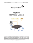

![TSP091 MCL PCI Card User Manual V1[1].](http://vs1.manualzilla.com/store/data/005724184_1-fb2316c3e25785c5ec1a95e56a29cba9-150x150.png)


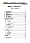


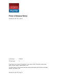
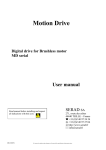


![TSP030 ccEuroTeach User Manual V1[1].4(2)](http://vs1.manualzilla.com/store/data/005682308_1-f9d13610d7f8864488377d3c706bdc7d-150x150.png)
