1
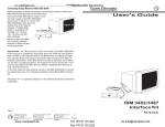
im Vertrieb von
CAMBOARD Electronics
User’s Manual
VS 200 SL
VideoShift with ShiftLock
EXTRON ELECTRONICS/RGB SYSTEMS, INC.
1230 South Lewis Street, Anaheim, CA 92805
800.633.9876 714.491.1500 FAX 714.491.1517
USA
EXTRON ELECTRONICS, EUROPE
Beeldschermweg 6C, 3821 AH Amersfoort
+31.33.453.4040 FAX +31.33.453.4050
The Netherlands
www.camboard.de
EXTRON ELECTRONICS, ASIA
41B Kreta Ayer Road, Singapore 089003
+65.226.0015 FAX +65.226.0019
Singapore
EXTRON ELECTRONIC INFORMATION
EXTRONWEB™: www.extron.com
EXTRONFAX™: 714.491.0192
24-hour access — worldwide!
Tel. 07131 911201
Fax 07131 911203
68-334 -01
Printed in the USA
[email protected]
im Vertrieb von
Precautions
Safety Instructions • English
This symbol is intended to alert the user of important
operating and maintenance (servicing) instructions
in the literature provided with the equipment.
This symbol is intended to alert the user of the
presence of uninsulated dangerous voltage within
the product's enclosure that may present a risk of
electric shock.
Caution
Read Instructions • Read and understand all safety and operating
instructions before using the equipment.
Retain Instructions • The safety instructions should be kept for future
reference.
Follow Warnings • Follow all warnings and instructions marked on the
equipment or in the user information.
Avoid Attachments • Do not use tools or attachments that are not
recommended by the equipment manufacturer because they may be
hazardous.
Consignes de Sécurité • Français
Ce symbole sert à avertir l’utilisateur que la
documentation fournie avec le matériel contient des
instructions importantes concernant l’exploitation
et la maintenance (réparation).
Ce symbole sert à avertir l’utilisateur de la présence
dans le boîtier de l’appareil de tensions dangereuses
non isolées posant des risques d’électrocution.
Attention
Lire les instructions• Prendre connaissance de toutes les consignes de
sécurité et d’exploitation avant d’utiliser le matériel.
Conserver les instructions• Ranger les consignes de sécurité afin de
pouvoir les consulter à l’avenir.
Respecter les avertissements • Observer tous les avertissements et
consignes marqués sur le matériel ou présentés dans la documentation
utilisateur.
Eviter les pièces de fixation • Ne pas utiliser de pièces de fixation ni
d’outils non recommandés par le fabricant du matériel car cela
risquerait de poser certains dangers.
Sicherheitsanleitungen • Deutsch
Dieses Symbol soll dem Benutzer in der im
Lieferumfang enthaltenen Dokumentation
besonders wichtige Hinweise zur Bedienung und
Wartung (Instandhaltung) geben.
Dieses Symbol soll den Benutzer darauf aufmerksam
machen, daß im Inneren des Gehäuses dieses
Produktes gefährliche Spannungen, die nicht isoliert
sind und die einen elektrischen Schock verursachen
können, herrschen.
Achtung
Lesen der Anleitungen • Bevor Sie das Gerät zum ersten Mal verwenden,
sollten Sie alle Sicherheits-und Bedienungsanleitungen genau
durchlesen und verstehen.
Aufbewahren der Anleitungen • Die Hinweise zur elektrischen Sicherheit
des Produktes sollten Sie aufbewahren, damit Sie im Bedarfsfall darauf
zurückgreifen können.
Befolgen der Warnhinweise • Befolgen Sie alle Warnhinweise und
Anleitungen auf dem Gerät oder in der Benutzerdokumentation.
Keine Zusatzgeräte • Verwenden Sie keine Werkzeuge oder Zusatzgeräte,
die nicht ausdrücklich vom Hersteller empfohlen wurden, da diese eine
Gefahrenquelle darstellen können.
Instrucciones de seguridad • Español
Este símbolo se utiliza para advertir al usuario sobre
instrucciones importantes de operación y
mantenimiento (o cambio de partes) que se desean
destacar en el contenido de la documentación
suministrada con los equipos.
Este símbolo se utiliza para advertir al usuario sobre
la presencia de elementos con voltaje peligroso sin
protección aislante, que puedan encontrarse dentro
de la caja o alojamiento del producto, y que puedan
representar riesgo de electrocución.
Precaucion
Leer las instrucciones • Leer y analizar todas las instrucciones de
operación y seguridad, antes de usar el equipo.
Conservar las instrucciones • Conservar las instrucciones de seguridad
para futura consulta.
Obedecer las advertencias • Todas las advertencias e instrucciones
marcadas en el equipo o en la documentación del usuario, deben ser
obedecidas.
Evitar el uso de accesorios • No usar herramientas o accesorios que no
sean especificamente recomendados por el fabricante, ya que podrian
implicar riesgos.
www.camboard.de
CAMBOARD Electronics
Extron’s Warranty
Warning
Power sources • This equipment should be operated only from the power source
indicated on the product. This equipment is intended to be used with a main
power system with a grounded (neutral) conductor. The third (grounding) pin is
a safety feature, do not attempt to bypass or disable it.
Power disconnection • To remove power from the equipment safely, remove all
power cords from the rear of the equipment, or the desktop power module (if
detachable), or from the power source receptacle (wall plug).
Power cord protection • Power cords should be routed so that they are not likely to
be stepped on or pinched by items placed upon or against them.
Servicing • Refer all servicing to qualified service personnel. There are no userserviceable parts inside. To prevent the risk of shock, do not attempt to service
this equipment yourself because opening or removing covers may expose you to
dangerous voltage or other hazards.
Slots and openings • If the equipment has slots or holes in the enclosure, these are
provided to prevent overheating of sensitive components inside. These openings
must never be blocked by other objects.
Lithium battery • There is a danger of explosion if battery is incorrectly replaced.
Replace it only with the same or equivalent type recommended by the
manufacturer. Dispose of used batteries according to the manufacturer's
instructions.
Avertissement
Alimentations• Ne faire fonctionner ce matériel qu’avec la source d’alimentation
indiquée sur l’appareil. Ce matériel doit être utilisé avec une alimentation
principale comportant un fil de terre (neutre). Le troisième contact (de mise à la
terre) constitue un dispositif de sécurité : n’essayez pas de la contourner ni de la
désactiver.
Déconnexion de l’alimentation• Pour mettre le matériel hors tension sans danger,
déconnectez tous les cordons d’alimentation de l’arrière de l’appareil ou du
module d’alimentation de bureau (s’il est amovible) ou encore de la prise secteur.
Protection du cordon d’alimentation • Acheminer les cordons d’alimentation de
manière à ce que personne ne risque de marcher dessus et à ce qu’ils ne soient pas
écrasés ou pincés par des objets.
Réparation-maintenance • Faire exécuter toutes les interventions de réparationmaintenance par un technicien qualifié. Aucun des éléments internes ne peut être
réparé par l’utilisateur. Afin d’éviter tout danger d’électrocution, l’utilisateur ne
doit pas essayer de procéder lui-même à ces opérations car l’ouverture ou le
retrait des couvercles risquent de l’exposer à de hautes tensions et autres dangers.
Fentes et orifices • Si le boîtier de l’appareil comporte des fentes ou des orifices,
ceux-ci servent à empêcher les composants internes sensibles de surchauffer. Ces
ouvertures ne doivent jamais être bloquées par des objets.
Lithium Batterie • Il a danger d'explosion s'll y a remplacment incorrect de la
batterie. Remplacer uniquement avec une batterie du meme type ou d'un ype
equivalent recommande par le constructeur. Mettre au reut les batteries usagees
conformement aux instructions du fabricant.
Vorsicht
Stromquellen • Dieses Gerät sollte nur über die auf dem Produkt angegebene
Stromquelle betrieben werden. Dieses Gerät wurde für eine Verwendung mit
einer Hauptstromleitung mit einem geerdeten (neutralen) Leiter konzipiert. Der
dritte Kontakt ist für einen Erdanschluß, und stellt eine Sicherheitsfunktion dar.
Diese sollte nicht umgangen oder außer Betrieb gesetzt werden.
Stromunterbrechung • Um das Gerät auf sichere Weise vom Netz zu trennen,
sollten Sie alle Netzkabel aus der Rückseite des Gerätes, aus der externen
Stomversorgung (falls dies möglich ist) oder aus der Wandsteckdose ziehen.
Schutz des Netzkabels • Netzkabel sollten stets so verlegt werden, daß sie nicht
im Weg liegen und niemand darauf treten kann oder Objekte darauf- oder
unmittelbar dagegengestellt werden können.
Wartung • Alle Wartungsmaßnahmen sollten nur von qualifiziertem
Servicepersonal durchgeführt werden. Die internen Komponenten des Gerätes
sind wartungsfrei. Zur Vermeidung eines elektrischen Schocks versuchen Sie in
keinem Fall, dieses Gerät selbst öffnen, da beim Entfernen der Abdeckungen die
Gefahr eines elektrischen Schlags und/oder andere Gefahren bestehen.
Schlitze und Öffnungen • Wenn das Gerät Schlitze oder Löcher im Gehäuse
aufweist, dienen diese zur Vermeidung einer Überhitzung der empfindlichen
Teile im Inneren. Diese Öffnungen dürfen niemals von anderen Objekten
blockiert werden.
Litium-Batterie • Explosionsgefahr, falls die Batterie nicht richtig ersetzt wird.
Ersetzen Sie verbrauchte Batterien nur durch den gleichen oder einen
vergleichbaren Batterietyp, der auch vom Hersteller empfohlen wird. Entsorgen
Sie verbrauchte Batterien bitte gemäß den Herstelleranweisungen.
Extron Electronics warrants this product against defects in materials and
workmanship for a period of two years from the date of purchase. In the event of
malfunction during the warranty period attributable directly to faulty workmanship
and/or materials, Extron Electronics will, at its option, repair or replace said products
or components, to whatever extent it shall deem necessary to restore said product to
proper operating condition, provided that it is returned within the warranty period,
with proof of purchase and description of malfunction to:
USA, Canada, South
America, Central
America, and Asia:
Extron Electronics
1230 South Lewis Street
Anaheim, CA 92805, U.S.A.
Europe, Africa, and the
Middle East:
Extron Electronics, Europe
Beeldschermweg 6C
3821 AH Amersfoort
The Netherlands
This Limited Warranty does not apply if the fault has been caused by misuse,
improper handling care, electrical or mechanical abuse, abnormal operating conditions
or non-Extron authorized modification to the product.
If it has been determined that the product is defective, please call Extron and ask for an
Applications Engineer at (714) 491-1500 (USA), 31.33.453.4040 (Europe), or 65.226.0015
(Asia) to receive an RA# (Return Authorization number). This will begin the repair
process as quickly as possible.
Units must be returned insured, with shipping charges prepaid. If not insured, you
assume the risk of loss or damage during shipment. Returned units must include the
serial number and a description of the problem, as well as the name of the person to
contact in case there are any questions.
Extron Electronics makes no further warranties either expressed or implied with
respect to the product and its quality, performance, merchantability, or fitness for any
particular use. In no event will Extron Electronics be liable for direct, indirect, or
consequential damages resulting from any defect in this product even if Extron
Electronics has been advised of such damage.
Please note that laws vary from state to state and country to country, and that some
provisions of this warranty may not apply to you.
Advertencia
Alimentación eléctrica • Este equipo debe conectarse únicamente a la fuente/tipo
de alimentación eléctrica indicada en el mismo. La alimentación eléctrica de este
equipo debe provenir de un sistema de distribución general con conductor
neutro a tierra. La tercera pata (puesta a tierra) es una medida de seguridad, no
puentearia ni eliminaria.
Desconexión de alimentación eléctrica • Para desconectar con seguridad la
acometida de alimentación eléctrica al equipo, desenchufar todos los cables de
alimentación en el panel trasero del equipo, o desenchufar el módulo de
alimentación (si fuera independiente), o desenchufar el cable del receptáculo de
la pared.
Protección del cables de alimentación • Los cables de alimentación eléctrica se
deben instalar en lugares donde no sean pisados ni apretados por objetos que se
puedan apoyar sobre ellos.
Reparaciones/mantenimiento • Solicitar siempre los servicios técnicos de personal
calificado. En el interior no hay partes a las que el usuario deba acceder. Para
evitar riesgo de electrocución, no intentar personalmente la reparación/
mantenimiento de este equipo, ya que al abrir o extraer las tapas puede quedar
expuesto a voltajes peligrosos u otros riesgos.
Ranuras y aberturas • Si el equipo posee ranuras o orificios en su caja/alojamiento,
es para evitar el sobrecalientamiento de componentes internos sensibles. Estas
aberturas nunca se deben obstruir con otros objetos.
Batería de litio • Existe riesgo de explosión si esta batería se coloca en la posición
incorrecta. Cambiar esta batería únicamente con el mismo tipo (o su equivalente)
recomendado por el fabricante. Desachar las baterías usadas siguiendo las
instrucciones del fabricante.
Tel. 07131 911201
Fax 07131 911203
[email protected]
im Vertrieb von
Contents
CAMBOARD Electronics
Terms that relate to this manual ...................................................... ii
Chapter 1 – Introduction
Description of VideoShift .............................................................
Screen Savers vs VideoShift ................................................
Applications ..........................................................................
Extron's VideoShift Products ................................................
Features ......................................................................................
VideoShift .............................................................................
Specifications ..............................................................................
1-1
1-1
1-1
1-1
1-2
1-2
1-2
Chapter 2 – Installation (Rear Panel)
Rear Panel Operation .................................................................
DIP Switch Settings ..............................................................
Automatic Sync Output Detection ........................................
ShiftLock ..............................................................................
Making ShiftLock Cables .............................................................
Mounting the VS 200 SL on a 1U Rack Shelf .............................
2-1
2-1
2-1
2-2
2-3
2-4
Chapter 3 – Operation
Front Panel Operation ................................................................. 3-1
Using a VS 200 SL with an Interface ........................................... 3-2
Legend of Icons
The following icons may be used in this manual:
___ Important information – for example, an action or a step that must
be done before proceeding.
___ A Warning – possible dangerous voltage present.
___ A Warning – possible damage could occur.
_ A Note, a Hint, or a Tip that may be helpful.
__ Additional information to help clarify the current subject.
VS 200 SL User's Manual
68-334-01
Rev. B
05 00
www.camboard.de
Tel. 07131 911201
Extron •
Fax 07131 911203
VS 200 SL • User’s Manual
[email protected]
i
im Vertrieb von
CAMBOARD Electronics
VS 200 SL User's Manual
Background Information
__ Terms that relate to this manual
Burn/Burn-in – Overexposure - In the case of CRTs, when the screen's
phosphor has been exposed to the electron beam for too long a
time, the phosphor becomes permanently damaged. The
damaged phosphor has a different color; that's why the image
appears to remain on the screen when the beam is off.
CRT (cathode ray tube) – Sometimes called a "picture tube", a CRT is a
vacuum tube that produces light when energized by the electron
beam inside the tube. The light beam strikes a phosphor coating
on the back side of the screen, causing it to glow.
Phosphor – The chemical coating on the inside of a CRT screen that emits
light when struck by the electron scan beam.
Light
output
Electron beam
Phosphor
screen
1
Chapter One
Introduction
Description of VideoShift
Screen Saver – Any method of "saving" the CRT screen from phosphor burn
by changing the displayed image or by blanking the screen.
Example of Phosphor Burn
If the text on the top screen were to stay
too long, it could damage the phosphor
on the screen.
As shown on the second screen, when
the text does change, there are images
of the old text burned into the phosphor,
making it difficult to read the new text.
ii
www.camboard.de
Tel. 07131 911201
Extron •
Fax 07131 911203
Extron • VS 200 SL • User’s Manual
Features
Specifications
VS 200 SL • User’s Manual
[email protected]
im Vertrieb von
Description and Features
CAMBOARD Electronics
Description and Features
Description of VideoShift
Features
VideoShiftTM is a video image movement system designed to
extend the life of projection CRTs in large screen projectors and
data monitors. The VideoShift system moves, or shifts, the video
image clockwise around the display screen area. This movement
is so gradual that it takes several minutes for each rotation, and it
is not noticeable by viewers. Shifting the image limits the time
during which bright video information remains in one spot on the
CRT phosphor. Moving the image allows the phosphor to cool
down and recover, thus extending its life.
•
•
•
•
•
•
VideoShift
VideoShift movement is to the
right, and then down, to the left,
and then up, etc. This is
illustrated to the right. The
distance of the shift or
movement depends upon the
range setting.
Screen Savers vs VideoShift
Ordinarily, the life of a CRT or monitor is shortened by allowing
intense or bright information to be displayed in the same location
of the CRT screen for an extended period of time. Images “burn”
into the screen, causing discoloration of the phosphor. Burned
phosphor also has less brightness. This is why computers use
screen saver programs. However, there are applications where a
screen saver would not be practical because the information must
remain on the screen. One example where this is necessary is on
the flight schedule monitors at an airport. The information is
usually stationary white text on a black background. Because
much of the information does not often change, the intense white
text will burn or discolor the display. When the display is turned
off, or the information changes, evidence of old information can
still be seen – usually a dull, brown image.
The vertical shift is in number of
lines, while the horizontal shift is
in units of time. Approximate
settings are:
Minimum setting:
Vertical shift = 8 scan lines
(4 up and 4 down from center)
Horizontal shift = 0.1 µsec.
Mid-range setting:
Vertical shift = 16 scan lines
Horizontal shift = 0.68 µsec.
Applications
A VideoShift system gets the best results when graphic images
are made up of text or lines, because the bright areas are small or
narrow. However, graphic images that have large, bright areas are
less successful because the images are too large to move to a
new area (i.e., when a large, bright area is shifted, it may overlap
the area it previously occupied). However, the VideoShift system
can limit the amount of phosphor burn by distributing the intensity
over a larger area, making it less noticeable.
_ We could think of the phosphor on a screen as being like a field of
grass. Walking across the field occasionally, or in a random
pattern, allows the grass to recover and there is no noticeable path.
However, walking frequently across the same area will wear a path
because the grass can't grow back.
This manual covers the VS 200 SL, one of Extron’s products that
uses VideoShift to prevent burn-in by moving the displayed image
around on the screen. The VS 200 SL model also uses Extron's
ShiftLock™ feature, which allows several ShiftLock devices to be
digitally locked in a master/slave VideoShift system. The master
unit supplies the VideoShift sequence for each slave.
www.camboard.de
Maximum setting:
Vertical shift = 32 scan lines
Horizontal shift = 1.28 µsec.
The actual horizontal distance
depends on the video format.
__ Here are two examples at
maximum range:
SGI – 128 pixels
VGA3 (640 x 480, 31.5 kHz)
– 64 pixels
Specifications
Video input
Extron's VideoShift Products
1-1
Metal enclosure that is half the width of a rack, and 1U high.
Auto-switchable 100-240 VAC, 50/60 Hz power supply.
Input capability of RGBS or RGBHV signals.
Outputs RGBS or RGBHV to the connected projector.
Digital sync processing, making the movement imperceptible.
Includes ShiftLock.
Number/type ..............................
Connectors ................................
Nominal level(s) .........................
Impedance .................................
Horizontal frequency .................
Vertical frequency ......................
Return loss ................................
Tel. 07131 911201
Extron •
Fax 07131 911203
Extron • VS 200 SL • User’s Manual
VS 200 SL • User’s Manual
1 RGBHV, RGBS, RGsB
5 BNC female
Analog ....... 0.3V to 1.25V p-p
75 ohms (all inputs are terminated at 75 ohms)
15 kHz to 150 kHz
40 Hz to 140 Hz
-30dB @ 5 MHz
[email protected]
1-2
im Vertrieb von
CAMBOARD Electronics
VS 200 SL User's Manual
Specifications
Video throughput
Gain ...........................................
Bandwidth ..................................
Rise time ...................................
Frequency response ..................
Crosstalk ...................................
Unity
250 MHz (-3dB), fully loaded
1.6 bS
< ± 0.1dB to 15 MHz
-6dB @ 3.58 MHz
Video characteristics
Unit-to-unit tracking (ShiftLock) .. Between units .......... ± 0.5 nS accuracy
Long-term drift ......... ± 0.5 nS accuracy
< 0.1 pixels @ 60 kHz
< 0.05 pixels @ 31.5 kHz
Video output
Number/type/format ...................
Connectors ................................
Nominal level .............................
Impedance .................................
Return loss ................................
DC offset ...................................
1 RGBHV, RGBS, RGsB
5 BNC female
1V p-p
75 ohms
-30dB @ 5 MHz
± 5mV maximum
Sync
Input type ...................................
Output type ................................
ShoftLock connectors ................
Input level ..................................
Output level ...............................
Input impedance ........................
Output impedance .....................
Output level ...............................
Max. rise/fall time ......................
Polarity ......................................
RGBHV, RGBS, RGsB
RGBHV, RGBS, RGsB
2 female jacks (ShiftLock)
TTL ............ 0.5V to 5V p-p
TTL ............ 4V to 5V p-p
510 ohms
75 ohms
4V to 5V p-p
4.15 nS
Positive/negative
Installation
General
Power ........................................ 100VAC to 240VAC, 50/60 Hz, 12 watts,
internal, autoswitchable
Temperature/humidity ............... Storage -40° to 158°F (-40° ro +70°C) / 10%
to 90%, non-condensing
Operating +32° to +122°F (0° to +50°C) /
10% to 90%, non-condensing
Rack mount ............................... Yes, with optional 1U rack shelf, part #60190-01
Enclosure type ........................... Metal
Enclosure dimensions ............... 1.75”H x 8.75” W x 9.50” D
4.45 c mH x 22.2 xcm W x 24.13 cm D
Sjipping weight .......................... 5 lbs (2.3 kg)
Vibration .................................... NSTA 1A in carton (National Safe Transit
Association)
Approvals .................................. CE
MTBF ......................................... 30,000 hours
Warranty .................................... 2 years parts and labor
Specifications are subject to change without notice.
1-3
www.camboard.de
2
Chapter Two
Tel. 07131 911201
Extron •
Fax 07131 911203
Extron • VS 200 SL • User’s Manual
Rear Panel Operation
Making ShiftLock Cables
Mounting the VS 200 SL in a Rack
VS 200 SL • User’s Manual
[email protected]
im Vertrieb von
ShiftLock Operation
CAMBOARD Electronics
Operation
Rear Panel Operation
ShiftLock
Following is the operation of VS 200 SL switches and connectors.
BNC Connectors – Connect Hi-Res BNC cables per application
requirements. See "Automatic Sync Output Detection" below.
ShiftLock In/Out Connectors – Allows connection of more than
one VS 200 SL to synchronize shifting. Use 2-conductor cables to
daisy-chain ShiftLock control between master and slave devices.
Set up ShiftLock only on the master; slaves shift with the master.
See pages 2-2 and 2-3.
DIP Switch Settings
The VS 200 SL has auto sync, which means it outputs sync
according to the impedance detected on the output cables.
However, the DIP switch settings take priority. If a switch is set, it
forces a condition, regardless of what is detected.
The ShiftLock feature allows two or more VS 200 SL units to be
linked together so that all the units shift together. A toggle switch
on the front panel allows one unit to be set as the master. Each of
any other units connected must be set as a slave. The shift signal
goes from the master to all slaves. The ShiftLock controls on the
front panel are described in chapter 3.
_ When the switch is set to Slave, the VideoShift
controls for that unit are disabled.
IN
OUT
Two connectors on the back panel are for the
master-slave interconnecting cables. Extron
provides the cable connectors. See page 2-3
for instructions on making the cables.
Setup example:
Following are the DIP switch settings for the VS 200 SL. In the
default positions (all switches OFF), sync output is determined by
the impedance detected through the output cables.
1. The master unit has a cable connected from its ShiftLock Out
port to the ShiftLock In port of the first slave. Its toggle switch
must be set to the Master position.
Sw#
1
2. The first slave has a cable from its ShiftLock Out port to the
ShiftLock In port of the next slave. Its toggle switch must be set
to the Slave position.
2
3
4
Position
ON
OFF-normal
ON
OFF-normal
ON
OFF-normal
ON
OFF-normal
5
Function
Always separate H and V sync
Automatic sync output detection
Always negative sync
Sync output polarity follows Input
No serration pulses
Serration pulses pass through.
(or added if not already present)
Vertical sync width = 2-3 times normal
Vertical sync width = normal
Not used
3. Repeat step #2 for each slave unit, except that the last slave (or
the only slave), will have no cable in its ShiftLock Out port.
IN
OUT
IN
OUT
IN
OUT
IN
OUT
Automatic Sync Output Detection
Sync is output in one of two ways, depending on the impedance
detected through the output cables:
Impedance = 75 ohm on R, G, and B,
or up to 1 kohm on sync lines.
Cabling Examples:
• Impedance on only R, G, B, & H/HV channels,
output = composite sync.
• Impedance on R, G, B, H/HV & V channels
output = separate H & V sync.
__ Turning a DIP switch ON overrides automatic
sync detection.
2-1
www.camboard.de
Tel. 07131 911201
Extron •
Fax 07131 911203
Extron • VS 200 SL • User’s Manual
VS 200 SL • User’s Manual
[email protected]
2-2
im Vertrieb von
Rack Mounting
CAMBOARD Electronics
ShiftLock Cables
Making ShiftLock Cables
Mounting the VS 200 SL on a 1U Rack Shelf
Extron supplies connectors for making ShiftLock cables; the user
supplies the cable. Twisted pair cable can be used – up to 50 feet
in length.
A 1U rack shelf accommodates two units the size of a VS 200 SL.
Each of these devices has two threaded holes in its base plate for
shelf-mounting.
The illustration below shows the steps for a making a cable using
twisted pair. Do each step for both ends of the cable. Make as
many cables as required.
1. If the VS 200 SL has feet, remove them.
2. Align the VS 200 SL over the shelf so that its two threaded holes
line up with two of the holes in the 1U shelf.
___ Although the color of the wire is not important, you must keep the
same wire color assignments for both ends of the cable.
3. Use two 4-40 x 1/8" screws
to mount the VS 200 SL to
the 1U shelf.
1. Unscrew the metal case.
2. Identify the contacts, parts, and connections.
Wire
Flex-Spring
___ The plastic insulator must be inside to prevent electrical contact
with the metal case.
As shown here, the connectors have three contacts. However,
only the “Tip” and “Ring” contacts are used.
VS 200 SL Rack Mount
3. Insert the metal case (insulator and flex spring) over the cable.
4. If the shelf is not already mounted in the rack, use the supplied
hardware and follow the instructions that came with the
1U Shelf (p/n 60-190-01).
5. When the VS 200 SL is mounted, continue the installation by
connecting the input, output, and power cables.
4. Strip the wires and attach them
through the holes in the contacts.
5. Solder both connections.
6. Bend the tabs around the cable
jacket.
7. Press the wires and contacts
inward to allow the Insulator
and metal case to slide over
easily.
___ Do not allow the contacts to
touch each other.
8
8. Screw the metal case
onto the connector.
VS 200 SL
Connection Diagram
Connect the cables according to the example on page 2-2.
2-3
www.camboard.de
Tel. 07131 911201
Extron •
Fax 07131 911203
Extron • VS 200 SL • User’s Manual
VS 200 SL • User’s Manual
[email protected]
2-4
im Vertrieb von
CAMBOARD Electronics
VS 200 SL User's Manual
Notes
3
Chapter Three
Operation
Front Panel Operations
Using a VS 200 SL with an Interface
2-5
www.camboard.de
Tel. 07131 911201
Extron •
Fax 07131 911203
Extron • VS 200 SL • User’s Manual
VS 200 SL • User’s Manual
[email protected]
im Vertrieb von
Connecting to Extron Interfaces
CAMBOARD Electronics
Operation
Front Panel Operation
Using a VS 200 SL with an Interface
Following are some instructions for using a VS 200 SL with Extron
interfaces.
Power LED
Indicates that the VS 200 SL is receiving power.
Shift Switch
Up = VideoShift is ON
Down = VideoShift is OFF.
Mode Switch
Up = Normal
Down = Test Mode
Used with the shift range knob (below). In test mode, the video
shifting is fast enough to be seen. This allows the range to be
adjusted while it is visible on the screen. Also use test mode for
setting horizontal and vertical centering, blanking, and sizing on
the projector.
ShiftLock/Master/Slave
Up = This is a master unit
Down = This is a slave unit.
___ Set the first unit as master; set others as slaves. See pages 2-2
and 2-3 for rear panel and ShiftLock cables.
xi Series interfaces – On this interface, DIP switch #1,
With RGB 202xi
on rear panel, must be ON. See the RGB 202xi User's Manual,
page 3-4 (Use LCD Sync processing).
With other interfaces – Set the interface DIP switches to remove
serrations.
If using separate H and V sync, turn off vertical shift (centering).
Centering Knobs
Vertical Shift ( )
Moves image up or down on the display screen.
Horizontal Shift (
)
Moves image left or right on the display screen.
Shift Range Knob
Use this in test mode to adjust the VideoShift range of movement.
Actual distance of range depends of the type of display being
used. (See page 1-2 for range settings.)
___ When finished with the ShiftLock, centering, sizing and blanking
setup, set the mode switch to Normal.
3-1
www.camboard.de
Tel. 07131 911201
Extron •
Fax 07131 911203
Extron • VS 200 SL • User’s Manual
VS 200 SL • User’s Manual
[email protected]
3-2
im Vertrieb von
3-3
www.camboard.de
CAMBOARD Electronics
Notes
Tel. 07131 911201
Fax 07131 911203
Extron • VS 200 SL • User’s Manual
[email protected]