1
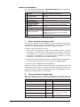
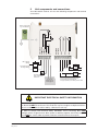
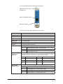
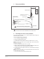
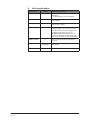
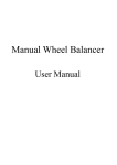
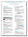
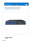
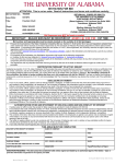
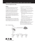
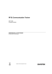
WIO-800LR wireless I/O receiver unit Quick Start Guide QSG 800LR ABOUT THIS DOCUMENT This is the Quick Start Guide for the MTL WIO-800LR Wireless I/O Receiver Unit and contains the following sections: 1 2 3 4 5 6 Section Read this section if you want to … Basic steps for using your unit Factory default configuration Unit components Learn the basic steps for installing and using your unit. Understand how the transmitter sends information to the receiver. Understand the different parts of your unit. Antenna installation Resetting factory defaults Linking Tx and Rx units Learn how to install an antenna with your unit. 7 Safety information 8 Specifications Reset your unit to the original factory default settings. Link your units to work as a dedicated pair. Understand important safety information related to your unit. NOTE: You must read this information before installing your unit. See the technical information. For more information, see the following sections. 1 Basic steps for using your unit This document describes how to configure your unit using the default factory configuration that lets you easily setup your network as a simple send/receive network using a dedicated pair of transmitter and receiver units. The basic steps for using your unit are: 1. Connect the antenna power supply and transducer signals using the instructions in this document. Power supply and transducer connection is described in the section Unit components and connections. Antenna connection is described in the section Antenna installation. For more information, see the WIO-800L Installation Manual. 2. Reset the transmitter and receiver units to the factory default configurations. 3. Link the transmitter and receiver units to work as a dedicated pair. 4. Bench test your configuration before deploying. NOTE: You can also configure your network using a user-defined customised configuration that lets you set specific information about your network. For more information on setting a user-defined customised configuration, see the WIO-800L User Manual on the enclosed CD. 2 Factory default configuration When you configure the units using the configuration in this document, the inputs from the transmitter are sent to the outputs at the receiver as follows WIO-800LT(Transmitter) Sends WIO-800LR (Receiver) Digital Input 1 _ Digital Output 1 Digital Input 2 _ Digital Output 2 Analogue Setpoint _ Digital Output 3 Analogue input (4-20 mA) _ Analog output (4-20 mA) Thermocouple Input (Not used) 2 Setpoint Output (Local indication) Communication Failure (Comes on if no messages from WIO-800LT) System OK (On if system OK) System OK (On if system OK) QSG 800LR-1.8 May 2010 3 Unit components and connections Your WIO-800LR receiver unit has the following components and terminal connections: IMPORTANT ELECTRICAL SAFETY INFORMATION In order to comply with Electrical Safety Regulations, this module must be installed in an Electrical AND Fire enclosure. This enclosure may be a single or multiple enclosures. Access to the module is to be made by a Service Person only. In order to comply with Electrical Safety Standards, when connecting SELV AND voltages which are greater than SELV (30VAC or 60VDC) together, then Relay Output 2 must NOT be used in order to provide sufficient isolation between the outputs. QSG 800LR-1.8 May 2010 3 The front panel provides the following components: SMA antenna connector at top of unit RS232 configuration port RSSI push button The LEDs on the front panel indicate the unit status: LED Status Indicates None No power supply. OK Green Current status of the unit OK. OK Red Fault condition detected in unit. RX Flashes Receiving Message. CF ON Module Communication Failure Output is active. PG ON Configuration Cable Connected. D1, D2, D3 ON The Output LEDS (D1, D2, D3) light when the corresponding output is active. LEDs with RSSI Push Button Pressed D1 Relay output D1 is ON (i.e. contact closed). D2 Relay Output D2 is ON. D3 Relay Output D3 is ON. When you press the RSSI push button, the unit shows the signal strength by lighting the LEDs from the bottom to the top. Signal strength is the strength of the last message received that was addressed to this station. LED Signal Strength LED Signal Strength D1 Better than -85 dBm RX Better than -100 dBm D2 Better than -90 dBm CF Better than -105 dBm Better than -95 dBm PG Always on during RSSI test D3 Output LED flashing quickly 4 If an output is in communication failure, the corresponding LED flashes at 5 Hz. D1 Relay Output D1 is in communication failure. D2 Relay Output D2 is in communication failure. D3 Relay Output D3 is in communication failure. PG Analog output is in communications failure. QSG 800LR-1.8 May 2010 4 Antenna installation The antenna must be be installed above all local obstructions 5 Resetting your unit to factory defaults You must reset the receiver unit to factory defaults before linking the transmitter and receiver units. To reset the default factory configuration: 1. Press and hold the RSSI push button. 2. Power on the WIO-800LR receiver. 3. The WIO-800LR receiver flashes all LEDs at medium flash (i.e. 1.6 Hz). NOTE: If the LEDs do not flash, you must repeat steps 1 and 2 until the LEDs flash before continuing. 4. Release the RSSI push button within 5 seconds. 5. Within a further 60 seconds, press and hold the RSSI push button for 5 seconds (until the LEDs stop flashing) and then release. 6. The WIO-800LR receiver lights all LEDs for 2 seconds before returning to normal operation. NOTE: If the LEDs do not light, you must repeat the process from step 1 until the LEDs light before continuing. 7. You can now link the transmitter and receiver units. QSG 800LR-1.8 May 2010 5 6 Linking your transmitter and receiver units You must reset the transmitter unit to factory defaults (to disable encryption) before linking the transmitter and receiver units. For more information, see the WIO-800LT Transmitter Quick Start Guide. NOTE: You must complete the linking process in 60 seconds. To link the transmitter and receiver units: 1. Press and hold down the RSSI Pushbutton on the receiver. 2. Power on the receiver while holding down the RSSI Pushbutton 3. Release the RSSI Pushbutton as soon as the Receiver LEDS flash (within 5 seconds of powering the receiver). 4. The receiver will flash all LEDs for a maximum 60 seconds while it tries to link to the transmitter. 5. Power on the transmitter. The transmitter sends a special “Link” message to allow the receiver to recognise the transmitter. 6. When the units link, the receiver lights all LEDs for 2 seconds before returning to normal operation. NOTE: If the receiver LEDs continue flashing within the 60 seconds, the units are not linked and you should retry the linking process by powering the transmitter off and on again. If you exceed the 60 seconds, you must restart the linking process from step 1. You can now bench test your configuration before deploying. 7 Safety information Thank you for selecting the WIO-800LR receiver for your telemetry needs. We trust it will give you many years of valuable service. To ensure your WIO-800LR receiver enjoys a long life, double-check ALL your connections with the user’s manual before powering on the unit. WARNING: Incorrect termination of supply wires may cause internal damage and will void warranty. 6 QSG 800LR-1.8 May 2010 8 Unit specifications Input/output QSG 800LR-1.8 May 2010 Number Additional information Digital outputs 3 Voltage-free contacts rated at 250 VAC 1A, 30VDC 1A. 2 for digital inputs and 1 for setpoint. Status outputs 2 Separate System OK and communication failure output. Analog output 1 16-bit resolution, 0.1% accuracy, singleended source output. Power supply 1 9-30 VDC 0.25 Amp CSA certified Class 2 power supply. For use in Class 1 Div 2 hazardous areas, the power supply must be approved for Class 1 Div 2 use. WARNING: Explosion hazard - do not connect or disconnect while circuit is live unless area is known to be non-hazardous. Radio receiver 1 High sensitivity DFSK Fixed Frequency receiver. Frequency 868.525 MHz 869.875MHz Sensitivity -111 dBm Actual frequency range depends on Paired Transmitter. At PER 8%. 7 MTL Instruments Pty Limited 9 /12 Billabong Street Stafford Queensland 4053 Australia Tel: + 61 1300 308 374 Fax: + 61 1300 308 463 E-mail: [email protected] Cooper Crouse-Hinds Japan KK MT Building 3F 2-7-5 Shiba Daimon Minato-ku Tokyo Japan 105-0012 Tel: +81 (0)3 6430 3128 Fax: +81 (0)3 6430 3129 E-mail: [email protected] Cooper Electric (Shanghai) Co. Ltd. Room 2001, China Life Tower 16 Chao Yang Men Wai Street Chao Yang District, Beijing China 100020 Tel: + 86 10 5980 0288 Fax: + 86 10 8562 5725 E-mail: [email protected] Cooper Crouse-Hinds Korea 12F, Vision Tower 707-2 Yeoksam-dong, Gangnam-gu Seoul 135-080 South Korea Tel: +82 2 3484 6795 Fax: +82 2 3484 6778 MTL Instruments sarl Les Carrés du Parc 10 rue des Rosiéristes 69410 Champagne au Mont d’Or France Tel: +33 (0)4 78 64 98 32 Fax: +33 (0)4 78 35 79 41 E-mail: [email protected] MTL Instruments GmbH An der Gümpgesbrücke 17 D-41564 Kaarst Germany Tel: +49 (0)2131 718930 Fax: +49 (0)2131 7189333 E-mail: [email protected] MTL India No. 36, Nehru Street Off Old Mahabalipuram Road Sholinganallur Chennai - 600 119 India Tel: + 91 (0)44 24501660/24501857 Fax: + 91 (0)44 24501463 E-mail: [email protected] MTL Italia srl Via Cantù 11 I - 20092 Cinisello Balsamo MI Italy Tel: +39 (0)2 61802011 Fax: +39 (0)2 61294560 E-mail: [email protected] Group Internet home page http://www.mtl-inst.com/ Members of The MTL Instruments Group MTL Instruments BV MTL Instruments BV Terheijdenseweg 465 4825BK Breda The Netherlands Tel: +31(0)76 7505360 Fax: +31(0)76 7505370 E-mail: [email protected] Cooper Crouse-Hinds Pte Ltd. No.2 Serangoon North Avenue 5 #06-01 Fu Yu Building Singapore 554911 Tel: +65 6 487 7887 Fax: +65 6 487 7997 E-mail: [email protected] MTL Instruments Villa No. 4, Sector 2-17, Street 6 PO Box 53234, Abu Dhabi, UAE Tel: +971 2 446 6840 Fax: +971 2 446 6841 E-mail: [email protected] Measurement Technology Limited Great Marlings, Butterfield, Luton, Beds England LU2 8DL Tel: +44 (0)1582 723633 Fax: +44 (0)1582 422283 E-mail: [email protected] Cooper Crouse-Hinds MTL Inc 3413 N. Sam Houston Parkway W. Suite 210 Houston TX 77086 USA Tel: +1 281 571 8065 Fax: +1 281 571 8069 E-mail: [email protected]