1
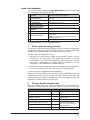
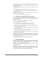
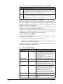
WIO-900LT wireless I/O transmitter unit Quick Start Guide QSG 900LT ABOUT THIS DOCUMENT This is the Quick Start Guide for the MTL WIO-900LT Wireless I/O Transmitter Unit and contains the following sections: 1 2 3 4 5 6 Section Read this section if you want to … Basic steps for using your unit Factory default configuration Unit components Learn the basic steps for installing and using your unit. Understand how the transmitter sends information to the receiver. Understand the different parts of your unit. Antenna installation Resetting factory defaults Linking Tx and Rx units Learn how to install an antenna with your unit. 7 Safety information 8 Specifications Reset your unit to the original factory default settings. Link your units to work as a dedicated pair. Understand important safety information related to your unit. NOTE: You must read this information before installing your unit. See the technical information. For more information, see the following sections. 1 Basic steps for using your unit This document describes how to configure your unit using the default factory configuration that lets you easily setup your network as a simple send/receive network using a dedicated pair of transmitter and receiver units. The basic steps for using your unit are: 1. Connect the antenna power supply and transducer signals using the instructions in this document. Power supply and transducer connection is described in the section Unit components and connections. Antenna connection is described in the section Antenna installation. For more information, see the WIO-900L Installation Manual. 2. Reset the transmitter and receiver units to the factory default configurations. 3. Link the transmitter and receiver units to work as a dedicated pair. 4. Bench test your configuration before deploying. NOTE: You can also configure your network using a user-defined customised configuration that lets you set specific information about your network. For more information on setting a user-defined customised configuration, see the WIO-900L User Manual on the enclosed CD. 2 Factory default configuration When you configure the units using the configuration in this document, the inputs from the transmitter are sent to the outputs at the receiver as follows WIO-900LT (Transmitter) Sends WIO-900LR (Receiver) Digital Input 1 _ Digital Output 1 Digital Input 2 _ Digital Output 2 Analogue Setpoint _ Digital Output 3 Analogue input (4-20 mA) _ Analog output (4-20 mA) Thermocouple Input (Not used) 2 Setpoint Output (Local indication) Communication Failure (Comes on if no messages from WIO-900LT) System OK (On if system OK) System OK (On if system OK) QSG 900LT-1.7 Oct 2010 3 Unit components and connections Your WIO-900LT transmitter unit has the following components and terminal connections: + + THERMOCOUPLE/mV COMMON AI DI 2 COMMON + DI 1 POWER SUPPLY ANALOG LOOP SUPPLY COMMON SP STATUS SYSTEM OK +24V + + + IMPORTANT ELECTRICAL SAFETY INFORMATION In order to comply with Electrical Safety Regulations, this module must be installed in an Electrical AND Fire enclosure. This enclosure may be a single or multiple enclosures. Access to the module is to be made by a Service Person only. QSG 900LT-1.7 Oct 2010 3 The front panel provides the following components: SMA antenna connector at top of unit RS232 configuration port Setpoint rotary switch The triangle on the rotary switch indicates the current position, for example: Position 0 or Position 3 NOTE: To avoid damaging the rotary switch, use a screwdriver to change the position. The rotary switch uses the following setpoint levels: Position 1 2 3 4 5 6 7 8 9 Lower level (mA) 4.8 6.4 8.0 9.6 11.2 12.8 14.4 16.0 17.6 Upper level (mA) 6.4 8.0 9.6 11.2 12.8 14.4 16.0 17.6 19.2 The LEDs on the front panel indicate the unit status: 4 LED Status Indicates None No power supply. OK Green Current status of the unit OK. OK Red Fault condition detected in unit. TX Flashes Transmitting Message. PG ON Configuration Cable Connected. QSG 900LT-1.7 Oct 2010 LED Status Indicates INPUTS ON The Input LEDS (D1, D2, SP, AZ) light when the corresponding input is active. All LEDs medium flash 4 D1 Digital Input 1 is active (Low). D2 Digital Input 2 is active SP Analogue setpoint is active AZ Analogue input is zero mA Medium speed flash (1.6HZ) indicates the module is half-way through the configuration process. Medium flash also happens when you set the rotary switch to position 0 when powering on the unit. Antenna installation The antenna must be be installed above all local obstructions 5 Resetting your unit to factory defaults You must reset the receiver unit to factory defaults before linking the transmitter and receiver units. To reset the default factory configuration: 1. Set the RSSI rotary switch to position 0 using a screwdriver. 2. Power on the WIO-900LT transmitter. QSG 900LT-1.7 Oct 2010 5 3. The WIO-900LT transmitter flashes all LEDs at medium flash (i.e. 1.6 Hz). NOTE: If the LEDs do not flash, you must repeat steps 1 and 2 until the LEDs flash before continuing. 4. Set the RSSI rotary switch to another position (e.g. position 1) within 5 seconds. 5. Set the RSSI rotary switch to position 0 within another 5 seconds. 6. The WIO-900LT transmitter lights all LEDs for 2 seconds before returning to normal operation. NOTE: If the LEDs do not light, you must repeat the process from step 1 until the LEDs light before continuing. 7. You can now link the transmitter and receiver units. 6 Linking your transmitter and receiver units You must reset the transmitter unit to factory defaults (to disable encryption) before linking the transmitter and receiver units. For more information, see the previous section. NOTE: You must complete the linking process in 60 seconds. To link the transmitter and receiver units: 1. Press and hold down the RSSI Pushbutton on the receiver. 2. Power on the receiver while holding down the RSSI Pushbutton 3. Release the RSSI Pushbutton as soon as the Receiver LEDS flash (within 5 seconds of powering the receiver). 4. The receiver will flash all LEDs for a maximum 60 seconds while it tries to link to the transmitter. 5. Power on the transmitter. The transmitter sends a special “Link” message to allow the receiver to recognise the transmitter. 6. When the units link, the receiver lights all LEDs for 2 seconds before returning to normal operation. NOTE: If the receiver LEDs continue flashing within the 60 seconds, the units are not linked and you should retry the linking process by powering the transmitter off and on again. If you exceed the 60 seconds, you must restart the linking process from step 1. You can now bench test your configuration before deploying. 7 Safety information Thank you for selecting the WIO-900LT transmitter for your telemetry needs. We trust it will give you many years of valuable service. To ensure your WIO-900LT transmitter enjoys a long life, double-check ALL your connections with the user’s manual before powering on the unit. WARNING: Incorrect termination of supply wires may cause internal damage and will void warranty. Exposure to RF energy is an important safety consideration. The FCC has adopted a safety standard for human exposure to radio frequency electromagnetic energy emitted by FCC regulated equipment as a result of its actions in Docket 93-62 and OET Bulletin 65 Edition 97-01. 6 QSG 900LT-1.7 Oct 2010 FCC Notice when used in USA: WIO-900LT Wireless I/O Module Part Additional information 15 This device has been tested and found to comply with the limits for a Class B digital device, pursuant to Part15 of the FCC rules (Code of Federal Regulations 47CFR Part 15). Operation is subject to the condition that this device does not cause harmful interference. 90 This device has been type accepted for operation by the FCC in accordance with Part90 of the FCC rules (47CFR Part 90). See the label on the unit for the specific FCC ID and any other certification designations. Industry Canada: WIO-900LT Wireless I/O Module RSS-119 - This device has been type accepted for operation by Industry Canada in accordance with RSS-119 of the Industry Canada rules. See the label on the unit for the specific Industry Canada certification number and any other certification designations. NOTE: Any changes or modifications not expressly approved by MTL could void the user’s authority to operate this equipment. To operate this equipment legally the user must obtain a radio-operating license from the government agency. This is done so the government can coordinate radio users in order to minimize interference. Safety information - FCC Notice This device complies with Part 15.247 of the FCC Rules. Operation is subject to the following two conditions: • This device may not cause harmful interference; and • This device must accept any interference received, including interference that may cause undesired operation NOTE: This equipment is suitable for use in Class 1 Division 2 groups A, B, C and D or non-hazardous locations only. 8 Unit specifications Input/output Number Digital inputs 2 Analog inputs 1 Thermocouple inputs 1 Power supply QSG 900LT-1.7 Oct 2010 1 Transmitter 1 Frequency 902 – 928 MHz Additional information Dry-contact digital inputs slow-pulsed at 10Hz. All inputs are suitable for voltage free contacts (e.g. mechanical switches) or NPN transistor devices (e.g. electronic proximity switches). NOTE: PNP transistor device inputs are NOT suitable. 0-20mA differential input; 16-bit resolution, 0.1% accuracy, 10 ohm input impedance. J, K or T type thermocouple with on-board cold-junction compensation. Cold junction compensation accuracy ±1º over ambient temp range: -40º to +60ºC. 9-30 VDC 1 Amp CSA certified Class 2 power supply. For use in Class 1 Div 2 hazardous areas, the power supply must be approved for Class 1 Div 2 use. WARNING: Explosion hazard - do not connect or disconnect while circuit is live unless area is known to be non-hazardous. 1 Watt Frequency Hopping Spread Spectrum (FHSS) Transmitter. Actual frequency range depends on country. 7 MTL Instruments Pty Limited 9 /12 Billabong Street Stafford Queensland 4053 Australia Tel: + 61 1300 308 374 Fax: + 61 1300 308 463 E-mail: [email protected] Cooper Crouse-Hinds Japan KK MT Building 3F 2-7-5 Shiba Daimon Minato-ku Tokyo Japan 105-0012 Tel: +81 (0)3 6430 3128 Fax: +81 (0)3 6430 3129 E-mail: [email protected] Cooper Electric (Shanghai) Co. Ltd. Room 2001, China Life Tower 16 Chao Yang Men Wai Street Chao Yang District, Beijing China 100020 Tel: + 86 10 5980 0288 Fax: + 86 10 8562 5725 E-mail: [email protected] Cooper Crouse-Hinds Korea 12F, Vision Tower 707-2 Yeoksam-dong, Gangnam-gu Seoul 135-080 South Korea Tel: +82 2 3484 6795 Fax: +82 2 3484 6778 MTL Instruments sarl Les Carrés du Parc 10 rue des Rosiéristes 69410 Champagne au Mont d’Or France Tel: +33 (0)4 78 64 98 32 Fax: +33 (0)4 78 35 79 41 E-mail: [email protected] MTL Instruments GmbH An der Gümpgesbrücke 17 D-41564 Kaarst Germany Tel: +49 (0)2131 718930 Fax: +49 (0)2131 7189333 E-mail: [email protected] MTL India No. 36, Nehru Street Off Old Mahabalipuram Road Sholinganallur Chennai - 600 119 India Tel: + 91 (0)44 24501660/24501857 Fax: + 91 (0)44 24501463 E-mail: [email protected] MTL Italia srl Via Cantù 11 I - 20092 Cinisello Balsamo MI Italy Tel: +39 (0)2 61802011 Fax: +39 (0)2 61294560 E-mail: [email protected] Group Internet home page http://www.mtl-inst.com/ Members of The MTL Instruments Group MTL Instruments BV MTL Instruments BV Terheijdenseweg 465 4825BK Breda The Netherlands Tel: +31(0)76 7505360 Fax: +31(0)76 7505370 E-mail: [email protected] Cooper Crouse-Hinds Pte Ltd. No.2 Serangoon North Avenue 5 #06-01 Fu Yu Building Singapore 554911 Tel: +65 6 487 7887 Fax: +65 6 487 7997 E-mail: [email protected] MTL Instruments Villa No. 4, Sector 2-17, Street 6 PO Box 53234, Abu Dhabi, UAE Tel: +971 2 446 6840 Fax: +971 2 446 6841 E-mail: [email protected] Measurement Technology Limited Great Marlings, Butterfield, Luton, Beds England LU2 8DL Tel: +44 (0)1582 723633 Fax: +44 (0)1582 422283 E-mail: [email protected] Cooper Crouse-Hinds MTL Inc 3413 N. Sam Houston Parkway W. Suite 210 Houston TX 77086 USA Tel: +1 281 571 8065 Fax: +1 281 571 8069 E-mail: [email protected]