1
Flow Sensor Connections
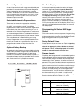
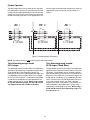
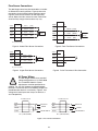
The 962 Stager control may be connected to a number
of different flow sensing devices. Figure 3 shows the
connections for the Autotrol turbine type flow sensor.
Figure 4 shows the connections for the Signet flow
sensor. Most of the flow sensors that are used will be
wired similarly, though the wire colors may vary.
GREEN
11
SHIELD
(BARE)
WHITE
12
GROUND
(WHITE)
BLACK
13
SIGNAL
(BLACK)
RED
14
+12VDC
(RED)
Turbine
Probe
GREEN
11
WHITE
12 GROUND (BLACK)
BLACK
13
SIGNAL
(GREEN)
RED
14
+12VDC
(RED)
Flow
Sensor
TB2 - (LOW VOLTAGE)
Figure 5 Fleck Flow Sensor Connections
Figure 3 Autotrol Flow Sensor Connections
GREEN
11
WHITE
12
SHIELD
(BARE)
BLACK
13
SIGNAL
(RED)
RED
14
+12VDC
(BLACK)
GREEN
Flow
Sensor
WHITE
12
BLACK
13
RED
TB2 - (LOW VOLTAGE)
Figure 6 Pulse Transmitter 2 Wire Connection
Figure 4 Signet Flow Sensor Connections
AC Power Wiring
The 962 Stager controls have standard
voltage configurations of 115 VAC 50/60
Hz, or 230 VAC 50/60 Hz. Power
requirements must be specified when
ordering. For 115 VAC jumpers are placed between
terminals 1 and 3 and 2 and 4. For 230VAC jumpers are
placed between terminals 2 and 3 only, Figure 5. Line
voltage and neutral inputs are always on terminals 1
and 4 respectively.
115 VAC 50/60 Hz
BLUE
4
RED
3
WHITE
2
BLACK
1
230 VAC 50/60 Hz
NEUTRAL IN
JUMPER
LINE VOLTAGE IN
TB1 - (HIGH VOLTAGE)
BLUE
4
RED
3
WHITE
2
BLACK
1
TB1 - (HIGH VOLTAGE)
Figure 7 AC Power Connections
16
NEUTRAL IN
JUMPER
LINE VOLTAGE IN