1
FACHHOCHSCHULE LANDSHUT
FACHBEREICH INFORMATIK
Development of a Linux
Driver for a MOST Interface
and Porting to RTAI
Diplomarbeit
Vorgelegt von:
Eingereicht am:
Betreuer FH:
Betreuer Siemens:
Bernhard Walle aus Neufahrn i. NB
15. September 2006
Prof. Dr. rer. nat. Peter Hartlmüller
Gernot Hillier, Siemens AG, CT SE 2
Erklärung zur Diplomarbeit
(gemäß § 31, Abs. 7 RaPO)
Name, Vorname des
Studierenden:
Bernhard Walle
Fachhochschule Landshut
Fachbereich Informatik
Hiermit erkläre ich, dass ich die Arbeit selbständig verfasst, noch nicht anderweitig für Prüfungszwecke vorgelegt, keine anderen als die angegebenen
Quellen oder Hilfsmittel benützt sowie wörtliche und sinngemäße Zitate als
solche gekennzeichnet habe.
15. 09. 2006
Datum
Unterschrift des Studierenden
Contents
1 Introduction
1.1 About the Topic of this Thesis . . .
1.2 Overview . . . . . . . . . . . . . .
1.3 Conventions . . . . . . . . . . . .
1.3.1 Terms . . . . . . . . . . . .
1.3.2 Units . . . . . . . . . . . .
1.3.3 Typographical Conventions
1.4 Source Code . . . . . . . . . . . .
1.4.1 Listings . . . . . . . . . . .
1.4.2 Original Software Code . .
1.4.3 MOST Driver and Utilities
.
.
.
.
.
.
.
.
.
.
.
.
.
.
.
.
.
.
.
.
.
.
.
.
.
.
.
.
.
.
.
.
.
.
.
.
.
.
.
.
.
.
.
.
.
.
.
.
.
.
.
.
.
.
.
.
.
.
.
.
.
.
.
.
.
.
.
.
.
.
.
.
.
.
.
.
.
.
.
.
.
.
.
.
.
.
.
.
.
.
.
.
.
.
.
.
.
.
.
.
.
.
.
.
.
.
.
.
.
.
.
.
.
.
.
.
.
.
.
.
.
.
.
.
.
.
.
.
.
.
.
.
.
.
.
.
.
.
.
.
.
.
.
.
.
.
.
.
.
.
19
19
20
20
20
21
21
21
21
22
22
2 Basics
2.1 Linux Device drivers . . . . . . . . . . . . . . . . . . . . .
2.1.1 Kernel Modules . . . . . . . . . . . . . . . . . . .
2.1.2 Device Files and System Calls . . . . . . . . . . . .
2.1.3 Linux Driver API . . . . . . . . . . . . . . . . . . .
2.1.4 The Proc FS and Other Virtual File Systems . . . .
2.1.5 Hardware Communication . . . . . . . . . . . . .
2.1.5.1 I/O Ports and I/O Memory . . . . . . . .
2.1.5.2 Interrupts . . . . . . . . . . . . . . . . .
2.1.6 PCI . . . . . . . . . . . . . . . . . . . . . . . . . .
2.1.6.1 PCI Configuration . . . . . . . . . . . .
2.1.6.2 The PCI Subsystem in Linux . . . . . . .
2.1.7 Managing Concurrency . . . . . . . . . . . . . . .
2.1.7.1 Contexts . . . . . . . . . . . . . . . . . .
2.1.7.2 Mechanisms . . . . . . . . . . . . . . . .
2.1.8 Timestamps . . . . . . . . . . . . . . . . . . . . .
2.1.8.1 Hardware Timers . . . . . . . . . . . . .
2.1.8.2 Linux Timekeeping Architecture . . . .
2.1.9 Softirqs . . . . . . . . . . . . . . . . . . . . . . . .
2.2 Real-time Operating Systems . . . . . . . . . . . . . . . .
2.2.1 Overview . . . . . . . . . . . . . . . . . . . . . . .
2.2.2 Real-time Linux . . . . . . . . . . . . . . . . . . .
2.2.2.1 Introduction . . . . . . . . . . . . . . .
2.2.2.2 Virtualisation Layers . . . . . . . . . . .
2.2.3 Real-time Applications with RTAI . . . . . . . . .
2.2.3.1 Kernelspace . . . . . . . . . . . . . . . .
2.2.3.2 Userspace . . . . . . . . . . . . . . . . .
2.2.3.3 Communication with Linux Applications
2.2.4 Xenomai . . . . . . . . . . . . . . . . . . . . . . .
.
.
.
.
.
.
.
.
.
.
.
.
.
.
.
.
.
.
.
.
.
.
.
.
.
.
.
.
.
.
.
.
.
.
.
.
.
.
.
.
.
.
.
.
.
.
.
.
.
.
.
.
.
.
.
.
.
.
.
.
.
.
.
.
.
.
.
.
.
.
.
.
.
.
.
.
.
.
.
.
.
.
.
.
.
.
.
.
.
.
.
.
.
.
.
.
.
.
.
.
.
.
.
.
.
.
.
.
.
.
.
.
.
.
.
.
.
.
.
.
.
.
.
.
.
.
.
.
.
.
.
.
.
.
.
.
.
.
.
.
.
.
.
.
.
.
.
.
.
.
.
.
.
.
.
.
.
.
.
.
.
.
.
.
.
.
.
.
.
.
.
.
.
.
.
.
.
.
.
.
.
.
.
.
.
.
.
.
.
.
.
.
.
.
.
.
.
.
.
.
.
.
.
.
.
.
.
.
.
.
.
.
.
.
.
.
.
.
.
.
.
.
.
.
.
.
.
.
.
.
.
.
.
.
.
.
.
.
.
.
.
.
.
.
.
.
.
.
.
.
.
.
.
.
.
.
.
.
.
.
.
.
.
.
.
.
.
.
.
.
.
.
.
.
.
.
.
.
.
.
.
.
.
.
.
.
.
.
.
.
.
.
.
.
.
.
.
.
.
.
.
.
.
.
.
.
.
.
.
.
.
.
.
.
.
.
.
.
.
.
.
.
.
.
.
.
.
.
.
.
.
.
.
.
.
.
.
.
.
.
.
.
.
.
.
.
.
.
.
.
.
.
.
.
.
.
.
.
.
.
.
.
.
.
.
.
.
.
.
.
.
.
.
.
.
.
.
.
.
.
.
.
.
.
.
.
.
.
.
.
.
.
23
23
23
25
25
26
26
26
27
28
28
28
30
30
31
32
32
32
34
35
35
36
36
36
38
38
40
40
42
.
.
.
.
.
.
.
.
.
.
.
.
.
.
.
.
.
.
.
.
.
.
.
.
.
.
.
.
.
.
.
.
.
.
.
.
.
.
.
.
.
.
.
.
.
.
.
.
.
.
.
.
.
.
.
.
.
.
.
.
.
.
.
.
.
.
.
.
.
.
.
.
.
.
.
.
.
.
.
.
.
.
.
.
.
.
.
.
.
.
.
.
.
.
.
.
.
.
.
.
.
.
.
.
.
.
.
.
.
.
.
.
.
.
.
.
.
.
.
.
5
2.2.5
2.3
Real-time Drivers . . . . . . . . . . . . . . . . . . .
2.2.5.1 Motivation . . . . . . . . . . . . . . . . .
2.2.5.2 Accessing Device Drivers from RTAI Tasks
2.2.5.3 Already Existing Real-Time Drivers . . . .
MOST . . . . . . . . . . . . . . . . . . . . . . . . . . . . . .
2.3.1 Overall Information . . . . . . . . . . . . . . . . . .
2.3.2 Data Transfer . . . . . . . . . . . . . . . . . . . . . .
2.3.2.1 Synchronous Data . . . . . . . . . . . . .
2.3.2.2 Control Data . . . . . . . . . . . . . . . .
2.3.2.3 Asynchronous Data . . . . . . . . . . . . .
2.3.3 System Architecture . . . . . . . . . . . . . . . . . .
2.3.3.1 Terms . . . . . . . . . . . . . . . . . . . .
2.3.3.2 Hardware . . . . . . . . . . . . . . . . . .
2.3.3.3 Software . . . . . . . . . . . . . . . . . . .
2.3.4 MOST PCI Board . . . . . . . . . . . . . . . . . . .
2.3.4.1 Overview . . . . . . . . . . . . . . . . . .
2.3.4.2 Data Flow . . . . . . . . . . . . . . . . . .
2.3.5 OptoLyzer . . . . . . . . . . . . . . . . . . . . . . .
2.3.6 Windows Software Architecture . . . . . . . . . . .
2.3.6.1 Control Messages . . . . . . . . . . . . . .
2.3.6.2 Synchronous and Asynchronous Data . . .
3 Requirements
3.1 Current Situation . . . . . . . . . . . . . .
3.1.1 Real-time Drivers . . . . . . . . .
3.1.2 MOST . . . . . . . . . . . . . . .
3.2 Functional Requirements . . . . . . . . .
3.2.1 Linux Driver . . . . . . . . . . . .
3.2.2 RTDM Driver . . . . . . . . . . .
3.2.3 Hardware . . . . . . . . . . . . . .
3.2.4 Sample Applications . . . . . . . .
3.3 Non-functional Requirements . . . . . . .
3.3.1 Data rates . . . . . . . . . . . . .
3.3.2 Relationship to PCI Timing . . . .
3.3.3 Calculation of Timing Constraints
3.3.4 Result . . . . . . . . . . . . . . . .
.
.
.
.
.
.
.
.
.
.
.
.
.
.
.
.
.
.
.
.
.
.
.
.
.
.
4 Linux Driver
4.1 Structure . . . . . . . . . . . . . . . . . . . .
4.1.1 Overview . . . . . . . . . . . . . . . .
4.1.2 Base driver . . . . . . . . . . . . . . .
4.1.3 Low and High Drivers . . . . . . . . .
4.1.3.1 Low Driver . . . . . . . . .
4.1.3.2 High Driver . . . . . . . . .
4.1.3.3 Driver Structures . . . . . .
4.1.4 MOST Device . . . . . . . . . . . . .
4.1.4.1 Managing the Device Count
4.2 MOST NetServices . . . . . . . . . . . . . . .
4.2.1 Introduction . . . . . . . . . . . . . .
6
.
.
.
.
.
.
.
.
.
.
.
.
.
.
.
.
.
.
.
.
.
.
.
.
.
.
.
.
.
.
.
.
.
.
.
.
.
.
.
.
.
.
.
.
.
.
.
.
.
.
.
.
.
.
.
.
.
.
.
.
.
.
.
.
.
.
.
.
.
.
.
.
.
.
.
.
.
.
.
.
.
.
.
.
.
.
.
.
.
.
.
.
.
.
.
.
.
.
.
.
.
.
.
.
.
.
.
.
.
.
.
.
.
.
.
.
.
.
.
.
.
.
.
.
.
.
.
.
.
.
.
.
.
.
.
.
.
.
.
.
.
.
.
.
.
.
.
.
.
.
.
.
.
.
.
.
.
.
.
.
.
.
.
.
.
.
.
.
.
.
.
.
.
.
.
.
.
.
.
.
.
.
.
.
.
.
.
.
.
.
.
.
.
.
.
.
.
.
.
.
.
.
.
.
.
.
.
.
.
.
.
.
.
.
.
.
.
.
.
.
.
.
.
.
.
.
.
.
.
.
.
.
.
.
.
.
.
.
.
.
.
.
.
.
.
.
.
.
.
.
.
.
.
.
.
.
.
.
.
.
.
.
.
.
.
.
.
.
.
.
.
.
.
.
.
.
.
.
.
.
.
.
.
.
.
.
.
.
.
.
.
.
.
.
.
.
.
.
.
.
.
.
.
.
.
.
.
.
.
.
.
.
.
.
.
.
.
.
.
.
.
.
.
.
.
.
.
.
.
.
.
.
.
.
.
.
.
.
.
.
.
.
.
.
.
.
.
.
.
.
.
.
.
.
.
.
.
.
.
.
.
.
.
.
.
.
.
.
.
.
.
.
.
.
.
.
.
.
.
.
.
.
.
.
.
.
.
.
.
.
.
.
.
.
.
.
.
.
.
.
.
.
.
.
.
.
.
.
.
.
.
.
.
.
.
.
.
.
.
.
.
.
.
.
.
.
.
.
.
.
.
.
.
.
.
.
.
.
.
.
.
.
.
.
.
.
.
.
.
.
.
.
.
.
.
.
.
.
.
.
.
.
.
.
.
43
43
43
44
45
45
46
46
46
47
48
48
48
49
50
50
50
52
53
53
54
.
.
.
.
.
.
.
.
.
.
.
.
.
.
.
.
.
.
.
.
.
.
.
.
.
.
.
.
.
.
.
.
.
.
.
.
.
.
.
.
.
.
.
.
.
.
.
.
.
.
.
.
.
.
.
.
.
.
.
.
.
.
.
.
.
.
.
.
.
.
.
.
.
.
.
.
.
.
.
.
.
.
.
.
.
.
.
.
.
.
.
.
.
.
.
.
.
.
.
.
.
.
.
.
.
.
.
.
.
.
.
.
.
.
.
.
.
.
.
.
.
.
.
.
.
.
.
.
.
.
.
.
.
.
.
.
.
.
.
.
.
.
.
.
.
.
.
.
.
.
.
.
.
.
.
.
.
.
.
.
.
.
.
.
.
.
.
.
.
55
55
55
56
56
56
56
57
57
57
57
58
59
59
.
.
.
.
.
.
.
.
.
.
.
61
61
61
61
62
62
63
64
64
66
67
67
.
.
.
.
.
.
.
.
.
.
.
.
.
.
.
.
.
.
.
.
.
.
.
.
.
.
.
.
.
.
.
.
.
.
.
.
.
.
.
.
.
.
.
.
.
.
.
.
.
.
.
.
.
.
.
.
.
.
.
.
.
.
.
.
.
.
.
.
.
.
.
.
.
.
.
.
.
.
.
.
.
.
.
.
.
.
.
.
.
.
.
.
.
.
.
.
.
.
.
.
.
.
.
.
.
.
.
.
.
.
.
.
.
.
.
.
.
.
.
.
.
.
.
.
.
.
.
.
.
.
.
.
Contents
4.2.2
4.2.3
4.3
Userspace vs. Kernelspace . . . . . . . . . . . .
The Kernel Module . . . . . . . . . . . . . . . .
4.2.3.1 General Description . . . . . . . . . .
4.2.3.2 Interrupt Processing . . . . . . . . . .
4.2.4 Userspace NetServices Implementation . . . . .
4.2.4.1 Device Access and Callback Functions
4.2.4.2 Initialisation and Deinitialisation . . .
4.2.4.3 Service Thread . . . . . . . . . . . . .
4.2.5 Sample Program for Control Messages . . . . . .
MOST Synchronous Driver . . . . . . . . . . . . . . . .
4.3.1 Access the Driver from Userspace . . . . . . . .
4.3.1.1 Configuring the Routing Engine . . . .
4.3.1.2 Configuring the Driver . . . . . . . . .
4.3.1.3 Reading and Writing Data . . . . . . .
4.3.2 MOST Synchronous Kernel Driver . . . . . . . .
4.3.2.1 Buffering of Data . . . . . . . . . . . .
4.3.2.2 Managing the Data Flow in the Driver .
4.3.2.3 Data Structures . . . . . . . . . . . . .
4.3.2.4 Synchronous Transmission . . . . . .
4.3.3 Sample Program for Synchronous Transfer . . .
4.3.4 PCI Bus Transfers . . . . . . . . . . . . . . . . .
4.3.4.1 Setting up the PCI Tracer . . . . . . . .
4.3.4.2 Transfers on the Bus . . . . . . . . . .
5 Porting to RTAI
5.1 Introduction . . . . . . . . . . . . . . . . . . . . . .
5.1.1 Overview . . . . . . . . . . . . . . . . . . . .
5.1.2 RTNRT Porting Framework . . . . . . . . . .
5.1.3 Error Handling . . . . . . . . . . . . . . . .
5.2 Real Time Driver Model (RTDM) . . . . . . . . . . .
5.2.1 Introduction . . . . . . . . . . . . . . . . . .
5.2.2 User API . . . . . . . . . . . . . . . . . . . .
5.2.2.1 Overview . . . . . . . . . . . . . .
5.2.2.2 Using the RTDM in an Example . .
5.2.2.3 Drawbacks . . . . . . . . . . . . .
5.2.3 Device Profiles . . . . . . . . . . . . . . . . .
5.2.4 Driver Development API . . . . . . . . . . .
5.2.5 API Versioning . . . . . . . . . . . . . . . . .
5.3 Structure of a Character Device Driver . . . . . . . .
5.3.1 Partitioning . . . . . . . . . . . . . . . . . .
5.3.2 Basic Structure of a Simple Driver . . . . . .
5.3.3 Registering a Character Device . . . . . . . .
5.3.4 The Device Context . . . . . . . . . . . . . .
5.3.5 Per-device Data . . . . . . . . . . . . . . . .
5.4 Porting Common Patterns Found in Drivers . . . . .
5.4.1 Resource Management and Memory Access .
5.4.2 Interrupt Handling . . . . . . . . . . . . . .
5.4.2.1 Registering an Interrupt Handler .
5.4.2.2 Deregistering an Interrupt Handler
Contents
.
.
.
.
.
.
.
.
.
.
.
.
.
.
.
.
.
.
.
.
.
.
.
.
.
.
.
.
.
.
.
.
.
.
.
.
.
.
.
.
.
.
.
.
.
.
.
.
.
.
.
.
.
.
.
.
.
.
.
.
.
.
.
.
.
.
.
.
.
.
.
.
.
.
.
.
.
.
.
.
.
.
.
.
.
.
.
.
.
.
.
.
.
.
.
.
.
.
.
.
.
.
.
.
.
.
.
.
.
.
.
.
.
.
.
.
.
.
.
.
.
.
.
.
.
.
.
.
.
.
.
.
.
.
.
.
.
.
.
.
.
.
.
.
.
.
.
.
.
.
.
.
.
.
.
.
.
.
.
.
.
.
.
.
.
.
.
.
.
.
.
.
.
.
.
.
.
.
.
.
.
.
.
.
.
.
.
.
.
.
.
.
.
.
.
.
.
.
.
.
.
.
.
.
.
.
.
.
.
.
.
.
.
.
.
.
.
.
.
.
.
.
.
.
.
.
.
.
.
.
.
.
.
.
.
.
.
.
.
.
.
.
.
.
.
.
.
.
.
.
.
.
.
.
.
.
.
.
.
.
.
.
.
.
.
.
.
.
.
.
.
.
.
.
.
.
.
.
.
.
.
.
.
.
.
.
.
.
.
.
.
.
.
.
.
.
.
.
.
.
.
.
.
.
.
.
.
.
.
.
.
.
.
.
.
.
.
.
.
.
.
.
.
.
.
.
.
.
.
.
.
.
.
.
.
.
.
.
.
.
.
.
.
.
.
.
.
.
.
.
.
.
.
.
.
.
.
.
.
.
.
.
.
.
.
.
.
.
.
.
.
.
.
.
.
.
.
.
.
.
.
.
.
.
.
.
.
.
.
.
.
.
.
67
68
68
69
71
71
72
72
73
75
75
75
76
77
77
78
79
79
80
81
81
82
82
.
.
.
.
.
.
.
.
.
.
.
.
.
.
.
.
.
.
.
.
.
.
.
.
.
.
.
.
.
.
.
.
.
.
.
.
.
.
.
.
.
.
.
.
.
.
.
.
.
.
.
.
.
.
.
.
.
.
.
.
.
.
.
.
.
.
.
.
.
.
.
.
.
.
.
.
.
.
.
.
.
.
.
.
.
.
.
.
.
.
.
.
.
.
.
.
.
.
.
.
.
.
.
.
.
.
.
.
.
.
.
.
.
.
.
.
.
.
.
.
.
.
.
.
.
.
.
.
.
.
.
.
.
.
.
.
.
.
.
.
.
.
.
.
.
.
.
.
.
.
.
.
.
.
.
.
.
.
.
.
.
.
.
.
.
.
.
.
.
.
.
.
.
.
.
.
.
.
.
.
.
.
.
.
.
.
.
.
.
.
.
.
.
.
.
.
.
.
.
.
.
.
.
.
.
.
.
.
.
.
.
.
.
.
.
.
.
.
.
.
.
.
.
.
.
.
.
.
.
.
.
.
.
.
.
.
.
.
.
.
.
.
.
.
.
.
.
.
.
.
.
.
.
.
.
.
.
.
.
.
.
.
.
.
.
.
.
.
.
.
.
.
.
.
.
.
.
.
.
.
.
.
.
.
.
.
.
.
.
.
.
.
.
.
.
.
.
.
.
.
.
.
.
.
.
.
.
.
.
.
.
.
.
.
.
.
.
.
.
.
.
.
.
.
.
.
.
.
.
.
.
.
.
.
.
.
.
.
.
.
.
.
.
.
.
.
.
.
.
.
.
.
.
.
.
.
.
.
.
.
85
85
85
85
86
86
86
87
87
87
88
89
89
90
90
90
91
91
93
93
94
94
94
94
95
7
5.5
5.4.2.3 Sharing Interrupts Between RTAI and Linux .
5.4.2.4 Return Value of the Interrupt Handler . . . .
5.4.2.5 Using the RTNRT Framework . . . . . . . . .
5.4.3 Synchronisation . . . . . . . . . . . . . . . . . . . . . .
5.4.3.1 Contexts . . . . . . . . . . . . . . . . . . . . .
5.4.3.2 Spinlocks . . . . . . . . . . . . . . . . . . . .
5.4.3.3 Semaphores and Mutexes . . . . . . . . . . .
5.4.3.4 Wait Queues . . . . . . . . . . . . . . . . . .
5.4.3.5 Sequence Locks . . . . . . . . . . . . . . . . .
5.4.4 Allocating Memory . . . . . . . . . . . . . . . . . . . .
5.4.5 Copying From and To Userspace . . . . . . . . . . . . .
5.4.5.1 Basics . . . . . . . . . . . . . . . . . . . . . .
5.4.5.2 Using the Functions in the RTNRT Framework
5.4.6 Kernel Threads . . . . . . . . . . . . . . . . . . . . . .
5.4.6.1 Linux Kernel Threads . . . . . . . . . . . . .
5.4.6.2 Real-time Task . . . . . . . . . . . . . . . . .
5.4.7 Time Stamps . . . . . . . . . . . . . . . . . . . . . . . .
5.4.7.1 Using Linux Services from Real-time Context
5.4.7.2 RTDM Time Functions . . . . . . . . . . . . .
5.4.7.3 RTNRT Framework . . . . . . . . . . . . . . .
5.4.8 Delaying Execution . . . . . . . . . . . . . . . . . . . .
5.4.8.1 Introduction . . . . . . . . . . . . . . . . . .
5.4.8.2 Sleeping . . . . . . . . . . . . . . . . . . . . .
5.4.8.3 Busy Waiting . . . . . . . . . . . . . . . . . .
5.4.8.4 Timeout . . . . . . . . . . . . . . . . . . . . .
5.4.9 Timers and Tasklets . . . . . . . . . . . . . . . . . . . .
5.4.9.1 Using RTDM Tasks . . . . . . . . . . . . . . .
5.4.9.2 Simple Native Timers . . . . . . . . . . . . . .
5.4.10 Linked Lists . . . . . . . . . . . . . . . . . . . . . . . .
Debugging . . . . . . . . . . . . . . . . . . . . . . . . . . . . .
5.5.1 Kernel Ring Buffer . . . . . . . . . . . . . . . . . . . . .
5.5.1.1 printk() and rtdm_printk() . . . . . . . . .
5.5.1.2 RTNRT Framework . . . . . . . . . . . . . . .
5.5.2 Serial Debuggers . . . . . . . . . . . . . . . . . . . . . .
6 RTAI Driver for MOST
6.1 What Must be Real-time? . . . . . . . . . . . . . . . . . . .
6.2 Changes in Existing Modules . . . . . . . . . . . . . . . . .
6.2.1 Base Driver . . . . . . . . . . . . . . . . . . . . . . .
6.2.1.1 Locking . . . . . . . . . . . . . . . . . . .
6.2.1.2 Adaptations in the MOST Device Structure
6.2.2 PCI Driver . . . . . . . . . . . . . . . . . . . . . . .
6.2.3 NetServices Driver . . . . . . . . . . . . . . . . . . .
6.2.4 Printing Messages . . . . . . . . . . . . . . . . . . .
6.3 Synchronous Module for Real-Time . . . . . . . . . . . . . .
6.3.1 MOST Synchronous Device Profile . . . . . . . . . .
6.3.1.1 Naming . . . . . . . . . . . . . . . . . . .
6.3.1.2 Device Methods . . . . . . . . . . . . . . .
6.3.1.3 Subclasses . . . . . . . . . . . . . . . . . .
8
.
.
.
.
.
.
.
.
.
.
.
.
.
.
.
.
.
.
.
.
.
.
.
.
.
.
.
.
.
.
.
.
.
.
.
.
.
.
.
.
.
.
.
.
.
.
.
.
.
.
.
.
.
.
.
.
.
.
.
.
.
.
.
.
.
.
.
.
.
.
.
.
.
.
.
.
.
.
.
.
.
.
.
.
.
.
.
.
.
.
.
.
.
.
.
.
.
.
.
.
.
.
.
.
.
.
.
.
.
.
.
.
.
.
.
.
.
.
.
.
.
.
.
.
.
.
.
.
.
.
.
.
.
.
.
.
.
.
.
.
.
.
.
.
.
.
.
.
.
.
.
.
.
.
.
.
.
.
.
.
.
.
.
.
.
.
.
.
.
.
.
.
.
.
.
.
.
.
.
.
.
.
.
.
.
.
.
.
.
.
.
.
.
.
.
.
.
.
.
.
.
.
.
.
.
.
.
.
.
.
.
.
.
.
.
.
.
.
.
.
.
.
.
.
.
.
.
.
.
.
.
.
.
.
.
.
.
.
.
.
.
.
.
.
.
.
.
.
.
.
.
.
.
.
.
.
.
.
.
.
.
.
.
.
.
.
.
.
.
.
.
.
.
.
.
.
.
.
.
.
.
.
.
.
.
.
.
.
.
.
.
.
.
.
.
.
.
.
.
.
.
.
.
.
.
.
.
.
.
.
.
.
.
.
.
.
.
.
.
.
.
.
.
.
.
.
.
.
.
.
.
.
.
.
.
.
.
.
.
.
.
.
.
.
.
.
.
.
.
.
.
.
.
.
.
.
.
.
.
.
.
.
.
.
.
.
.
.
.
.
.
.
.
.
.
.
.
.
.
.
.
.
.
.
.
.
.
.
.
.
.
.
.
.
.
.
.
.
.
.
.
.
.
.
.
.
.
.
.
.
.
.
.
.
.
.
.
.
.
.
.
.
.
.
.
.
.
.
.
.
.
.
.
.
.
.
.
.
.
.
.
.
.
.
.
.
.
.
.
.
.
.
.
.
.
.
.
.
.
.
.
.
.
.
.
.
.
.
.
.
.
.
.
.
.
.
.
.
.
.
.
.
.
.
.
.
.
.
.
.
.
.
.
.
.
.
.
.
.
.
.
.
.
.
.
.
.
.
.
.
.
.
.
.
.
.
.
.
.
.
.
.
.
.
.
.
.
.
.
.
95
97
97
100
100
100
101
102
104
106
106
106
106
107
108
108
112
112
113
113
114
114
114
115
115
116
117
120
122
122
122
122
123
123
.
.
.
.
.
.
.
.
.
.
.
.
.
125
125
125
126
126
126
127
127
127
127
127
128
128
128
Contents
6.3.2
6.4
Implementation . . . . . . . . . . . . . . . . . . . . . . . . .
6.3.2.1 Buffering . . . . . . . . . . . . . . . . . . . . . . .
6.3.2.2 Synchronisation of Real-Time with Non Real-Time
Sample Applications . . . . . . . . . . . . . . . . . . . . . . . . . . .
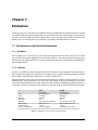
7 Evaluation
7.1 Environment and Overall Architecture . . . . . . . .
7.1.1 Hardware . . . . . . . . . . . . . . . . . . . .
7.1.2 Software . . . . . . . . . . . . . . . . . . . .
7.1.3 Conditions . . . . . . . . . . . . . . . . . . .
7.1.4 Application Architecture . . . . . . . . . . .
7.2 Correctness Verification . . . . . . . . . . . . . . . .
7.2.1 Scope . . . . . . . . . . . . . . . . . . . . . .
7.2.2 Description of the Test Method . . . . . . . .
7.2.3 Configurations . . . . . . . . . . . . . . . . .
7.3 Interrupt Latency . . . . . . . . . . . . . . . . . . . .
7.3.1 Scope . . . . . . . . . . . . . . . . . . . . . .
7.3.2 Method . . . . . . . . . . . . . . . . . . . . .
7.3.2.1 Modification in the Kernel Module
7.3.2.2 Setup . . . . . . . . . . . . . . . .
7.3.2.3 Automating and Data Analysis . . .
7.3.3 Results . . . . . . . . . . . . . . . . . . . . .
7.3.3.1 Data . . . . . . . . . . . . . . . . .
7.3.3.2 Summary . . . . . . . . . . . . . .
7.4 Scheduling Latency . . . . . . . . . . . . . . . . . . .
7.4.1 Scope . . . . . . . . . . . . . . . . . . . . . .
7.4.2 Method . . . . . . . . . . . . . . . . . . . . .
7.4.2.1 Exact Timing Measurements . . . .
7.4.2.2 Program Modifications . . . . . . .
7.4.2.3 Setup . . . . . . . . . . . . . . . .
7.4.3 Results . . . . . . . . . . . . . . . . . . . . .
7.4.3.1 Data . . . . . . . . . . . . . . . . .
7.4.3.2 Summary . . . . . . . . . . . . . .
.
.
.
.
.
.
.
.
.
.
.
.
.
.
.
.
.
.
.
.
.
.
.
.
.
.
.
.
.
.
.
.
.
.
.
.
.
.
.
.
.
.
.
.
.
.
.
.
.
.
.
.
.
.
.
.
.
.
.
.
.
.
.
.
.
.
.
.
.
.
.
.
.
.
.
.
.
.
.
.
.
.
.
.
.
.
.
.
.
.
.
.
.
.
.
.
.
.
.
.
.
.
.
.
.
.
.
.
.
.
.
.
.
.
.
.
.
.
.
.
.
.
.
.
.
.
.
.
.
.
.
.
.
.
.
.
.
.
.
.
.
.
.
.
.
.
.
.
.
.
.
.
.
.
.
.
.
.
.
.
.
.
.
.
.
.
.
.
.
.
.
.
.
.
.
.
.
.
.
.
.
.
.
.
.
.
.
.
.
.
.
.
.
.
.
.
.
.
.
.
.
.
.
.
.
.
.
.
.
.
.
.
.
.
.
.
.
.
.
.
.
.
.
.
.
.
.
.
.
.
.
.
.
.
.
.
.
.
.
.
.
.
.
.
.
.
.
.
.
.
.
.
.
.
.
.
.
.
.
.
.
.
.
.
.
.
.
.
.
.
.
.
.
.
.
129
129
130
130
.
.
.
.
.
.
.
.
.
.
.
.
.
.
.
.
.
.
.
.
.
.
.
.
.
.
.
.
.
.
.
.
.
.
.
.
.
.
.
.
.
.
.
.
.
.
.
.
.
.
.
.
.
.
.
.
.
.
.
.
.
.
.
.
.
.
.
.
.
.
.
.
.
.
.
.
.
.
.
.
.
.
.
.
.
.
.
.
.
.
.
.
.
.
.
.
.
.
.
.
.
.
.
.
.
.
.
.
.
.
.
.
.
.
.
.
.
.
.
.
.
.
.
.
.
.
.
.
.
.
.
.
.
.
.
.
.
.
.
.
.
.
.
.
.
.
.
.
.
.
.
.
.
.
.
.
.
.
.
.
.
.
.
.
.
.
.
.
.
.
.
.
.
.
.
.
.
.
.
.
.
.
.
.
.
.
.
.
.
.
.
.
.
.
.
.
.
.
.
.
.
.
.
.
.
.
.
.
.
.
.
.
.
.
.
.
131
131
131
131
132
132
132
132
133
133
134
134
134
135
136
136
137
137
137
138
138
140
140
141
141
142
142
142
8 Summary and Outlook
145
8.1 Summary . . . . . . . . . . . . . . . . . . . . . . . . . . . . . . . . . . . . . . . . . 145
8.2 Outlook . . . . . . . . . . . . . . . . . . . . . . . . . . . . . . . . . . . . . . . . . . 146
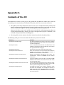
A Contents of the CD
147
References
149
Glossary
155
Table of Abbreviations
159
Index
163
Contents
9
10
Contents
List of Tables
1.1
Quantities of byte . . . . . . . . . . . . . . . . . . . . . . . . . . . . . . . . . . . .
21
2.1
RTAI kernel modules . . . . . . . . . . . . . . . . . . . . . . . . . . . . . . . . . . .
40
4.1
4.2
4.3
4.4
Symbols that are exported by the MOST base driver . . .
Methods that a MOST device structure provides . . . . .
Valid ioctl request codes for NetService device files . .
Events to trace the synchronous transfer over the PCI bus
62
66
69
82
5.1
5.2
POSIX system calls and their RTDM counterparts . . . . . . . . . . . . . . . . . . . 88
Predefined memory copy operations of the RTNRT framework . . . . . . . . . . . . 107
7.1
7.2
7.3
7.4
7.5
Computers used for the measurements . .
Measuring environments used in the tests
Events to measure the interrupt latency . .
Measured interrupt latencies . . . . . . .
Measured scheduling latencies . . . . . .
.
.
.
.
.
.
.
.
.
.
.
.
.
.
.
.
.
.
.
.
.
.
.
.
.
.
.
.
.
.
.
.
.
.
.
.
.
.
.
.
.
.
.
.
.
.
.
.
.
.
.
.
.
.
.
.
.
.
.
.
.
.
.
.
.
.
.
.
.
.
.
.
.
.
.
.
.
.
.
.
.
.
.
.
.
.
.
.
.
.
.
.
.
.
.
.
.
.
.
.
.
.
.
.
.
.
.
.
.
.
.
.
.
.
.
.
.
.
.
.
.
.
.
.
.
.
.
.
.
.
.
.
.
.
.
.
.
.
.
.
.
.
.
.
.
.
.
.
.
.
.
.
.
.
.
.
.
.
.
.
.
.
.
.
.
.
.
.
.
.
.
.
.
.
.
131
132
136
137
142
A.1 CD contents . . . . . . . . . . . . . . . . . . . . . . . . . . . . . . . . . . . . . . . . 148
11
12
List of Tables
List of Figures
2.1
2.2
2.3
2.4
2.5
2.6
2.7
2.8
2.9
2.10
2.11
2.12
2.13
2.14
Standardised PCI configuration registers . . . . . . . . . . . . . . . . . . . .
Running RTAI tasks and Linux tasks simultaneously . . . . . . . . . . . . .
Interrupt pipeline of ADEOS . . . . . . . . . . . . . . . . . . . . . . . . . .
Stodolsky Interrupt protection scheme . . . . . . . . . . . . . . . . . . . . .
Typical architecture for a RTAI real-time application . . . . . . . . . . . . .
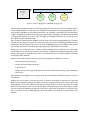
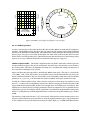
Typical MOST network with ring topology . . . . . . . . . . . . . . . . . . .
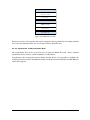
Structure of a MOST frame . . . . . . . . . . . . . . . . . . . . . . . . . . .
Structure of a control message . . . . . . . . . . . . . . . . . . . . . . . . . .
Typical MOST hardware configuration . . . . . . . . . . . . . . . . . . . . .
MOST network stack . . . . . . . . . . . . . . . . . . . . . . . . . . . . . . .
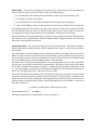
Schematic view of the MOST PCI Board . . . . . . . . . . . . . . . . . . . .
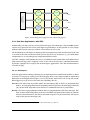
Data flow between the PCI bus and the MOST network for synchronous data
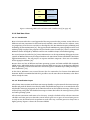
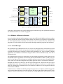
OptoLyzer PC Interface Box . . . . . . . . . . . . . . . . . . . . . . . . . . .
MOST Access DLL . . . . . . . . . . . . . . . . . . . . . . . . . . . . . . . .
.
.
.
.
.
.
.
.
.
.
.
.
.
.
.
.
.
.
.
.
.
.
.
.
.
.
.
.
.
.
.
.
.
.
.
.
.
.
.
.
.
.
.
.
.
.
.
.
.
.
.
.
.
.
.
.
28
36
37
38
42
45
46
47
48
49
50
52
53
54
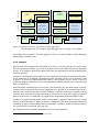
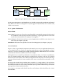
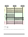
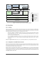
Structure of the Linux driver modules . . . . . . . . . . . . . . . . . . . . . . . . .
Data structures used to handle low and high drivers in the base module . . . . . . .
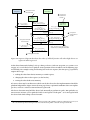
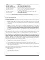
Sequence diagram that shows the order of callback function calls when high drivers
are registered and deregistered . . . . . . . . . . . . . . . . . . . . . . . . . . . . .
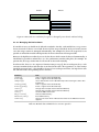
4.4 Potential race condition if a register is changed by two threads without locking . . .
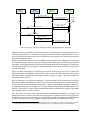
4.5 Sequence diagram showing the interrupt propagation to userspace . . . . . . . . .
4.6 Relationship between the different parts of the NetServices library . . . . . . . . . .
4.7 Basic structure of the service thread . . . . . . . . . . . . . . . . . . . . . . . . . .
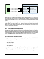
4.8 Routing MOST data and accessing the routed parts by two different applications in
the system . . . . . . . . . . . . . . . . . . . . . . . . . . . . . . . . . . . . . . . .
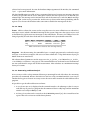
4.9 DMA receive buffer and software receive buffer . . . . . . . . . . . . . . . . . . . .
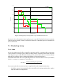
4.10 Synchronous data on the PCI bus . . . . . . . . . . . . . . . . . . . . . . . . . . . .
62
63
4.1
4.2
4.3
65
66
70
71
73
77
78
84
5.1
5.2
5.3
5.4
5.5
5.6
5.7
Schematic view about the position of the RTDM in a RTAI system . . . . . . . . . .
Which functions should be implemented as RTDM driver and which as Linux driver?
Simple character device driver using the PCI framework of Linux . . . . . . . . . .
Interrupt processing when using RT and non RT interrupt handlers for the same IRQ
Expansion of the macros that are provided by rt-nrt.h . . . . . . . . . . . . . . . . .
Spinlocks implementation on Linux and RTAI on uni-processor systems . . . . . . .
Race condition with RTDM Events when multiple readers wait . . . . . . . . . . . .
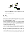
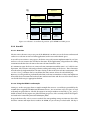
6.1
Structure of the real-time modules for MOST . . . . . . . . . . . . . . . . . . . . . 126
7.1
7.2
7.3
7.4
Data flow in the measurements . . . . . . . . . . . . . . . . . . .
Data flow when using two MOST interface cards in one computer
Data flow in the measurements . . . . . . . . . . . . . . . . . . .
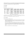
Histogram of interrupt latencies of a standard Linux kernel . . . .
.
.
.
.
.
.
.
.
.
.
.
.
.
.
.
.
.
.
.
.
.
.
.
.
.
.
.
.
.
.
.
.
.
.
.
.
.
.
.
.
87
91
91
96
99
101
104
133
134
135
138
13
7.5
7.6
7.7
7.8
7.9
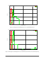
Histogram of interrupt latencies under RTAI . . . . . . . . . . . . . . . . . . . . . .
Histogram of interrupt latencies under Xenomai . . . . . . . . . . . . . . . . . . . .
Data layout of the time stamp inserted in the MOST data . . . . . . . . . . . . . . .
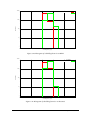
Histogram of scheduling latencies on a standard Linux kernel . . . . . . . . . . . .
Histogram of scheduling latencies of a standard Linux kernel where the task has RT
priority . . . . . . . . . . . . . . . . . . . . . . . . . . . . . . . . . . . . . . . . . .
7.10 Histogram of scheduling latencies on RTAI . . . . . . . . . . . . . . . . . . . . . . .
7.11 Histogram of scheduling latencies on Xenomai . . . . . . . . . . . . . . . . . . . .
14
139
139
141
143
143
144
144
List of Figures
Listings
2.1
2.2
2.3
2.4
2.5
2.6
4.1
4.2
4.3
4.4
4.5
5.1
5.2
5.3
5.4
5.5
5.6
5.7
5.8
5.9
5.10
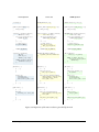
Minimal kernel module which prints “Hello world” . . . . . . . . . . . . .
Registration of a PCI device driver in Linux . . . . . . . . . . . . . . . . .
Using sequence locks . . . . . . . . . . . . . . . . . . . . . . . . . . . . . .
Definition of struct timespec and struct timeval . . . . . . . . . . . .
Real-time task that runs in kernel space and prints a message periodically .
Real-time in userspace using LXRT . . . . . . . . . . . . . . . . . . . . . .
Low and High driver structure . . . . . . . . . . . . . . . . . . . . . . . .
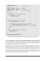
Sending a control packet using MOST NetServices . . . . . . . . . . . . . .
Routing MOST channels to receive them over the PCI interface . . . . . . .
Data stored per synchronous device . . . . . . . . . . . . . . . . . . . . .
Data stored per synchronous file . . . . . . . . . . . . . . . . . . . . . . .
Simple example that shows how to use the RTDM in an application . . . .
An example for a struct rtdm_device definition . . . . . . . . . . . . . .
Using the device context in the RTDM . . . . . . . . . . . . . . . . . . . .
Showing a kernel thread in use . . . . . . . . . . . . . . . . . . . . . . . .
Port of listing 5.4 on page 109 to RTDM . . . . . . . . . . . . . . . . . . . .
Using a timeout sequence . . . . . . . . . . . . . . . . . . . . . . . . . . .
Example using timer and tasklets in Linux . . . . . . . . . . . . . . . . . .
Porting timers and tasklets using RTDM tasks . . . . . . . . . . . . . . . .
Simple timer tasklet in RTAI . . . . . . . . . . . . . . . . . . . . . . . . . .
Simple alarm in Xenomai . . . . . . . . . . . . . . . . . . . . . . . . . . .
.
.
.
.
.
.
.
.
.
.
.
.
.
.
.
.
.
.
.
.
.
.
.
.
.
.
.
.
.
.
.
.
.
.
.
.
.
.
.
.
.
.
.
.
.
.
.
.
.
.
.
.
.
.
.
.
.
.
.
.
.
.
.
.
.
.
.
.
.
.
.
.
.
.
.
.
.
.
.
.
.
.
.
.
.
.
.
.
.
.
.
.
.
.
.
.
.
.
.
.
.
.
.
.
.
24
29
32
33
39
41
64
74
76
80
80
88
92
93
109
110
116
118
119
121
122
15
16
Listings
Abstract
This thesis shows the porting process for drivers from Linux to real-time Linux extensions. The main focus is on RTAI, but Xenomai is also viewed.
After giving an overview about the basics which includes Linux drivers, real-time extensions for Linux, real-time drivers and the MOST bus, the design of the Linux driver
for MOST is described. This driver was developed in this work. The resulting MOST
driver supports MOST NetServices and access to synchronous data for both Linux and
real-time Linux.
An overview about the driver model of RTAI and Xenomai called RTDM is given which
includes access to the devices from the application side. In the main part, the porting
process is described. Well-known idioms that are used in Linux device drivers like resource management, interrupt handling, synchronisation, memory allocation, memory
copying, timers and tasklets are presented how to port them easily to the real-time
world.
The end-design of the real-time driver for MOST is shown which also states the partitioning of functionality between Linux and real-time Linux on a concrete example.
Finally, sample applications in userspace are described which test the functionality of
the driver. They are also used for timing measurements that show the interrupt and the
scheduling latency of the operating system on the example of the MOST driver. A short
assessment about the results of the measurements is given afterwards.
17
18
Listings
Chapter 1
Introduction
1.1 About the Topic of this Thesis
Today, Linux is not only used as desktop and server operating system but also in embedded devices.
It’s often necessary to meet real-time constraints in this sector, but it is still desirable to have Linux
for non real-time tasks like the user interface. One advantage is the availability of good Open Source
components to build this applications rapidly.
Because the Linux kernel cannot meet hard real-time conditions, there are various real-time kernels
that run together with the Linux kernel so that the system designer has both a real-time and a
general-purpose operating system running on the same hardware.
Real-time applications often access special hardware devices like analogue-to-digital converters. If
the hardware is complex and used by more than one application, it makes sense not to address the
device in the application directly but to build a device driver as known in common operating systems
like Linux or Windows.
For Linux, there exist lots of Open Source device drivers. Some of the devices are also useful for
real-time applications. To use the device in such an application, it is not possible to simply open the
Linux device file or socket and operate on the device as done in a normal Linux application. That’s
because the timing constraints of the application could not be guaranteed any more. Instead, the
driver must be ported to use the capabilities and interrupt handling mechanism of the real-time
kernel.
Although there already exists some real-time device drivers for RTAI—the real-time Linux flavour
we’ll focus on in this thesis—, there is no documentation available that describes how to port a Linux
driver to real-time Linux. In addition, most RTAI drivers are written from scratch so it’s not possible
to compare their Linux implementation with the RTAI implementation.
The best way to show the porting procedure was to actually port a Linux driver to RTAI because
then the concepts showed in theory can be proofed in practise. It is also easier to understand if a
concrete example is provided. The reason why no already existing driver was taken is that there was
no hardware available that has a Linux driver and that is
• interesting for real-time applications (for example, a “real-time webcam” with a non real-time
USB interface doesn’t make much sense),
• not too easy (like a parallel port) because the major concepts used in device drivers should be
shown and
• not too difficult (like a complete network stack) because the focus of this work should be on
the porting process, not on the example.
19
MOST was used because it’s widely used in the automotive industry, so it makes sense to have a Linux
driver available for MOST hardware. The synchronous data transfer with MOST is real-time capable,
the documentation was available for free and there was a affordable PCI hardware obtainable.
1.2 Overview
The following section should give a quick overview about the contents of each chapter:
Chapter 2 introduces the basic concepts and terms used in this thesis. This is about real-time
operating systems and real-time Linux extensions in general, RTAI as the example used in this
paper, Linux and RTAI device drivers and the MOST network.
Chapter 3 analyses the requirements. It sums up the properties that the resulting drivers must have
and analyses also the timing constraints of the system.
Chapter 4 describes the structure and implementation of the Linux kernel modules and the applications and libraries in userspace.
Chapter 5 is the most important chapter from the view of the initial goal because it describes the
porting process of a Linux driver to RTAI with all it’s problems and pitfalls. The description
is independent of the MOST driver and can be considered as “cookbook” is another driver
should be ported.
Chapter 6 summarises the structure of the end product: the RTAI driver. It is based on chapter 4 but
can be read independent of chapter 5.
Chapter 7 presents a comparison of the timing critical part of the two drivers. This is to show that
the real-time demands are met in the RTAI driver and to compare this with the (non real-time
capable) Linux driver.
Chapter 8 summarises the cognition of this paper and mentions issues that have not been covered
in this thesis but which are also worth to take a look at it.
1.3 Conventions
1.3.1 Terms
The thesis frequently uses the terms “Linux” and “Windows” for the referred operating systems.
Following definitions should precise their usage:
Linux The term “Linux” has two meanings which can be distinguished from the context. The original
meaning is the Linux kernel, i. e. that software you can download from ftp://ftp.kernel.org, the
core of the operating system.
Because people started to build whole operating systems based on the Linux kernel, i. e. they
combined it with the already-existing GNU software which includes a C library, a shell, a
compiler and various utility programs, in most common speech this whole collection is called
Linux operating system.
People who want to emphasise that the largest part of a “Linux operating system” is from the
Free Software Foundation (FSF), call it also GNU/Linux.
20
Chapter 1 Introduction
Windows The term “Windows” refers to the current NT-based versions of Microsoft Windows, i. e. at
the time this thesis was written Microsoft Windows NT4, Microsoft Windows 2000 and Microsoft
Windows XP.
This does not mean that some statements are not also true for other versions of Microsoft
Windows like Windows 95/98/ME or even Windows CE. If a statement is only valid for a special
version, this is mentioned in the text additionally.
1.3.2 Units
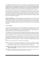
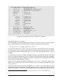
According to IEC 60027-2 [1] [2], storage capacities are referred with following terms:
Name
kilobyte
megabyte
gigabyte
Symbol
kB
MB
GB
Quantity
103
106
109
Name
kibibyte
mebibyte
gibibyte
Symbol
KiB
MiB
GiB
Quantity
210
220
230
Table 1.1: Quantities of bytes [2]
1.3.3 Typographical Conventions
• Terms explained in the glossary are prefixed with an arrow symbol (û).
• Cross references are symbolised with a hand symbol (+).
• Bold is used to mark important terms and headers.
• Italics is used for new words and highlighting of text in general.
• Typewriter is used for source code, variable names and shell commands.
• Function names are printed in typewriter followed by a pair of brackets () while system calls
have no brackets.
• Serif font is used for hardware registers, file names and internet resources.
1.4 Source Code
1.4.1 Listings
The listings in this thesis should show how to implement some features. Most listings are not
compilable because of missing include statements or other details that are not important to show the
idea. However, the CD which is attached to this thesis contains the fully compilable source code in
the directory /development/thesis-examples/ including a Makefile where appropriate. This is only
valid for listings that contain programs, not for simple declarations or function prototypes.
See also Appendix A on page 147.
1.4 Source Code
21
1.4.2 Original Software Code
While there exists rich documentation for the Linux kernel, there’s not so much documentation
for RTAI and Xenomai. In both cases looking at the source code can be useful or necessary. The
following web-pages provide a cross-linked source code browser that makes it easy to browse the
code:
• Linux: http://www.rts.uni-hannover.de/linux/lxr/source
• Xenomai: http://www.rts.uni-hannover.de/xenomai/lxr/source
• RTAI: http://www.rts.uni-hannover.de/rtai/lxr/source
The software used to generate these browsers is available at http://lxr.linux.no where also an outdated
Linux repository is provided.
The compressed sources are also available on the CD in the directory /software/tarballs/.
1.4.3 MOST Driver and Utilities
It is planned to put all software that was developed for this thesis under an Open Source license and
make it available to the public. However, at the time the thesis was finished, the official permission
was still outstanding—mainly because it was still in the holiday period. So it was too late to include
the software on the public CD that is attached to this thesis.
The Open Source project will be launched in on http://most4linux.sourceforge.net and this is also
the place where the source code can be found as soon as it’s released to the public.
22
Chapter 1 Introduction
Chapter 2
Basics
2.1 Linux Device drivers
The following section should give the reader a short overview about device drivers in the Linux
operating system. Device drivers are covered in [3] and [4]. It’s also worth reading [5] and [6] which
gives a general overview about the design and implementation of the Linux kernel. In the following
section it is assumed that the reader is familiar with generic concepts of operating systems and Linux.
A good book that covers that topic is [7].
2.1.1 Kernel Modules
Linux is a monolithic operating system. This means that the kernel completely runs in supervisor
mode of the processor with all parts in the same address space. In other words: Each part of the
kernel can access each other part, can call all functions and see all its memory. They communicate
with function calls and shared memory just as the parts of a user process do.
However, one major task of the kernel is to manage devices. Because each user has different devices
and supporting all possible devices with one kernel would be a huge waste of memory, it would be
necessary to compile a kernel for each system separately.
To be able to provide one kernel for all systems of a specific category (like uni-processor IA-32-based
systems) and for several other reasons listed in [8, section 2.3], so-called kernel modules can be
dynamically loaded at run-time. Kernel modules are simple object files (.o), linked together with
some information to a kernel object file (.ko)1 . Just as other kernel code, kernel modules have to be
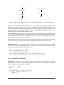
programmed in the C programming language2 .
Kernel modules can add arbitrary code to the kernel, not only device drivers but also network
protocols or file systems [8, section 2.4]. Most parts of the kernel can be compiled in or configured as
module. This can be chosen with a configuration tool before compiling the kernel. In pre-compiled
kernel images as shipped with Linux distributions, most parts are compiled as a module.
If the user requests to load the module with the insmod or modprobe command (or another system
event such as plugging in a hardware device), the kernel allocates memory for the module, copies the
module in that memory, resolves all symbols and executes the start routine.
1
2
[9] contains more information how the build process works and especially how a .o file is linked to a .ko file.
There are patches available that enable Linux to support C++ in the kernel. One patch is http://netlab.ru.is/exception/
LinuxCXX.shtml.
23
1
2
#include <linux/init.h>
#include <linux/module.h>
3
4
5
6
7
static int __init hello_init(void) {
printk(KERN_ALERT "Hello World\n");
return 0;
}
8
9
10
11
static void __exit hello_exit(void) {
printk(KERN_ALERT "Goodbye, world\n");
}
12
13
14
15
16
MODULE_LICENSE("GPL");
/* required */
_
MODULE AUTHOR("Some unknown entity"); /* optional */
module_init(hello_init);
module_exit(hello_exit);
Listing 2.1: Minimal kernel module which prints “Hello world”
As a difference to other kernel code, a loadable module only has access to symbols exported with
EXPORT_SYMBOL() or EXPORT_SYMBOL_GPL() macros3 . Symbols can be global variables and functions. Each module can export additional symbols; other modules loaded at a later time have access
to these new symbols.
Kernel modules usually provide two functions:
• An initialisation function is called if the module is loaded. It usually scans for hardware,
registers functions that are called later and allocates memory. Such functions can be callback
functions at different subsystems like the PCI subsystem or interrupt handlers.
This function is required to load the kernel module.
• A clean up function usually reverts all the steps done in the initialisation function in reverse
order. It is possible for a module to provide only the initialisation function; this means that it
is impossible to unload the module
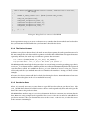
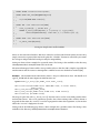
As an example, a minimal “Hello World” module is shown in listing 2.1. The printk() function
outputs the message in the kernel ring buffer. This buffer can be displayed with the dmesg command
and is normally also redirected to a log file, usually /var/log/syslog or /var/log/messages.
The reason why the license of the module must be specified in the module source code is that only
modules with a GPL-compatible license such as ûGPL itself or the ûBSD license are supported by
the kernel developers. If a proprietary module is loaded, a so-called “tainted” flag is set. If this flag is
set, bug reports are ignored in the kernel mailing list because the source code of the module isn’t
available and that module could cause the problem and makes debugging much more complicated.
Most kernel developers think that proprietary kernel modules are even illegal because linking ûGPL
code with non-GPL code is not allowed in general [10] [11].
3
In addition there are the macros EXPORT_SYMBOL_GPL() and EXPORT_SYMBOL_GPL_FUTURE(). The first one states that
symbols exported by this macro only can seen by modules which specify the GPL as its license. The second exports the
symbol to all modules but marks the symbol to be changed to GPL-only in future. The file Documentation/featureremoval-schedule.txt in the kernel source code contains the date of the switch.
24
Chapter 2 Basics
2.1.2 Device Files and System Calls
In Linux and other Unix-like operating systems it’s common that device driver and userspace
communicate by using device files. Often this is hidden by an API provided by a shared library, but
that doesn’t change the driver’s point of view.
For an application, a device file can be treated just as any ordinary file. In particular, the following
system calls can be applied (among others):
• open to open the (device) file and get a handle to it, the file descriptor;
• close to close it and release resources;
• write to write data from the device (may block if the write buffer is full);
• read to read data (may block if the read buffer is empty);
• ioctl to control the behaviour of the device4 ;
• select or poll to wait for events on file descriptors or to check if a read or write operation
would block.
There are three categories of devices: Block devices, character devices and network devices. Both
block devices and character devices use device files, only network devices use the well-known sockets
as communication interface. The difference between block devices (mostly hard disks) and character
devices (all sort of devices, from a serial line to a USB webcam) is that block devices have operations
to access blocks of bytes while character devices can only read and write streams of data. In this
thesis, we’ll focus on character devices.
Device files can be created with the user command mknod. Each device file has a major device
number and a minor device number associated with it. The idea was originally that the major number
identifies the driver and the minor number identifies the device as there can be more instances of the
same device types (for example two SCSI hard disks). But it’s also possible to share a major device
number between more drivers as major device numbers are tight. For modules that are in the official
kernel source tree, the file Documentation/devices.txt contains the number mapping. For custom
device drivers, there’s a “local/experimental” range.
As devices are dynamic nowadays, there are mechanisms to create device files dynamically [12].
But that’s beyond the scope of this thesis. In embedded systems, the hardware is mostly known in
advance so static device files are still a sensible option even for “exotic” hardware.
2.1.3 Linux Driver API
The special thing about the driver API in Linux is that it doesn’t exist a “real” driver API. Of course,
there are exported API functions to perform specific tasks like registering an interrupt handler. But
the function is the same if some internal function in Linux registers an interrupt handler or if a
device driver does it. So there’s no abstraction layer between the kernel and device drivers.
Because in the ideal world, all drivers are ûOpen Source and are integrated in the kernel source tree,
this is no problem. If some function changes in the Linux API, all drivers are changed by the person
4
This system call only is useful on device files, not on ordinary files. It was introduced to control serial terminals (like
the baud rate) but it is used for various configuration calls that are not covered by other system calls. For normal files,
the fcntl call is common: It is used for example to lock files so that no other process can modify the file while one
process is accessing it.
2.1 Linux Device drivers
25
that changes the API function. Modules maintained externally often use conditional compilation to
work on different kernel versions.
[13] and [11] discusses the advantages of the Linux approach where no stable driver API exists.
2.1.4 The Proc FS and Other Virtual File Systems
In Linux, status information stored in kernel data structures is provided in the proc file system, usually
mounted to /proc. Examples for status information are the uptime of the system (/proc/uptime) or
process information (/proc/PID/). In fact, process information was the first application for this file
system and gave it its name.
Device drivers can add their own information to the proc file system just as other kernel code. If the
user accesses a proc file for reading, a function in the driver gets called and has the chance to output
the information it wants.
It should be mentioned that Linux has also other Virtual File Systems (VFS):
• sysfs (/sys) which provides device information in a fixed scheme [14] [15]. It is mainly used
by daemons which operate in userspace and support the kernel for example by creating the
correct device files as mentioned before;
• debugfs [16] used for debug information;
• usbfs [17, chapter 2] to write userspace drivers for USB and
• relayfs [18] for high-speed data relay.
In the MOST driver only the proc FS is used. The other VFS are not used beside of the automatic
usage of sysfs by the PCI subsystem.
2.1.5 Hardware Communication
Communicating with hardware in a device driver means
• accessing I/O ports;
• accessing I/O memory regions and
• responding to interrupts.
2.1.5.1 I/O Ports and I/O Memory
Hardware registers can be mapped in memory which makes it possible to address a hardware register
by dereferencing a pointer. Such memory is called I/O memory. Especially from the ISA bus on
the PC architecture, the concept of I/O ports is known: a separate address space for devices. The
programmer uses the inb and outb instructions to access the I/O space.
So the main difference between I/O memory and I/O ports is that to access I/O memory, the same
machine instructions can be used as to access RAM and special instructions are needed to access I/O
ports.
26
Chapter 2 Basics
As it’s important that only one device driver uses a certain resource, the Linux kernel has functions
that can allocate or release regions of I/O ports and I/O memory. After allocating an I/O region, the
I/O ports can be accessed in the driver. It is possible to use the inb and outb instructions in inline
assembly, but this is not recommended. It’s better to use the inb() and outb() (and also their word
and long word counterparts) macros because this makes the driver portable to other architectures
which don’t have special I/O port instructions, and use an external bridge for this task instead.
To access I/O memory, it must be made accessible by the driver first by calling the ioremap() function.
The kernel makes sure that the memory is accessible from the kernel virtual address space which
is not identical to physical address space. Special macros like ioread32() from <asm/io.h> are
provided to access the I/O memory after mapping. Dereferencing the pointer returned by ioremap()
doesn’t work on all platforms. It’s important to notice that these macros always return little-endian
values even if the system is big-endian.
Caching and reordering Linux automatically sets the required attribute “non-cachable” so that no
caching is performed. To prevent instruction reordering at compiler level, the barrier() operation
must be added in code places where reordering must be prevented. However, the hardware may
still reorder the instructions. To prevent this, rmb() (read memory barrier), wmb() (write memory
barrier) or mb() (combination of the two) must be added. See also [4, page 237 f.] for a more detailed
description.
2.1.5.2 Interrupts
Using interrupts in Linux device drivers is quite straightforward: at initialisation time, a normal
C function is registered by calling request_irq() with the IRQ number and a function pointer as
parameter. The low-level handling is done by the kernel (implemented in assembly language). If the
requested interrupt occurred, the function gets executed [4, page 268].
Linux supports interrupt sharing with the SH_IRQ flag when requesting the interrupt. If this flag is
set, the interrupt service routine must find out first if the interrupt was generated by the device for
which it is responsible. PCI drivers must support interrupt sharing according to the PCI specification.
Because long interrupt service routines influence the interrupt latency, Linux (as every modern
operating system) discriminates between primary and secondary interrupt handling—in Linux
terminology also called top halves and bottom halves. The “top half ” is the interrupt service routine
itself. It should be as short as possible, i. e. only time-critical activities should be processed in the
ISR.
There are three major mechanisms for secondary interrupt handling:
Tasklets are short pieces of code that can be registered to run at any time, especially in an interrupt
service routine. They get executed by the kernel at some later time (the precise time is simply
not specified) in interrupt context. See also softirqs in section 2.1.9 on page 34.
Workqueues invoke a workqueue function at some future time in the context of a special worker
context. The major difference compared with tasklets is that it runs in process context (+
section 2.1.7 on page 30).
Kernel threads are tasks running only in kernel mode. They also can be used for secondary interrupt
handling. An elaborately description can be found in [3, section 6.4]
2.1 Linux Device drivers
27
0x0
0x00
0x1 0x2
Vendor
ID
0x3
Device
ID
0x4
0x5
0x6
Command
Reg.
0x7
Status
Reg.
0x8
0x9
Rev.
ID
0xA 0xB
Class
Code
0x10
Base Address 0
Base Address 1
Base Address 2
0x20
Base Address 4
Base Address 5
CardBus
CIS pointer
0x30
Expansion ROM
Base Address
Reserved
0xC
0xD 0xE
0xF
Cache Lat. Head.
Line Timer Type BIST
Base Address 3
Subsystem Subsystem
Vendor ID Device ID
IRQ IRQ
Line Pin
Min. Max.
Gnt. Lat.
required
optional
Figure 2.1: The standardised PCI configuration registers
2.1.6 PCI
2.1.6.1 PCI Configuration
PCI is not only relevant for hardware manufacturers but also for system programmers. As PCI is
designed for “plug & play”, all resources a device needs are configured dynamically. The configuration
is usually done by the firmware before the Linux kernel is loaded. Each PCI device has a so-called
configuration address space . This is a special address space of 256 bytes which is geographically
addressable. Each slot for a card has the slot number as part of the address [19, section 11.2]. The
first 64 bytes of configuration space are standardised.
These bytes are shown in figure 2.1. The address is shown by the hexadecimal numbers on the left
and on the top. The Vendor ID and Device ID are used to identify a PCI card. The IRQ Line contains
the interrupt number. The Base Address Registers are explained below. A description of all other
registers can be found in [20, chapter 19].
Of course, Linux gives access to the bytes in configuration address space with a set of functions equal
on all supported platforms, for example the pci_bus_read_config_byte() function to read or the
pci_bus_write_config_byte() function to write a byte in the configuration address space.
As stated above, communication with a hardware device is done with I/O memory, I/O ports and an
interrupt handler. A PCI card may provide up to six base addresses, in figure 2.1 marked as Base
Address 0 to Base Address 5. These are also known as Base Address Registers (BAR). Each register
contains a base address. The least significant bit discriminates between I/O memory and I/O port5 .
The actual addresses of all registers on a device can now be calculated by adding the register offset to
one of the values in a Base Address Register. It’s listed in the hardware documentation which BAR is
responsible for a given region. Many devices use only one BAR, for example the MOST interface card
covered in this thesis.
2.1.6.2 The PCI Subsystem in Linux
In a Linux system, the driver corresponding to a device can be loaded automatically. The driver must
contain the vendor, device, subsystem vendor and subsystem device ID for which it is responsible6 .
5
6
[20, page 381 ff.] explains how to calculate the length of an I/O or memory region.
It is also possible that a device belongs to a device class. This is common for devices from different vendors that all have
the same programming model like USB 2.0 EHCI host controllers.
28
Chapter 2 Basics
1
#include <linux/pci.h>
2
3
4
5
6
7
8
9
10
11
12
13
static const struct pci_device_id test_pci_ids[] = {
{ PCI_DEVICE(VENDOR_ID_TEST, DEVICE_ID_TEST) },
{ 0 }
};
static int test_probe(struct pci_dev *dev, const struct pci_device_id *id) {
pr_info("Device discovered\n");
return 0;
}
static void test_remove(struct pci_dev *dev) {
pr_info("Device removed\n");
}
14
15
16
17
18
19
20
21
22
23
24
25
26
27
MODULE_DEVICE_TABLE(pci, test_pci_ids);
static struct pci_driver pci_driver = {
.name
= "pci_test",
_
.id table = test_pci_ids,
.probe
= test_probe,
.remove
= test_remove
};
int __init pci_test_init(void) {
return pci_register_driver(&pci_driver);
}
void __exit pci_test_exit(void) {
return pci_unregister_driver(&pci_driver);
}
28
29
30
module_init(pci_test_init);
module_exit(pci_test_exit);
Listing 2.2: Registration of a PCI device driver in Linux
The IDs are listed in a table in the driver source code. See listing 2.2 for an example.
In the Linux kernel, PCI is hot-pluggable. There is very few hardware which supports hot-plugging
of PCI devices, but in Linux all new drivers use this programming model. Each driver registers a
probe() and a remove() function at the PCI subsystem.
Normally, the hardware is not hot-plugging capable so the card is already plugged in if the driver
is loaded and it is still plugged in if the driver is unloaded. So in this case, the probe() function is
called when the driver is loaded and the remove() function is called when the driver is unloaded. If
the driver is installed permanently in the system, this is at system boot and shutdown.
Listing 2.2 shows how this works in source code. This programming style is ubiquitous in Linux: A
structure contains data elements and function pointers, this structure is registered somewhere and
the functions get called from the kernel internals.
2.1 Linux Device drivers
29
2.1.7 Managing Concurrency
Before Linux 2.0, managing concurrency was easy: The kernel was non-preemptable and non SMPcapable. So the only problem was that kernel code could be preempted by interrupt service routines.
This was easily solvable by disabling interrupts temporarily. Of course, semaphores were needed for
synchronisation between drivers and tasks.
However, times have changed dramatically. The kernel 2.6 which was used in this thesis, supports
both SMP and is also preemptable. Preemption was introduced without new synchronisation mechanisms at driver level; it uses the same mechanisms as for concurrency between more processors.
2.1.7.1 Contexts
It is important to discriminate between two contexts in which kernel code can run:
Task context Code runs in task context if the task currently running is doing a system call. This
means that the current pointer, which holds the task currently executing, is valid. Especially
the current thread of execution can sleep. Some operations require sleeping where it’s not
obvious instantly such as allocating a large amount of memory where swapping out some
pages may be required.
Also, kernel threads run in task context. A kernel thread is a special task that only runs in
kernel mode and that is usually created and killed by kernel code7 .
Interrupt context All code which is indirectly started by an interrupt is in interrupt context. This
means that the thread of execution cannot sleep, but non-blocking kernel functions can be
called such as waking up tasks. Not only interrupt service routines run in interrupt context
but also tasklets (+ 2.1.5.2 on page 27).
The kernel offers macros to test if a function is in interrupt or process context:
• in_irq() tests if the code is called from an interrupt service routine;
• in_softirq() tests if the code is called from a softirq handler [6, page 173] which includes
tasklets;
• in_interrupt() is true if in_irq() or in_softirq() is true;
• in_atomic() is true if code can sleep. This is done by evaluating the preemption counter.
All these macros are defined in <linux/hardirq.h>. The kernel also offers debugging facility which
checks if the code is allowed to sleep and prints an error message if not. To enable this, the DEBUG_
SPINLOCK_SLEEP option must be set when compiling the kernel.
7
Kernel threads can also be killed from userspace. They are shown as normal tasks with the ps command, marked with
square brackets ([]).
30
Chapter 2 Basics
2.1.7.2 Mechanisms
Linux offers the following synchronisation mechanisms:
Semaphores Semaphores are a well-known concept for managing critical sections as well as synchronisation (blocking a task and waking it up again). Linux has no different implementations of
binary semaphores and general semaphores. They’re all of the data type struct semaphore.
However, there are special reader/writer semaphores. They allow multiple readers accessing
the same data concurrently as long as no writer is in the critical section.
Mutexes Kernel 2.6.16 and newer versions provide a special mutex implementation that is faster
than using a semaphore for this task. [21] provides a description and some performance
comparisons.
Completions This is a special synchronisation mechanism where a thread initialises some activity
in another thread and then waits for that activity to complete. This could be modelled with a
semaphore as well, but not in an optimal way. See [4, page 114 f.] for details.
Spinlocks As semaphores can block, it’s not possible to use semaphores in interrupt context. Additionally, the overhead of putting a task in sleep state is too much if the critical sections
are only a few CPU cycles short. For this situation, spinlocks are used: The CPU does active
waiting (“spinning”) until the other process leaves the critical region. Spinlocks are of type
spinlock_t, and the most important operations are spin_lock() and spin_unlock().
If the data protected by spinlocks are also accessed in interrupt service routines, the interrupt
on the CPU holding the lock must be disabled. Without this, the interrupt service routine
could get active and tries to acquire the lock but it could never get it because the code that
could free the lock runs in task context. So this leads to a deadlock.
To prevent this this, the function spin_lock_irqsave() must be used, together with spin_
unlock_irqrestore(). Reader/writer spinlocks are also available.
Sequence locks So-called seqlocks are used if writing to a variable that must be protected against race
conditions must be fast and reading can be repeated. If the variable was written while another
thread reads it at the same time, the read is repeated. An example is shown in listing 2.3 on the
following page. However, only one thread can write at the same time so for write protection a
normal spinlock is used internally.
Sometimes, locking can be avoided by using the right algorithms. The kernel provides some help for
this [4, page 123 ff.]:
Circular buffers If there’s only one reader and one writer using a circular buffer, there’s no locking
needed. Linux has a common implementation for circular buffers in <linux/kfifo.h>.
Atomic variables If the shared resource is only an integer, the type atomic_t can be used. It holds an
integer value and provided some operations like atomic_sub_and_test() that are optimised
for the specific architecture and that require no additional locking.
2.1 Linux Device drivers
31
1
#include <linux/seqlock.h>
2
3
4
unsigned int
seqlock_t
seq;
the_lock;
5
6
7
8
9
do {
seq = read_seqbgegin(&the_lock);
/* some activity */
} while (read_seqretry(&the_lock, seq));
Listing 2.3: Using sequence locks
2.1.8 Timestamps
2.1.8.1 Hardware Timers
Often it’s desirable to know the current time for example for timing measurements or if a timestamp
should be added to a data packet. Each time information must based on hardware timing chips. On
the PC architecture, following hardware timers are available [6, page 228 ff.]:
• the Real Time Clock (RTC) which stores the time in days, month and hours etc. even if the
power is turned off;
• the Time Stamp Counter (TSC) register which is incremented each clock cycle (only Pentium
processors and above) and
• the Programmable Interval Timer (PIT) that can be used to trigger periodic timing interrupts.
Beside of these three basic timer there are also on new systems
• the CPU Local Timer (also called APIC timer) that is necessary on multi processor systems;
• the High Precision Event Timer (HPET) that should replace the PIT in the long run and
• the ACPI Power Management Timer that is necessary if the TSC is unusable because of CPU
frequency adjustments.
In the following description, only the “old” timers and uni-processor systems are considered. The
timers that Linux uses depends on the available hardware. On each boot, the available timers are
detected.8 Normally, the PIT is used to generate the timing interrupt and the TSC is used for a finer
granularity.
2.1.8.2 Linux Timekeeping Architecture
In Linux, the kernel time is represented by a global variable called jiffies_64 that is incremented
each timer interrupt. The frequency is configurable at compile-time9 . On PC systems, 250 Hz or
1000 Hz are typical. The global macro HZ offers the current frequency.
8
Which timer the currently available Linux system uses can be read in the boot messages. After the boot process, type
dmesg | grep "high-res time" to get out the timer.
9
The configuration options are CONFIG_HZ_100, CONFIG_HZ_250 and CONFIG_HZ_1000. The option is located in Processor
type and features → Timer frequency in the kernel configuration system.
32
Chapter 2 Basics
1
2
typedef long
typedef __kernel_suseconds_t
__kernel_suseconds_t;
suseconds_t;
3
4
5
6
7
struct timeval {
time_t
tv_sec;
suseconds_t tv_usec;
};
/* seconds since 1970-01-01 00:00 UTC */
/* microseconds */
struct timespec {
time_t
tv_sec;
long
tv_nsec;
};
/* seconds since 1970-01-01 00:00 UTC */
/* nanoseconds */
8
9
10
11
12
Listing 2.4: Definition of struct timespec and struct timeval
This global variable should only be accessed by get_jiffies_64() on 32-bit systems because a read
to a 64-bit variable is not atomic and may produce wrong results if the jiffies variable is updated.
However, since mostly a 32-bit timestamp is sufficient, the jiffies variable maps to the lower 32-bit
of the 64-bit timestamp. Because it can overflow, the following macros must be used to compare
jiffies-based timestamps [4, page 185]:
int
int
int
int
time_after(unsigned long a, unsigned long b);
time_before(unsigned long a, unsigned long b);
time_after_eq(unsigned long a, unsigned long b);
time_before_eq(unsigned long a, unsigned long b);
Also, there are conversion functions that are easier to use than fiddling with HZ. They are defined in
<linux/jiffies.h>:
unsigned
unsigned
unsigned
unsigned
int jiffies_to_msecs(const unsigned long
int jiffies_to_usecs(const unsigned long
long msecs_to_jiffies(const unsigned int
long usecs_to_jiffies(const unsigned int
j);
j);
m);
u);
When absolute time is required, this is represented with struct timeval (which is used for microsecond precision) or struct timespec (for nanosecond precision) on POSIX systems. Listing 2.4
shows their definition.
Linux stores the current time in this format in the global xtime variable. Direct use of this variable
is discouraged because it’s difficult to atomically access both of the field [4, page 189]. Instead, the
function
struct timespec current_kernel_time(void);
should be used. Both the xtime and the jiffies_64 variable are protected by a sequence lock
internally. The disadvantage of using xtime or current_kernel_time() is that the variable is only
updated every tick and so it’s inaccurate.
The time value in userspace applications is returned by the gettimeofday system call. In kernelspace,
do_gettimeofday() implements this system call. This function is also exported so it can directly
be used in kernel code. The advantage of this function is that it not only used xtime to retrieve the
2.1 Linux Device drivers
33
current system time but it also uses the TSC stamp to get the difference between the last timer tick
and the moment the function was called.
There’s also the getnstimeofday() function that fills a struct timespec which has nanosecond
precision instead of only milliseconds. The drawback is that so-called time interpolators [22] are
needed to get this high-precision time information. Currently, only ûIA-64 provides this10 . On
other architectures, the function is implemented by using do_gettimeofday() so it does not add
precision.
Monotonic time vs. wall-clock time The xtime variable, the do_gettimeofday() and the
getnstimeofday() function represent the wall-clock time which means that if the time of the
system clock is changed (by the user or by a ûdaemon), the value isn’t monotonically increasing any
more. The kernel provides also monotonic time sources but this isn’t covered here, see [6, chapter 6]
for this.
High Resolution Timers Since kernel 2.6.16, the high resolution timer framework [23] [24] has
been included. nanosleep, i-timers and POSIX timers are implemented on top of the hrtimers.
However, the hrtimers framework doesn’t provide a high-resolution timer source. Such one can be
found in the internet for example as part of the hrt-dyntick patch from Ingo Molnar and Thomas
Gleixner available at http://www.tglx.de/projects/hrtimers/. This patch also provides a tick-less
kernel [25].
An easy example program shows the difference: It only collects time stamps with the clock_gettime() function and the CLOCK_REALTIME parameter. The return value of the function is a timestamp
of type struct timespec. If the kernel was built without the patch, the lower three digits of the
nanoseconds part are always zero. If the patch was applied and the kernel was built with CONFIG_
HIGH_RES_TIMERS enabled, the lower three digits are also valid. The example is contained on the CD
in the directory /development/thesis-examples/posix-timer/.
2.1.9 Softirqs
After the kernel has finished handling all software interrupts, the kernel checks if there are important
functions to execute. This functions are called softirqs in Linux. They are a part of the secondary
interrupt handling concept of Linux.
The kernel has a field of 32 softirq sources, six of them are predefined. A bit in the global variable
irq_stat specifies if the corresponding routine must be called. The predefined softirqs are [3, figure
6-3]:
• HI_SOFTIRQ — high-priority tasklets
• TIMER_SOFTIRQ — software timers
• NET_TX_SOFTIRQ — network subsystem (transmission)
• NET_RX_SOFTIRQ — network subsystem (reception)
• SCSI_SOFTIRQ — SCSI subsystem
• TASKLET_SOFTIRQ — normal-priority tasklets
10
It’s the kernel configuration option CONFIG_TIME_INTERPOLATION.
34
Chapter 2 Basics
The softirqs are executed in the listed order. The advantage of softirqs over interrupts is that they
also run in interrupt context but with all interrupts enabled. So they don’t affect the ûinterrupt
latency. However, because no userspace task or kernel thread gets scheduled until all softirqs are
finished, they affect the ûscheduling latency.
A detailed description how to use the API of tasklets and timer can be found in [3, section 6.3] and
[4, page 190 ff.]. There’s also an example in section 5.4.9 on page 116.
2.2 Real-time Operating Systems
2.2.1 Overview
In [26], real-time is defined as “[. . . ] an application which requires a program to respond to stimuli
within some small upper limit of response time (typically milli- or microseconds)”.
For the operating system this means that the upper limits of the ûinterrupt latency and ûscheduling
latency are very important to be known in advance and small enough. Execution times of system
services must be predictable and the operating system as whole must be deterministic.
It’s quite clear that normal operating systems like Linux or Windows are unusable for hard real-time
applications where a failure in time means that the result is unusable or even harmful, as they are
optimised for average throughput.
But using a real-time operating system like VxWorks for all tasks and not only for real-time tasks
has disadvantages, too. Often there are no good and cheap software components for some tasks,
like building graphical user interfaces or web interfaces for controlling the system. Much more
developers are familiar with general-purpose than with real-time operating systems. Also, the
average throughput is smaller in an RTOS.
So it’s often necessary to have both: A general purpose operating system for the user interaction and
a real-time operating system for the machine control. To achieve this, there are two ways [27]:
1. Running both operating systems on separate hardware. This solution is easy from the point of
view of the operating system programmer but expensive and time-consuming for the system
designer.
2. Running both systems on the same hardware. The real-time system controls the interrupts
of the general-purpose operating systems, too. The ûHAL of the general purpose operating
system is modified to receive the interrupt not from the hardware but as software interrupts.
Also, the operating system must not mask out interrupts at hardware-level but the ûHAL only
stops interrupting the operating system for that time. This approach is used by most real-time
Linux variants, especially RTLinux and RTAI.
It is also possible to use a special hardware instead of modifying the ûHAL. This approach was
used by VxWin from Kuka Controls to run Windows XP and VxWorks on the same hardware
[28].
2.2 Real-time Operating Systems
35
Real-time
tasks
Linux tasks
RTAI
Linux kernel
ADEOS
priority
Figure 2.2: Running RTAI tasks and Linux tasks simultaneously [35, page 29]
2.2.2 Real-time Linux
2.2.2.1 Introduction
Here we’re interested in the second approach of the two presented in the previous section. There are
different real-time extensions for the Linux kernel available, some of them are free software, some
are proprietary. The first one was RTLinux developed at the New Mexico Institute of Mining and
Technology by Victor Yodaiken [29]. The approach used in RTLinux is patented [30] but can be used
without paying a royalty if the program is licensed under terms of ûGPL [31]. There’s a commercial
RTLinux variant developed by FSMLabs and free one available at http://www.rtlinux-gpl.org.
For several reasons described in [32], Paolo Mantegazza at the Dipartimento di Ingegneria Aerospaziale of Mailand University developed another real-time Linux variant called RTAI (Real Time
Application Interface). The two projects are separate and don’t cooperate—there are even conflicts
about copyright violations [33].
Because there are lots of different real-time operating systems and APIs available like VxWorks,
VRTX, pSOS+ and POSIX, another real-time extension called Xenomai tries to emulate these different
APIs by “providing a consistent architecture-neutral and generic emulation layer taking advantage of
these similarities” [34].
In this thesis, RTLinux is not covered because the free variant has less features than RTAI and
Xenomai. We’ll focus on RTAI but look if it’s possible to use the same driver in Xenomai, as the driver
API is exactly the same.
2.2.2.2 Virtualisation Layers
All real-time Linux variants install their own interrupt handler as replacement for the Linux interrupt
handler and patch the kernel to not directly enable and disable interrupts but use an API for this that
only disables interrupt propagation to the Linux kernel but not the hardware interrupt. This way, the
relatively long code paths with disabled interrupts in Linux don’t affect the interrupt latency of the
real-time operating system.
All real-time extensions work more or less this way: A simple scheduler of the real-time extension
schedules real-time processes that either run in kernel space or user space. If no real-time process
is ready to run, the Linux kernel can perform its tasks. This way, real-time processes always have a
higher priority. Figure 2.2 shows the structure of RTAI.
36
Chapter 2 Basics
ADEOS pipeline
Exceptions
(interrupts,
traps)
Highest
priority
(RTAI)
Root
domain
(Linux)
Lowest
priority
Figure 2.3: Interrupt pipeline of ADEOS [35, page 29]
The interrupt management must be done by patching the Linux kernel itself. For example, the CLI
macro which disables interrupts must be redefined to only disable interrupt propagation. This is
not possible by loading an external kernel module. So, installing a real-time Linux variant always
requires compiling an own kernel and applying a patch before compiling and configuring the kernel.
[3, Appendix A] explains the generic steps to compile and configure the kernel. [36, section 4] covers
the required steps for RTAI in detail.
First versions of RTAI used the RTHAL patch to achieve the interrupt propagation [37]. Current
versions use the Adaptive Domain Environment for Operating Systems (ADEOS) patch for this. One
advantage is that the ADEOS way is not covered by the RTLinux patent. Also, ADEOS is much more
generic and can do more tasks than interrupt propagation and hardware abstraction.
ADEOS uses an event pipeline [38]. ADEOS enables multiple entities called domains. More than
one domain can exist at the same time on one machine. A domain is normally an operating system.
When using ADEOS to run RTAI, Linux is the “root domain” because it controls ADEOS by installing
or removing other domains.
Figure 2.3 shows the design of the event (or interrupt) pipeline of ADEOS. An event is
• an incoming external interrupt,
• an auto-generated virtual interrupt,
• a system call or
• another system event triggered by kernel code such as Linux task switching, signal notification,
task exit etc.
Each domain in the pipeline has a static priority. This value defines the delivery order of events to
the domains.
ADEOS uses the optimistic interrupt protection scheme as described by Stodolsky, Chen and
Bernshad to dispatch interrupts [39]. Figure 2.4 on the next page illustrates this scheme. Each stage
in the pipeline can be stalled which means that the domain doesn’t receive the interrupt. If it would
like to receive interrupts again, it has to unstall. When a domain has processed all interrupts, it yields
the CPU to the next domain in the pipeline. If the state is stalled, the events must be recorded—that’s
the i-log in figure 2.4 on the following page. Of course this has to be done on each CPU and for each
domain.
2.2 Real-time Operating Systems
37
i-log
i-log
Incoming
Interrupt Flow
CPU 1
i-log
i-log
CPU 2
i-log
i-log
CPU n
Domain X
Domain Y
Figure 2.4: Stodolsky Interrupt protection scheme [38, page 3]
2.2.3 Real-time Applications with RTAI
Traditionally, real-time tasks are executed in kernel space. The advantage is that no MMU context
switches are required on task switch. This improves performance. It’s also possible to access simple
hardware (like an A/D converter) without a device driver in such a task.
The disadvantage is, that there’s no memory protection against other tasks and the kernel itself, and
so an error in one task can affect the whole system. Also, there are no libraries (e. g. for mathematic
computations11 ) so everything must be implemented from scratch.
“Real-life” examples can be found in the showroom of RTAI. It can be found online at the RTAI website
(http://www.rtai.org) and a snapshot is also on the CD in the directory /software/showroom/.
It provides examples for userspace and for kernelspace applications. The API documentation is
accessible at [40].
2.2.3.1 Kernelspace
Real-time applications running in kernelspace are implemented as normal kernel modules as shown
in section 2.1.1 on page 23. Listing 2.5 on the facing page shows a very simple example to explain how
RTAI tasks are developed in kernelspace. As very first action, timers have to be set up (line 19–20).
RTAI supports periodic and oneshot timers for scheduling (line 19).
Periodic If the timer runs in periodic mode, the 8254 timing chip on the PC is programmed in
mode 2. It’s only programmed at the beginning and then generates the interrupt periodically
[41]. In this mode all periodic tasks must have a common divisor for its period times.
Oneshot The timer is programmed in mode 0 and is re-programmed on each timer interrupt. This
leads to more overhead but allows tasks to be scheduled with period times having no common
divisors. In oneshot mode, the time is measured using the TSC [42] instruction. The 8254 is
only used to generate interrupts [41].
11
For basic mathematic functions like sinus there’s a kernel module rtai_math.ko.
38
Chapter 2 Basics
1
2
#include <linux/module.h>
#include <rtai_mq.h>
/* TRUE and FALSE */
3
4
5
6
7
#define
#define
#define
#define
STACK_SIZE
TICK_PERIOD
TASK_PERIOD
USE_FPU
4*1024
100000000
1000000000
FALSE
/*
/*
/*
/*
4 KiB */
100 ms */
1 s */
no floating-point */
8
9
RT_TASK thread;
10
11
12
13
14
15
16
static void rtai_hello_kernel_func(long cookie) {
while (TRUE) {
rt_printk("Hello World\n");
rt_task_wait_period();
}
}
17
18
19
20
static __init int rtai_hello_kernel_init(void) {
rt_set_periodic_mode();
start_rt_timer(nano2count(TICK_PERIOD));
21
rt_task_init(&thread, rtai_hello_kernel_func, 0, STACK_SIZE,
RT_SCHED_HIGHEST_PRIORITY, USE_FPU, NULL);
_
_
rt task make_periodic(&thread, rt_get_time(), nano2count(TASK_PERIOD));
22
23
24
25
return 0;
26
27
}
28
29
30
31
32
static __exit void rtai_hello_kernel_exit(void) {
rt_task_delete(&thread);
stop_rt_timer();
}
33
34
35
module_init(rtai_hello_kernel_init);
module_exit(rtai_hello_kernel_exit);
Listing 2.5: Real-time task that runs in kernel space and prints a message periodically
After this, the task has to be created (line 22–23) and started (line 24). The task priority must be
between RT_SCHED_HIGHEST_PRIORITY and RT_SCHED_LOWEST_PRIORITY (both constants defined
in <rtai_sched.h>). Times are specified using an internal timer count representation that depends on
the timer frequency. There are conversion functions nano2count() and count2nano() defined in
base/sched/sched.c for conversion from and to nanoseconds.
RTAI modules have to be compiled just as normal kernel modules. The only difference is that the
RTAI include path must be specified in the compiler call. Example Makefiles are provided in the
showroom mentioned above. There are lots of “unresolved symbols” warnings but this is normal
since the symbols are not in the symbol table System.map available to the kernel build system [43].
Before the task module can be loaded, a few RTAI system modules have to be loaded before. They’re
located in /usr/realtime/modules in the default installation. Table 2.1 on the next page lists the most
important kernel modules of RTAI which were used in this thesis.
2.2 Real-time Operating Systems
39
Module
rtai_hal
rtai_up
rtai_smp
rtai_ksched
rtai_lxrt
rtai_sem
rtai_fifo
rtai_rtdm
rtai_16550A
rtai_serial
rtai_tasklets
Task
hardware abstraction layer, must be loaded at first
uni-processor scheduler [44]
SMP scheduler [44]
a symbolic name for the rtai_up scheduler on uni-processor systems and rtai_smp
scheduler on SMP systems
scheduler that uses always Linux-schedulable objects instead of the light kernelspace tasks (no difference in userspace) [36, chapter 5]
semaphores for RTAI tasks
real-time FIFOs for communication
Real-Time Driver Model to implement drivers
device driver for the 16550A UART chip found in most PCs (using RTDM)
device driver (same as rtai_16550A but using no driver API; exports simple functions
instead)
timers and tasklets for RTAI (+ section 5.4.9 on page 116)
Table 2.1: RTAI kernel modules
The example program above needs only rtai_hal and rtai_up (or another scheduler) and then it
can be loaded and runs. The output is visible in the kernel ring buffer, but it’s only printed after the
real-time tasks have finished and Linux is able to run.
2.2.3.2 Userspace
The RTAI extension LXRT (Linux Realtime) allows to use RTAI services from userspace applications.
To achieve this, RTAI creates an angel that runs in kernelspace [45] and that executes the real-time
service. Linux task and angel communicate via a special system call12 . Listing 2.6 on the next page
shows a userspace task doing the same task as the example running in kernelspace above.
It’s important that the module rtai_lxrt must have been loaded before the executable can be run
from shell. Because a userspace program has no exit function but only a main() function, exiting
must be done by registering a signal handler that is executed when the user presses Ctrl+C.
With rt_make_hard_real_time(), the task becomes scheduled by the RTAI scheduler and is hard
real-time capable with a small overhead mainly because of MMU context switches [47]. At least for
development and testing, LXRT is a great enhancement to the error-prone kernel programming. It’s
even possible to debug programs running in userspace using LXRT with ûGDB.
2.2.3.3 Communication with Linux Applications
Figure 2.5 on page 42 shows a complete sample application for RTAI. This architecture is typical:
There’s not only a real-time application and hardware that the real-time task controls, but also a user
interface (a GUI or a web interface or something else) that is non real-time. A very easy and efficient
way for communication between real-time and non real-time are the so-called real-time FIFOs.
In Linux, a RT-FIFO is represented as device file /dev/rtfN (where 0 6 N 6 63 is the number of the
FIFO). The device file can be opened and read from/written to with normal POSIX system calls. The
FIFO has a fixed size which is set on creation (usually by the real-time task). If no data is available
12
LXRT uses INT 0xFC while Linux uses INT 0x80 for system calls on the IA-32 architecture. (To be precisely, Linux uses
sysenter/sysexit on Pentium II and above [46].)
40
Chapter 2 Basics
1
2
3
4
5
#include
#include
#include
#include
#include
<stdlib.h>
<stdbool.h>
<signal.h>
<sys/mman.h>
<rtai_lxrt.h>
6
7
8
9
#define TASK_PRIO
#define TASK_STKSZ
#define TASK_PERIOD
99
0
1000000000
/* Highest RT priority */
/* Stack size (use default one) */
/* 1 s */
10
11
static volatile sig_atomic_t g_exit = false;
12
13
14
15
void sighandler(int signal) {
g_exit = true;
}
16
17
18
int main(int argc, char *argv[]) {
RT_TASK *task;
19
signal(SIGTERM, sighandler);
/* register signal handler */
mlockall(MCL_CURRENT | MCL_FUTURE); /* disable paging */
20
21
22
rt_set_oneshot_mode();
start_rt_timer(nano2count(TASK_PERIOD));
23
24
25
task = rt_task_init(nam2num("MyTaskName"), RT_SCHED_HIGHEST_PRIORITY,
TASK_STKSZ, 0);
if (!task) {
perror("Could not create real-time task");
return 1;
}
26
27
28
29
30
31
32
rt_make_hard_real_time();
rt_task_make_periodic(task, rt_get_time(), nano2count(TASK_PERIOD));
33
34
35
while (!g_exit) {
rt_printk("Hello World\n");
rt_task_wait_period();
}
36
37
38
39
40
rt_make_soft_real_time();
stop_rt_timer();
rt_task_delete(task);
41
42
43
44
return 0;
45
46
}
Listing 2.6: Real-time in userspace using LXRT
2.2 Real-time Operating Systems
41
User space
RT-FIFO
User
interface
User interface
Real-time
application
System libraries
System libraries
Hardware
Kernel space
RT-FIFO
Real-time
application
RT drivers +
RT kernel
Process
Process
peripheral
peripheral
LXRT
Linux kernel
+
device drivers
Normal
hardware
RT drivers +
RT kernel
Process
Process
peripheral
peripheral
Linux kernel
+
device drivers
Normal
hardware
Figure 2.5: Typical architecture for a RTAI real-time application
left: RT application in kernelspace; right: RT application in userspace using LXRT
for reading, the read blocks. The same applies for the write call if the FIFO is full. Additional
information is available in [48].
2.2.4 Xenomai
One reason for the development of the RTDM (+ section 2.2.5 on the next page), the driver model
for real-time drivers in RTAI, was to share one driver source across different real-time operating
systems. So it should be checked if the MOST driver that was implemented using the RTDM API also
works on Xenomai.
Xenomai is an emulation framework for real-time operating system APIs on Linux. Xenomai relies
on the similarities of “traditional” embedded/real-time operating systems such as VxWorks, VRTX
or pSOS+. A nucleus was implemented that exports a set of generic services. These services are
grouped in a high-level API that can be used to implement emulation modules of real-time APIs [34].
These are called skins.
Xenomai also has a POSIX interface and a “native” API (Xenomai) [49]. The main feature in contrast
to RTAI is that it’s optimised for userspace applications. It’s possible to use normal Linux services
while the task is under control of the real-time scheduler13 . This also means that it’s possible to debug
real-time tasks running in userspace with GDB since the ptrace system call is supported. Kernelmode real-time tasks are continued to be supported for compatibility with older RTAI versions.
In 2005, it was planned that Xenomai replaces the old RTAI 3.x approach and the successor should
have been called RTAI/fusion. However, because of different visions how development should be
continued, the projects forked and fusion was continued as “Xenomai” which was only the name of
the real-time nucleus described above [50] [51].
For a comparison between RTAI and Xenomai, [52] lists some arguments.
13
with loosing real-time predictability, depending on the task
42
Chapter 2 Basics
2.2.5 Real-time Drivers
2.2.5.1 Motivation
Most real-time applications deal with process hardware like A/D converters or digital input and output modules. Also, common hardware like Ethernet controllers can be used in real-time applications
if some condition (like no shared media) are met [53]. To use the hardware, a device driver is needed.
It’s also possible to access the hardware in the real-time task directly without any driver layer.
The disadvantages of the latter approach are:
• if the vendor of the hardware changes, the whole application has to be ported to the new
hardware;
• in most systems, it’s impossible to access the hardware directly when the real-time tasks run in
userspace;
• the hardware may not be available when testing, so there could be implemented a kind of
“simulation driver” for this if the hardware access is encapsulated.
Although there are much device drivers available in Linux, it’s not possible to use Linux devices
drivers in real-time applications:
• The real-time application would have to wait until Linux (which is not real-time capable, that’s
why a real-time extension is used) has finished some activity. This is not acceptable for hard
real-time.
• For some hardware (especially network stacks) it’s necessary to change processing algorithms
to become more deterministic.
For this reason, the driver has to be ported. As there’s no “real” Linux driver API that could be ported
to real-time Linux extensions like RTAI, it’s necessary to port the driver. Even if there would exist a
stable driver API, the porting would be necessary because each real-time driver has a non real-time
part. This is explained later in section 5.2 on page 86.
2.2.5.2 Accessing Device Drivers from RTAI Tasks
RTAI itself had no driver API for a long time. The rtai_serial driver that is supplied with RTAI 3.3
shows this. There are a couple of functions like rt_spopen() to open, rt_spclose() to close the
serial port or rt_spwrite() to write data. These functions are exported by the kernel module (see
the source code in addons/drivers/serial/serial.c of the RTAI 3.3 sources14 ).
The disadvantage of this approach is that it’s unlikely that another driver would export the same API.
At least it’s not possible to load two drivers at the same time when the functions have the same name.
Another module would be necessary which manages the two drivers.
This means in practise that if the hardware is changed (for example when a PCI card which uses a
different controller should be used), changes are necessary in all applications that use the driver at
several places—but still less changes than accessing the device in the application directly.
14
The sources are available for download at the RTAI website at http://www.rtai.org.
2.2 Real-time Operating Systems
43
For this, Real Time Driver Model (RTDM) was created by Jan Kiszka, who also maintains the RTDM
for Xenomai. The implementation of RTAI is maintained by the RTAI maintainers itself, namely
Paolo Mantegazza.
It consists of three parts [54, Modules → RTDM]. A more detailed description is presented in
chapter 5 on page 85.
User API This is the part described above: How the devices are accessed from user applications. For
character devices, this is similar to the POSIX API which uses device files and file descriptors
(see section 2.1.2 on page 25). For network devices, a BSD-like socket API is implemented.
Block devices are not covered by the RTDM.
Driver Development API This API covers services for synchronisation, management of tasks and
interrupts, clocks and device registration.
Device Profiles A set of rules for devices belonging to one class. For example, there’s a device profile
for serial devices that all drivers that offer a serialN (where N is the device number) named
device must implement. Here, this is a open, close, read and write method and some ioctl
constants for setup.
2.2.5.3 Already Existing Real-Time Drivers
Of course, there are already drivers (partly based on the RTDM) for hardware that is commonly used
in real-time applications. Here’s a short overview about free drivers that are available:
• The driver for the 16550A UART chip to drive a serial interface of the PC. There are two drivers
included in RTAI sources: one based on the RTDM in addons/drivers/16550A/ and another
in addons/drivers/serial/ using no abstraction API. Both can be enabled to be installed with
RTAI [36].
The RTDM driver is also included in Xenomai in ksrc/drivers/16550A/.
• A driver for Ethernet in real-time applications called RTnet (http://www.rts.uni-hannover.de/
rtnet/). It’s not only a driver for a network interface card but a complete implementation of
a UDP/IP network stack including an access method called TDMA (Time Division Multiple
Access) to make Ethernet real-time capable [53].
At hardware level, most common Ethernet controllers are supported.
• rtcan is a driver for some CAN controllers (http://www.sf.net/projects/rtcan/).
• Xenomai (currently only the development branch in the ûSubversion repository) contains also
a CAN driver in ksrc/drivers/can/ directory based on the RTDM socket API. The supported
controllers are listed in the README file in the same directory.
• Comedi has drivers for common data acquisition plug-in boards (http://www.comedi.org)
• There’s a first attempt to support USB over real-time. The project is called usb4rt and the
software is available from http://developer.berlios.de/projects/usb4rt. It supports USB 1.1
with UHCI interfaces but it seems that it’s not maintained any more.
• A newer project called USB 2.0 for Real-Time provide a hard real-time capable implementation
of an USB 2.0 stack on top of Xenomai. It implements the stack core and EHCI and UHCI host
controller drivers. It’s available at http://gna.org/projects/usb20rt/.
44
Chapter 2 Basics
Speakers
(Slave)
CD Player
(Slave)
MMI
(Master)
Figure 2.6: Typical MOST network with ring topology
• A relatively new project is RT-FireWire. It’s an attempt to use IEEE1394 for real-time applications (http://rtfirewire.dynamized.com/).
• At http://www.rts.uni-hannover.de/mitarbeiter/kiszka/rtaddon/, there are drivers driver for
CIF InterBus and for Soft-PLC Core available.
2.3 MOST
2.3.1 Overall Information
MOST means “Media Oriented System Transport” and is an Infotainment Bus for automotive systems.
Originally, it was developed in by OASIS Silicon Systems. At the beginning it competed with solutions
from other manufacturers like the Domestic Data Bus (D2B) from Philips. After the development was
continued in a manufacturer spanning consortium called MOST Cooperation which was founded in
1998, it became accepted on the market [55, section 3.7].
The aim is to connect multimedia devices in a car. It’s a serial bus system to transfer audio, video
and data signals over a Plastic Optic Fiber (POF) connection. The devices typically are connected in
a ring topology but it can also be used in a star topology [56, page 40]. The maximum bus length is
10 m and the maximum node number is 64. Plug & Play is supported with hot-plugging capabilities.
If a device is added to the network, it’s configured automatically by the software. Figure 2.6 shows a
typical MOST network with one master and two slaves.
The first car which uses MOST was launched in the year 2001: the BMW 7 series (E65) [57, slide 2]
which has 15 MOST nodes over which more than 700 functions with 5000 messages are transferred
[58, slide 177]. Until 2005, 36 car models have been brought to market and 20 million MOST devices
have been shipped [57, slide 13].
In May 2005, the MOST Cooperation had five partners (Audi, BMW, Daimler Chrysler, Harman/
Becker, Oasis Silicon Systems) and 78 associated partners which includes 13 carmakers and 65
suppliers [57, slide 6]. The members are spread all over the world.
Beside devices made for direct usage in cars like navigation systems, car radios, CD changers or
simple speakers, MOST is also used to connect other devices to the car network. So there’s an iPod
adapter or a D2Audio Home Amplifier [57, slide 22 and 23] available for MOST. It’s planned to develop
new devices for customer electronics.
2.3 MOST
45
1 Block = 16 Frames = 363 µs
Frame = 64 byte = 512 bit = 22.67 µs @ 44.1 kHz
P
B
Synchronous
Data
Asynchronous
Data
Contr.
Frame
F
P: Preamble
B: Boundary Descriptor
F: Frame control and status bits,
Parity bit
Figure 2.7: Structure of a MOST frame, similar to [59, fig. 3-1]
2.3.2 Data Transfer
The data is transferred in frames of 64 bytes each frame. The frames are transferred synchronously.
The transfer rate can be chosen between 30 and 50 kHz [59, page 111, section 3.1.4]. It’s a system
parameter and should be chosen according to the sample rate of connected devices to simplify data
output. Because a wide-used sampling rate is 44.1 kHz in the audio area (it’s the sampling rate of
an audio CD), this is the frequency used in most MOST networks. In the following text we always
assume 44.1 kHz in calculations (see also 3.3.1 on page 57).
The frames are generated by the timing master. Each slave synchronises to this master. Of course,
there can only be one master in the system. In a real automotive system, this is usually the control
interface which always is powered on if the system runs. If a slave is synchronised to a master, this is
called lock, if synchronisation is lost (e. g. if the plug is disconnected), this is called unlock.
The structure of a MOST frame is shown in figure 2.7. There are three kinds of data: control data,
synchronous data and asynchronous data.
2.3.2.1 Synchronous Data
The synchronous channel is for real-time data such as audio or video with a fixed bandwidth. Because
of the synchronous character of the transfer, there’s no need of buffering in a simple output device
such as a speaker. Because there’s no micro-controller needed, the devices can be built very cheap
which is very important to be able to replace simple copper wires.
The bandwidth depends on the system frequency and the number of bytes that are allocated for one
channel. The maximum number of bytes that can be used for synchronous data transfer is 60 bytes
which are 15 stereo channels in CD quality.
A routing engine which is integrated in a MOST transceiver is used to assign the channels to the
sources and sinks of a MOST device. Each channel must be allocated so that the assignment to the
application is unique in the MOST network.
2.3.2.2 Control Data
For control data, 16 frames are grouped into one block. Each frame has two bytes left for control data,
so a single control message consists of 32 bytes. This means that more than 3000 control messages
46
Chapter 2 Basics
Frame = 22.67 µs
P: Preamble
B: Boundary Descriptor
F: Frame control and status bits,
Parity bit
P
B
Synchronous
Data
Asynchronous
Data
Contr.
Frame
F
2 bytes
per frame
es
m
16
fra
32 bytes (= data from 16 frames)
Arbitration
Field
Target
Address
Source
Address
Message
Type
Data
4 bytes
2 bytes
2 bytes
1 byte
17 bytes
CRC
Trailer
2 bytes 4 bytes
Figure 2.8: Structure of a control message, similar to [55, figure 3.7.4]
can be transmitted per second in a MOST network. Figure 2.8 shows the structure of a control
message.
The maximum data rate of control messages is 46.9 kB/s with automatic error connection (the CRC
in figure 2.8) and without a guaranteed latency. This means that control messages in MOST are not
real-time capable.
Control messages are required for media control (“network management”) and sending messages
to consumer devices, like changing the station in a car stereo or muting the speakers if a phone
call comes in. Most control messages are standardised to let devices from different manufacturers
cooperate. For example this makes it possible that the ûHMI is from the car manufacturer and the
radio is from another manufacturer and both can cooperate flawlessly.
From the application level, a MOST device contains multiple components called Function Blocks, e. g.
tuner, amplifier or CD player. Each block contains a number of single Functions. For example, a CD
player has functions such as “play”, “stop”, “eject”, etc. [56, section 2.2]. The documents where the
functions are listed are called Function Catalogues, for example [60] or [61].
2.3.2.3 Asynchronous Data
In each frames there are 60 − (number of bytes used for synchronous data) bytes15 available for
asynchronous data. “Asynchronous data” means data that has no constant bandwidth but is sent
in packets like TCP/IP routed through MOST16 . In a MOST system, this is used for burst data like
transferring a single image.
The number of bytes that are available for asynchronous data (and therefore for synchronous data)
can be controlled with the boundary descriptor in a step of four bytes (ûquadlets). The maximum
packet length is 1014 bytes. Usually, a packet must be divided into parts to be transferred.
15
16
which might be zero, of course
In fact, it’s possible to route TCP/IP over MOST. This is possible with the standardised MOST High Protocol, but that’s
beyond the scope of this thesis. More information is available in [56, page 31]
2.3 MOST
47
Power Supply Area
Optical
Interface
Area
Receive
Data
Transmit
Data
MOST
MOST
Function
Function
Area
Area
Control
Data
Micro
Controller
Area
Control
Data
Application
Area
Source Data
Figure 2.9: Typical MOST hardware configuration (from [56, page 16])
As this paper concentrates on real-time drivers, we decided to support only synchronous and control
data. However, the drivers are designed in a way that support for asynchronous driver could be easily
added as an extension.
2.3.3 System Architecture
2.3.3.1 Terms
Source data The term source data refers to any data which is transmitted, transported, and received
in a continuous stream, meeting real-time requirements. A typical application for source data
is audio data transmitted from a CD player to an amplifier.
Source data port The hardware interface to external applications is called the Source Data Port, or
Source Port [62, chapter 7, page 43].
Control Port The Control Port provides access to all on-chip registers [62, chapter 5, page 29].
2.3.3.2 Hardware
Figure 2.9 shows a typical MOST configuration: The MOST Function Area is implemented in hardware,
i e. in a MOST Transceiver like the OS 8104 from OASIS that is used on the PCI Board (see later).
The micro-controller is running the network stack and controls the MOST Transceiver. It could be
connected with the micro-controller via ûI2 C, for example.
The Application Area needs the synchronous or asynchronous data. As we focus on synchronous
data, one example could be audio data that is coming from a CD player in the car. As the MOST
Transceiver has a I2 S interface, this is ideal to transport the data. So there’s no need to route large
amounts of data through the micro-controller which means a small and cheap controller can be
chosen.
It’s also possible to build devices without a micro-controller (e. g. simple speakers). This can be done
by omitting the transport of the control data from the micro-controller to the MOST Transceiver.
Instead, the function area can be remote-controlled (this is possible in MOST with special control
messages) by the human machine interface.
See section 2.3.4 on page 50 for details about the used hardware which also follows the scheme
described here.
48
Chapter 2 Basics
OSI Model
Function
Block
Function
Block
Function
Block
Application Software
Decentral
Service
Registry
MOST
Supervisor
Layer II
MOST Command Interpreter
Control Message
Service
MOST
Supervisor
Basic Services
(Layer 1)
Synchronous
Channel
Allocation
Service
Transceiver Control
Service
Transp.
Channel
Allocation
Service
Asynchronous Data
Transmission Service
Application
Mess. Service
Remote-Contr.
Service
Stream
Services
6: Presentation
Layer
NetServices Software
NetBlock
Application Socket
(Layer 2)
Address
Handler
NetworkMaster
Shadow
Notification
Service
7: Application
Layer
5: Session
Layer
4: Transport
Layer
3: Network
Layer
Low-Level Driver (I2C, SPI, parallel)
Real-Time
Transceiver
Communication
Management
Message
Transmitter
Message
Receiver
Packet Logic
Packet
Transmitter
Packet
Receiver
Low-Level
Network
Management
OS 8104
Transaction
Format
Converter
Physical Interface: Media and Connectors
2: Data-Link
Layer
1: Physical
Layer
Figure 2.10: MOST network stack [62, page 16]
2.3.3.3 Software
MOST is not only a simple bus like CAN or PCI but it has a complete network stack as shown in
figure 2.10.
The physical layer and the data link layer are completely implemented in hardware. It’s the task of the
MOST transceiver. Layer 3 to 6 are implemented in software in the micro-controller area. Because
the protocol is complicated, it would not be easy to develop a new MOST application if this layer
would have to be implemented from scratch.
To avoid this, OASIS offers the NetServices source code for purchase. This code is pure ANSI C and
so it can be ported to each micro-controller or computer system easily. The programmer only has
to write some functions which do interrupt handling or register access. It’s also possible to use this
NetServices code message based. That’s used in the OptoLyzer box which is connected via RS-232 to
the PC and so direct register access would be too slow. OASIS gave the permission to use their source
code for this thesis without purchase for testing.
The source code can be controlled by lots of parameters that have to be defined before compiling in
the header file called adjust.h. This is to choose between different hardware configurations, to save
memory (omit functionality that is unused) and to switch between an interrupt-driven architecture
and a main-loop-driven architecture. It’s possible to use Layer I without Layer II (see figure 2.10) for
simple tasks.
2.3 MOST
49
PCI bus
32 bit
Configuration
PROM
MOST PCI
Interface Chip
OS 8604
Dallas
Silicon Key
(Copy Protection)
8 bit (source port and control port)
MOST
Transceiver
OS 8104
TX
RX
MOST Network
Figure 2.11: Schematic view of the MOST PCI Board
2.3.4 MOST PCI Board
2.3.4.1 Overview
The PCI board which was made for testing and development of MOST applications has the structure
shown in figure 2.11. The OS 8104 is a normal MOST Transceiver as used together with microcontrollers. In general (which means not on the PCI card but in other hardware configurations), the
OS 8104 can be used in three configurations [62, page 27]:
• serial source port, serial control port
• parallel source port, serial control port
• parallel source port, parallel control port
If used together with a micro-controller and a audio device, the serial modes are suitable: the control
port can be connected with ûI²C or ûSPI and for the source port there are ûI²S and ûS/PDIF.
For the PCI card, the parallel mode is used for both source port and control port. More precisely, the
“parallel-combined/physical mode” is used. The advantage is that control port operations are faster
and that it’s possible to access all 60 bytes of the synchronous data which we need in our application.
This mode is described in [62, page 74].
The OS 8604 PCI Interface chip is an ûFPGA and is described in [63]. It contains the interface to the
PCI bus, so all accesses in the driver affect this interface chip and its registers.
2.3.4.2 Data Flow
For our driver, there are two interesting parts:
• accessing the control port, i. e. get access to the OS 8104,
• sending and receiving synchronous data.
50
Chapter 2 Basics
Control port To access the control port of OS 8104, there’s a single register in the OS 8604. If we
have to read out a register in the OS 8104, we must issue following steps:
1. set the DATA bits of the CMD register to the address of the register that should be read;
2. set the EXEC bit of the same register;
3. wait until the EXEC bit is cleared which indicates that the operation has finished;
4. read out the DATA bits which contain now the byte that has been read from the OS 8104 chip.
The complete procedure is described in [63, page 26 ff.]. To write a value, the same procedure must
be used without the last step. There are 4 pages of 8 bit address space in the OS 8104. The page can
be changed by writing the page number to a special address. All registers are 8 bit large.
Because the FPGA must be programmed on every power-up, the program is stored in a flash memory.
That memory can be updated with a utility for Windows that is shipped with the card. The copy
protection is not described in the thesis.
Synchronous Data The most interesting part is the synchronous data. That data is exchanged
between main memory and PCI interface chip as ûDMA transfer. Figure 2.12 on the next page shows
the data flow.
The card contains two internal FIFOs, one for sending and another for receiving. The reason why the
FIFOs are needed is that the card is designed for non real-time systems and the PCI bus can be busy
because of other transfers. The logic on the FPGA is designed to always keep the send FIFO full and
the receive FIFO empty by requesting DMA transfers at the right time.
The driver has to set up two alternating buffers, one for sending and one for receiving. Each buffer
has two pages. For example considering the transmit buffer: The driver writes data to page 0. While
this is done, the FPGA reads out page 1. If page 1 is completely read, the FPGA swaps page 1 and 0
(i. e. an internal pointer) and generates an interrupt on the PCI bus. Now the driver must fill page 0
and so on. The similar procedure is done for the receive buffer.
The size of both buffers in the memory can be chosen by the software by writing the size to the STXPS
register for transmission and to the SRXPS register for reception. The data layout is continuous. This
means that if the PCI card is configured to send eight bytes of synchronous data, then the first two
quadlets belongs to the first frame and the second two quadlets to the second frame. So the size of
the buffer calculates to
4 · quadlets per MOST frame · MOST frames in page
The maximum size is 229 = 512 MBytes.
The timing requirements are illustrated in section 3.3 on page 57.
2.3 MOST
51
Page 0
1/2
...
2/1
2/2
3/1
Page 1
PC Memory
Frame/Quadlet
1/1
3/2
Transmit Data
Receive Data
Receive FIFO
(512 × 4 Bytes)
Physical Interface
Transmit FIFO
(256 × 4 Bytes)
OS 8604
PCI Interface Chip
PCI MOST Interface Card
PCI Bus
OS 8104
MOST Transceiver
MOST Bus
Figure 2.12: Data flow between the PCI bus and the MOST network for synchronous data
2.3.5 OptoLyzer
The OptoLyzer interface box is an external MOST device that is connected to the PC with a ûRS-232
interface. It can used to analyse the MOST network:
• It provides full analysis of control messages, including sending own control messages.
• The user can monitor synchronous data with analogue audio output or ûS/PDIF output. The
box can also be used as synchronous data source via audio input. However, the PC has no
access to synchronous data directly via the RS-232 connection.
• Operation in master and slave mode is possible.
Figure 2.13 on the next page shows a schematic view of the OptoLyzer. It comes with a Windows
software called OptoLyzer Standard Plus which provides a user interface for the described tasks.
52
Chapter 2 Basics
Optical IN
Optical OUT
MOST
Optical
IN
Power
Supply
MOST
Network
Protocol
Chip
MOST
Optical
OUT
S/PDIF
Interface
VCC
GND
S/PDIF IN
S/PDIF OUT
Line IN 1 (Front)
Line OUT 2 (Rear)
Analogue
Audio
OUT
Main
Control Unit
Line OUT 1 (Front)
Analogue
Audio
IN
Audio
Processing
Line IN 2 (Rear)
Line IN 3 (Feat. Conn.)
Feature
Connect
Misc. I/O
RS 232 Rx
RS232
PC
Interface
RS 232 Tx
Figure 2.13: OptoLyzer PC Interface Box
In the thesis, the OptoLyzer was used for debugging of control messages and synchronous data flow.
For details to the latter see section 3 on page 55.
2.3.6 Windows Software Architecture
Because both the PCI board and the OptoLyzer comes with a full-featured Windows software, it makes
sense to describe the structure of this software shortly. The software served partly as inspiration for
the Linux implementation (remember, the NetServices code is used in Linux, too). The front-end
programs are not described, only the framework to develop own MOST programs and the drivers.
2.3.6.1 Control Messages
For control messages, MOST NetServices are used as described previously. The NetServices DLL
is a library that can be linked to own programs and provides MOST NetServices to the application.
It provides the NetServices API that is used in micro-controllers, too. So it’s possible to develop
applications in a Windows environment and port them to micro-controllers easily. The API is
described in [64].
The communication between the control driver, the DLL and the applications is done with events. In
the Windows API it is possible to wait on events with the functions WaitForMultipleObjects() or
WaitForSingleObject(). So the process can block until an event occurs that is recognised by the
driver. This saves CPU time compared to the polling approach which is used in micro-controllers.
Normally, the NetServices DLL uses the message-based approach. This means that the register
handling is done in the driver and the DLL gets and sends messages to the driver as it would send via
ûRS-232. This improves performance but is less flexible as the NetServices are integrated in the DLL
and cannot be modified.
If the NetServices should be modified by configuration parameters in adjust.h, a different approach
can be used as shown in figure 2.14 on the next page. The Access DLL provides direct register access
(together with the control driver), so it’s possible to develop applications which directly use the
2.3 MOST
53
MOST NetServices API
MOST NetServices Layer II
Application Socket
MOST NetServices Layer I
Basic Library
MOST Access DLL API
MOST Access DLL
MOST PCI Board
Control Driver
Hardware
MOST PCI Board
Figure 2.14: MOST Access DLL
NetServices source code (together with a glue-component that is provided in an example and that
uses events for communication, too) as it is done in micro-controller area.
2.3.6.2 Synchronous and Asynchronous Data
The synchronous data can be accessed in case of using the MOST PCI card. There’s a MOST
Synchronous driver, and it is usable in Windows as audio device.
Asynchronous data is integrated with an NDIS network driver, so it’s possible to configure the
network parameters and use the MOST network as TCP/IP-based network like a normal Ethernet
card in the computer.
54
Chapter 2 Basics
Chapter 3
Requirements
The aim of this thesis is to
• develop a Linux driver for a MOST interface;
• port this driver to the real-time Linux RTAI and describe the porting process in general;
• develop sample applications that could be used to test the driver and
• do timing measurements to compare the Linux driver with the real-time driver.
This chapter should describe the requirements. It’s divided into three parts:
1. At first, the current situation is described. It lists which shortcomings have lead to start this
work and which advantages are achieved with the new software and documentation.
2. After this, the functional requirements are listed. These are the capabilities which the end-user
(in this case: a system developer) needs.
3. Finally, the non-functional requirements are described. This are basic principles that have
to be taken into account when designing the system. In this work, there are only timing
requirements.
3.1 Current Situation
Most aspects have already been described in chapter 2 on page 23 (“Basics”). This section only sums
up the most important statements.
3.1.1 Real-time Drivers
As already described, with RTLinux, RTAI and Xenomai, there are mature real-time kernels that run
together with the Linux kernel. Section 2.2.5.3 on page 44 listed existing drivers that are real-time
capable.
With the RTDM, an almost-stable API exists to develop drivers that run on RTAI and Xenomai. This
work should not only show how a real-time driver is implemented from scratch but how to port an
existing Linux driver to RTDM to run on RTAI which was used as example for a real-time kernel.
55
3.1.2 MOST
There are two kinds of MOST hardware:
1. MOST hardware for embedded systems to be used in automotive systems and other MOSTcapable devices;
2. MOST hardware for PCs to serve as development platform.
For both kinds of MOST hardware, there’s no Linux driver available. As lots of software developers
prefer Linux as development platform and also Embedded Linux gets more and more used in
multimedia devices1 , Linux support for MOST makes sense for both kinds of devices.
In this thesis, a MOST PCI interface card from OASIS Silicon Systems is used which belongs to the
second category. There’s only support for Windows as development platform for now.
3.2 Functional Requirements
3.2.1 Linux Driver
1. The MOST driver for Linux should run on any Linux system with recent versions of kernel 2.6.
2. It should offer NetServices Layer I functionality including transfer of control data because any
MOST network needs control data.
3. Furthermore it should allow to transfer synchronous data from and to more than one thread of
execution because synchronous transfer is real-time capable.
4. The timing-critical parts of the driver should be implemented in kernelspace.
5. Code in kernelspace should be licensed under the conditions of the GPL.
6. For userspace, proprietary code can be used if useful and there’s no other way to implement the
functionality rapidly as long as no license fees have to be paid.
3.2.2 RTDM Driver
1. The RTDM implementation should provide real-time access to synchronous data. This means
that timing requirements can be guaranteed under any circumstances and no data could be
lost even if the system utilisation is high and the buffer sizes are small. However, if the PCI
bus is busy, the software cannot prevent data loss. PCs are not designed with hard real-time
requirements in mind.
2. The driver should use only RTDM functions whenever possible and avoid using specific functions of the real-time kernel.
3. Non timing-critical parts should be still under control of Linux if possible. First of all, this
applies to NetServices.
1
For example look at http://www.linuxdevices.com for a choice of devices running Linux.
56
Chapter 3 Requirements
4. The driver should be tested with RTAI 3.3 (the latest stable release). If possible it should be also
tested with Xenomai to show that the RTDM abstraction works with the driver and to show
how much work is it to “port” it. In theory, no work should be necessary.
3.2.3 Hardware
Following hardware is available:
1. one target computer (an old PC of about 500 MHz);
2. one development computer (a recent PC);
3. two MOST PCI interface cards (either both in the target computer or one in host computer and
another in target computer) because each MOST network consists of at least two nodes;
4. a OptoLyzer as described in section 2.3.5 on page 52 for testing purposes and
5. a PCI tracer for debugging and timing measurements.
Of course, the drivers should run on any hardware that Linux/RTAI runs on and that is not too slow
for the MOST data rates. The driver should be implemented with different byte ordering and word
sizes in mind.
3.2.4 Sample Applications
1. The sample applications should provide various test cases to test the functionality of the driver.
2. It must be designed to support timing measurements.
The detailed characteristic of the sample applications is not a requirement but a design decision, so
this will be shown later in chapter 4 on page 61 and chapter 6 on page 125.
3.3 Non-functional Requirements
The only non-functional requirement that applies to this project is timing. So in this section the
timing requirements are derived from the hardware constraints.
3.3.1 Data rates
In this thesis, only a MOST bus frequency of 44.1 kHz is considered because of two reasons
• the sample rate of an audio CD is 44.1 kHz, so this is the most widespread bus frequency and
• the difference to the maximum frequency which is supported by the MOST PCI interface
(48 kHz) is only 8.8 %.
3.3 Non-functional Requirements
57
A MOST frame consists of 64 bytes with 60 bytes of synchronous data. This means that each 22.68 µs
a MOST frame is transferred. So the maximum data rate results in 2.52 MiB/s if all 60 bytes are used
for synchronous transfer.
The PCI bus used in this systems has a frequency of 33 MHz and a width of 32 bit. This results in a
data rate of 125.9 MiB/s [20, page 16]. This data rate is only achievable if burst mode is used and no
addressing phase interrupts the data transfer. So in practise, the data rate of the PCI bus is always
lower and cannot be specified exactly.
3.3.2 Relationship to PCI Timing
The MOST hardware already cares about the correct generation and transmission/reception of the
MOST frames. The data flow between driver and MOST hardware was illustrated in section 2.3.4.2
on page 51 and especially figure 2.12 on page 52. So the timing constraint the driver must fulfil is the
transfer of the data from and to the alternating buffer.
If the MOST hardware cannot access the PCI bus for a longer period of time because of locked bus
cycles [20, page 683 ff.], the MOST hardware has Channel Shift Protection [63, page 60] to guarantee
the correct alignment of data on the MOST bus. Of course, in this case data may be lost but this is
something the software cannot prevent. It’s the price of the usage of standard hardware for real-time
systems.
To calculate the time that can be handled by the hardware FIFO without accessing the PCI bus,
following observation is used: One MOST frame has a maximum size of 60 bytes. The size of the
transmit FIFO is 1 024 bytes and the size of the receive FIFO is 2 048 bytes. This results in a buffering
of 17 frames in transmit direction and 34 frames in receive direction. Because all 22.68 µs a frame is
transferred, it takes 385.49 µs to empty the transmit buffer and 770.98 µs to fill the receive buffer.
Of course, that’s only valid if the receive buffer was empty and the transmit buffer was full before.
Because the hardware always tries to have a full transmit buffer and a empty receive buffer (+
section 2.3.4.2 on page 51), the precondition can be assumed here2 .
The result is that the transmit FIFO can bridge 12 721 PCI bus cycles and the receive FIFO 25 442
cycles. It’s extremely unlikely to have locks that take that long.
Buffer underruns can only occur if the bus is locked and not if a bus transfer is long. The length of a
bus transfer is determined by the Master Latency Timer and Target Initiated Termination according
to the PCI specification [65] [20]. The Master Latency Counter is normally set to 64 in a target
1
initiator transfer. This calculates to a duration of 64 · 33 MHz
= 1.94 µs. The maximum value can be
configured in the BIOS in some systems. For more details about these mechanisms to reduce the
latency of the PCI bus see chapter 6 (page 73 ff.) and also chapter 19 (page 351 ff.) of [20].
The specification doesn’t say anything about the arbitration latency time (the specification requires
only “fairness”), i. e. if the arbiter is “bad”, the latency is still long [20, page 61]. However, cheap PC
hardware often doesn’t implement the Master Latency Timer at all. In the next section it’s assumed
that the PCI bus is always idle. In new systems where Ethernet and disk access is not attached over
the PCI bus, this assumption is not really wrong.
2
In worst case the transmit FIFO would be empty and the receive FIFO would be full, but then nothing could be calculated
because it would be the same as no FIFO would exist.
58
Chapter 3 Requirements
3.3.3 Calculation of Timing Constraints
As mentioned, the timing constraint is the correct reading and writing to the alternate buffer in
main memory. If this constraint is violated, the page swap occurs too early which means that the
driver and the hardware are accessing the same page of the alternating buffer. This most likely results
in wrong data. Because the assumption was made that the bus is always idle, this means for the
hardware FIFOs:
• the transmit FIFO can be considered as always full and
• the receive FIFO can be considered as always empty.
From this follows that the assumption is made that the hardware has no FIFOs, i. e. all 22.68 µs a
MOST frame is read from or written to main memory.
As the page size is an adjustable parameter, the time the driver has to write or read a page in the
alternating buffer calculates to
tPage =
size of one buffer page
size of one buffer page
=
· 22.68 µs
44.1 kHz · number of bytes per frame
number of bytes per frame
Because the hardware triggers an interrupt on each page switch, this time can also be named as
tInterrupt . The number of bytes per frame varies between 4 and 60 bytes. 44.1 kHz is the MOST bus
frequency assumed as fixed in this thesis.
3.3.4 Result
Following assumptions are made:
• the PCI bus is always idle, i. e. other bus partners are not blocking the bus and
• the transmit and receive FIFOs of the MOST card don’t influence the timing behaviour of the
system.
Then the time between two hardware interrupts in which the driver has time to read out the receive
buffer and to fill the transmit buffer calculates to:
tInterrupt =
3.3 Non-functional Requirements
size of one buffer page
44.1 kHz · number of bytes per frame
59
60
Chapter 3 Requirements
Chapter 4
Linux Driver
The section shows the structure of the Linux driver for MOST. This includes the implementation
in kernelspace and the userspace part which is required to use the driver in an application. At
some points, it goes in details to show how a specific feature was implemented. Finally, the PCI
transfers were shown to explain how the driver communicates with the MOST interface card to
transfer synchronous data.
4.1 Structure
4.1.1 Overview
The driver was split into more kernel modules. This has following advantages:
• The driver is easier to understand. To a certain degree, this could be achieved with more source
files, too.
• It is possible to load only the required modules. For example, it makes sense to use only control
data and no synchronous and asynchronous data, so there’s only the functionality in memory
that is needed.
• Hardware abstraction is possible.
Figure 4.1 on the following page shows the driver structure. All kernel components that have a
module name (with .ko suffix) in the figure are part of the MOST implementation for Linux.
4.1.2 Base driver
The most central part is the MOST Base Driver. This driver must always be loaded if MOST is active.
It manages communication between so-called “low” and “high” drivers (see section 4.1.3 on the next
page).
The base driver provides functions to register and deregister high and low drivers. These functions
manipulate the linked list shown in figure 4.2 on page 63. It exports the list to be accessed by other
kernel modules. So the low driver is able to access the list of high drivers if it needs to traverse
it. Of course, the lists are protected against concurrent write access by semaphores or spinlocks
respectively. Table 4.1 on the next page shows all functions and global variables that are exported by
the MOST base module.
Section 4.1.3 on the following page explains the need of the two lists most_base_high_drivers_
sema and most_base_high_drivers_spin.
61
user space
Sample application
NetServicesLibrary
Media Player
/dev/mostsync...
kernel space
/dev/snd/pcm...
ALSA
MOST
Synchronous
Driver
Sound Driver
(most_sync.ko)
/dev/mostnets...
Netservices
Wrapper
(most_netservice.ko)
Legend
kernel
space
MOST Base Driver
(most_base.ko)
MOST PCI Driver
(most_pci.ko)
extension possibility
user
space
already existing
MOST
ISA Driver
Linux PCI Interface
part of the thesis
adaption needed
part of the thesis
Figure 4.1: Structure of the Linux driver modules
4.1.3 Low and High Drivers
4.1.3.1 Low Driver
The low driver is hardware dependent. In this implementation, there’s only one low driver: The
MOST PCI driver. To simplify implementation and to increase performance, it only abstracts the
way the hardware is accessed, not what the hardware does. This means that a low driver provides
the device functions which are described in section 4.1.4 on page 64 to access MOST registers and a
mechanism to perform interrupt handling.
All hardware devices are controlled by low drivers. Since the low driver manages the hardware device,
it must provide a struct most_dev object for each hardware function as explained in 4.1.4 on
page 64. Additions or removals of devices are detected by the low driver. Its task is to inform the high
driver about this changed devices. The low driver implements the callback functions high_driver_
registered() and high_driver_deregistered() and therefore gets notified if a high driver was
loaded or unloaded.
Symbol
most_register_high_driver
most_deregister_high_driver
most_register_low_driver
most_deregister_low_driver
most_base_high_drivers_sema
most_base_high_drivers_spin
most_dev_new
most_dev_free
Task
registers a high driver
deregisters a high driver
registers a low driver
deregisters a low driver
head of linked list of high drivers that are registered currently
head of linked list of high drivers that are registered currently
(see text about the difference between the two lists)
creates a new struct most_dev
frees a struct most_dev
Table 4.1: Symbols that are exported by the MOST base driver
62
Chapter 4 Linux Driver
High Driver (e. g. NetServices)
MOST Base
Low Driver (here: MOST PCI)
struct most_high_driver
Data
name
interrupt_mask
linked list of high drivers
Methods
probe()
remove()
interrupt_handler()
proc_show()
struct most_low_driver
Data
name
linked list of low drivers
Methods
high_driver_registered()
high_driver_deregistered()
Figure 4.2: Data structures used to handle low and high drivers in the base module
The task of the first function is to inform the new high driver about all devices that a low driver owns
so that the high driver could do its initialisation part. This means that for each device the low driver
calls the probe() function of the high driver.
The same applies if a high driver deregisters: The low driver has to call the remove() function of the
high driver for each device. So the high driver can do cleanup tasks.
4.1.3.2 High Driver
A high driver implements functions accessible from userspace applications. It uses the device
functions from a struct most_dev to access the underlying hardware.
It must provide a probe() function which gets called if a new device is detected and a remove()
function which is called by the low driver when a device was removed. Also, if the user attempts to
unload the high driver, it calls the deregistration function of the base driver which calls the remove()
function of the high driver then.
The high driver can also provide an interrupt_handler which gets executed if a hardware interrupt
occurred. The low driver can detect if the high driver is responsible for that interrupt by evaluating
the high driver’s interrupt_mask.
Also, each driver can register a callback function proc_show() to output information in the proc file
system (see section 2.1.4 on page 26). The proc file name is /proc/most for the MOST framework.
Two different lists of High Drivers The difference between the two lists in the base module for
high drivers most_base_high_drivers_sema and most_base_high_drivers_spin is that one list
is protected by a semaphore and another is protected by a spinlock because
• The lock of most_base_high_drivers_sema is held when the probe() or the remove() function of the high driver is called which requires that sleeping is possible. This way, it’s impossible
to use a spinlock for this but only a semaphore.
• The most_base_high_driver_spin is traversed in the interrupt service routine which makes
it impossible to use a semaphore. The protection is necessary for multi-processor systems.
4.1 Structure
63
1
2
3
4
5
6
7
static struct most_low_driver
.name
.list
.high_driver_registered
.high_driver_deregistered
.proc_show
};
most_pci_low_driver = {
= "most-pci",
= LIST_HEAD_INIT(most_pci_low_driver.list),
= most_pci_high_driver_registered,
= most_pci_high_driver_deregistered,
= most_pci_proc_show
8
9
10
11
12
13
14
15
16
17
18
static struct most_high_driver most_netservice_high_driver = {
.name
= "most-netservice",
.sema_list
= LIST_HEAD_INIT(most_pci_low_driver.sema_list),
.spin_list
= LIST_HEAD_INIT(most_pci_low_driver.spin_list),
.probe
= most_nets_probe,
.remove
= most_nets_remove,
_
.proc show
= NULL, /* no information to show */
.interrupt_handler = most_nets_interrupt_handler,
.interrupt_mask
= (IEMAINT | IEMINT)
};
Listing 4.1: Low and High driver structure
4.1.3.3 Driver Structures
To make all more clear, listing 4.1 shows the definition of a high and a low driver structure as example
code. The sema_list and spin_list elements are necessary because the linked-list implementation
of the Linux kernel needs an element of type struct list_head in each structure which should be
embedded in a list [4, page 295 ff.].
The two variables most_pci_low_driver and most_netservice_high_driver can serve as arguments for the functions most_register_low_driver() and most_register_high_driver() respectively.
Figure 4.3 on the next page shows the chronological order of registration and deregistration.
4.1.4 MOST Device
Each MOST device (which means each PCI card here) has a own struct most_dev. It contains all
information the driver needs about the device such as device number, serial number, etc. There’s
also a impl pointer which enables the low driver to store its own private data. An example for such
data could be the PCI memory area address or the interrupt line. As these members should only be
accessed by the corresponding low driver, this is an implementation detail and won’t be described
here.
The methods listed in 4.2 on page 66 perform the hardware abstraction, implemented as function
pointers in the ops substructure. As a MOST device can be concurrently used by several processes,
it’s important to lock the device if needed to implement critical sections. There’s always a tradeoff between the finest possible locking granularity and one big lock for the whole driver. A fine
granularity leads to a high performance because of high concurrency but is harder to develop, analyse
and understand. One big lock is easy to understand but leads to low performance.
64
Chapter 4 Linux Driver
Linux PCI
Subsystem
MOST
Base Driver
1 user/system loads
kernel module
5 user/system
loads kernel
module
MOST
PCI Driver
3
4
2
pci_register_
driver(drv)
drv->most_pci_probe()
low_dr->
most_high_driver_
registered(high_dr)
most_register_
high_driver(high_dr)
6
7
high_dr->probe()
8
low_dr->
most_high_driver_
deregistered(high_dr)
user/system unloads
kernel module
MOST
High Driver
(MOST Sync)
most_register_
low_driver(low_dr)
4
6
most_deregister_
high_driver(high_dr)
1
user/system
unloads kernel
module
2
3
high_dr->remove()
5
pci_unregister_
driver(drv)
most_deregister_high_driver()
returns here, module gets unloaded
7
8
most_deregister_
low_driver(low_dr)
9 module gets unloaded
Figure 4.3: Sequence diagram that shows the order of callback function calls when high drivers are
registered and deregistered
In this driver framework, lockinglocking is done per device (with one exception, see section 4.3.1.2
on page 76). So each device has a spinlock. Some operations shown in table 4.2 on the following page
need locking. For example setting and clearing bits in a device register (the changereg() operation)
require three steps:
1. reading the value from the I/O memory to a CPU register;
2. changing the value in the register (set the bits bit);
3. writing the value back to I/O memory.
Of course, there may be architectures which can do this faster, but the implementation should be
platform independent. Figure 4.4 on the next page shows a potential condition where one update
gets lost, so this is a critical section and must be protected.
The device functions may hold the device lock internally to perform its tasks. But spinlocks are
non-recursive in Linux, so if a spinlock is held, it’s not legal to re-lock again1 . So it’s not legal to hold
the device lock while calling a device function.
1
To find such problems it’s possible to compile the kernel with CONFIG_DEBUG_SPINLOCK configuration option set. In
this case the kernel prints a warning in such cases in the kernel log buffer so that the developer can fix this.
4.1 Structure
65
Thread 1
Thread 2
read the value
change the value in memory
read the value
change the value in memory
write back the value
write back the value
Figure 4.4: Potential race condition if a register is changed by two threads without locking
4.1.4.1 Managing the Device Count
If a module is in use, it should not be allowed to unload it. For this, each module has a usage counter
that is increased if a device is used and decreased if the usage is finished. In the 2.6 kernel, in most
cases this usage counter is managed automatically. For example if a device file is opened, it’s no
possible to unload the module which provides the device functions of that opened file.
However, the high drivers indirectly access the low drivers which cannot be detected automatically. It
should not be possible to unload most_pci if a synchronous transfer takes place, for example. To
prevent this, the usage counter must be increased or decreased manually.
To achieve this, the most_dev exports a function manage_usage() that is not kept in the ops substructure mentioned above and therefore is not listed in the table. The argument is +1 if the counter
should be increased and -1 if it should be decreased. On each open and close, the high driver calls
this function of the corresponding device structure.
Function
readreg()
writereg()
changereg()
readreg_8104()
writereg_8104()
intset()
intclear()
reset()
dma_allocate()
dma_deallocate()
features()
Task
reads a register of the OS 8604 chip
writes a register of the OS 8604 chip
sets or deletes bits on the OS 8604 chip while leaving the other bits
untouched
reads a register of the OS 8104 chip
writes a register of the OS 8104 chip
changes the interrupt mask of the OS 8604 chip
changes the interrupt mask of the OS 8604 chip
resets the MOST transceiver
allocates DMA memory
frees DMA memory
returns a bit mask which indicates the features the MOST transceiver
supports
Table 4.2: Methods that a MOST device structure provides
66
Chapter 4 Linux Driver
4.2 MOST NetServices
4.2.1 Introduction
As already mentioned in section 2.3.3.3 on page 49, the NetServices are provided as C source code.
This source code was integrated in the driver because was too complicated to develop the network
stack from scratch and the thesis was focussed on real-time driver and not on MOST.
The MOST NetServices are needed for following tasks [64, chapter 2]:
• initialisation of the MOST Transceiver (OS 8104);
• selection of master or slave mode;
• network startup and shutdown;
• channel allocation and decallocation;
• configuring the routing engine so that the right parts of the MOST frame are routed to the
source data port of the MOST PCI interface chip OS 8604.
Only NetServices Layer I is used to achieve these tasks. [59] contains the complete documentation
of the API and how to port the source code to a new architecture—although this information is
scattered a bit in this document. Figure 2.10 on page 49 shows the complete MOST network stack
and this includes the structure of the MOST NetServices API: It’s the green part marked with “Basic
Services (Layer I)” on the right of the figure.
4.2.2 Userspace vs. Kernelspace
The first decision before implementing the NetServices part of the MOST driver was what to put in
userspace and what to put in kernelspace. In section 2.3.6 on page 53 the approach that OASIS used
for their Windows driver was shown.
The Linux implementation uses a similar approach as the “MOST Access DLL” in Windows. This
means: The driver only provides access to the registers of the MOST transceivers and handles the
hardware interrupt. All other tasks are done in userspace by a shared library called libmostnetservices.so.
This approach has the following advantages:
• Licensing: all kernel code can be ûGPL. See section 2.1.1 on page 23 about problems with
non-GPL modules. Of course, proprietary software in userspace is no licensing problem in
Linux.
• It required less code and less changes to existing code. Because the NetServices code from
OASIS isn’t prepared for the separation used in the Windows driver, it was much quicker to
integrate the code since the whole code could be used unchanged. It was possible to use the
NetServices implementation without changing a single line of code in the original source code,
so it’s easy to integrate new releases.
• Userspace applications are easier to develop, to debug and to maintain in general for obvious
reasons, e. g. own address space for each process.
The disadvantages of implementing functionality in userspace are:
4.2 MOST NetServices
67
• It’s much slower because context switches are needed and memory of userspace applications
can be swapped out to disk. The second issue can be solved by using mlock() but that’s only
possible for programs running with root permissions.
• Interrupt handling is more difficult. It’s possible to send a signal to the process, but it’s
necessary to disable the interrupt on the hardware and to re-enable it again after handling
it. Normally, the interrupt can be handled directly in the interrupt service routine and the
handling is finished after the ISR is left.
Because the timing is not critical for NetServices, the disadvantages are not very important and the
NetServices were implemented in userspace.
4.2.3 The Kernel Module
4.2.3.1 General Description
In the software architecture described above, the NetServices kernel module has following tasks:
• provide access to the OS 8104 registers;
• catch hardware interrupts and signal the userspace process;
• read out the value of the INT pin of the MOST transceiver which can be done by reading out a
register of the interface chip;
• reset the MOST transceiver.
Communication between a userspace process2 and the kernel module is done by using a device file.
For each MOST hardware device (PCI card) there exists one device file /dev/mostnetsN where N is
the device number.
To get the device number, the /proc/most file contains the mapping between device number and
serial number of the MOST card, so a userspace tool can use this information to let the user choose
only a serial number. This is necessary since the device numbers are not constant. This is because
the order the PCI subsystem calls the probe() function of the registered PCI driver is not specified
and can be different with each module load.
The source-code constant MOST_DEVICE_NUMBER limits the number of available devices. It makes
sense to use a static constant because each device must have a minor device number, so the mapping
between minor device numbers and hardware devices in the kernel module can be static. Currently,
the number of devices is limited to eight.
Only one process can open the file at the same time. The only implemented system call—apart from
open and close—is ioctl. It didn’t make sense to implement reading and writing single registers
with the read and write system calls together with lseek because it would violate POSIX semantics.
It made more sense to use ioctl calls. Table 4.3 on the facing page shows all ioctl request codes.
2
Although the userspace code is implemented as shared library in the userspace, this doesn’t change the way how the
operating system sees the program. A shared library in Linux is “only” code shared by at least one process. A device
driver doesn’t recognise this.
68
Chapter 4 Linux Driver
Code
MOST_NETS_READREG
MOST_NETS_WRITEREG
MOST_NETS_READREG_BLOCK
MOST_NETS_WRITEREG_BLOCK
MOST_NETS_READ_INT
MOST_NETS_IRQ_SET
MOST_NETS_IRQ_RESET
MOST_NETS_RESET
Function
reads a register of the MOST transceiver
writes a register of the MOST transceiver
reads a whole block of registers at once
writes a whole block of registers at once
reads the value of the /INT pin of the MOST transceiver
allows a userspace process to register for interrupts
(+ section 4.2.3.2 for details)
resets the MOST Interrupt and enables PCI interrupts again
(+ section 4.2.3.2 for details)
resets the MOST Transceiver
Table 4.3: Valid ioctl request codes for NetService device files
4.2.3.2 Interrupt Processing
As already mentioned, the MOST driver needs to pass interrupts to userspace. There are two ways
how this can be achieved:
• Blocking system calls: The “normal” way how a driver handles interrupts is that a system call
such as read or write that needs data blocks until the data is available which is signalled by
an interrupt.
• Signals: In userspace, a process can receive ûsignals which are more or less the same as
interrupts are for a driver. So it makes sense to simply send the process a signal if an interrupt
occurs. The process can decide how to handle this signal: it can register a signal handler or it
can use the sigtimedwait system call to let the process block until a specific signal was sent
by the driver; additionally, a timeout can be specified after the call returns if no signal was
received.
In this driver there is no read or write system call. Another possibility would be only to use the
select [66] system call. However, using select without read or write seems to be unusual.
In this framework, the second approach was used. In POSIX, there are two signals for free use:
SIGUSR1 and SIGUSR2. There are also a set of “real-time” signals defined originally in POSIX.4
real-time extension and also included in POSIX 1003.1-2001 which is supported by Linux. This are
SIGRTMAX − SIGRTMIN + 1 (currently 32 in Linux) signals for free use. They are treated like normal
signals (the term “real-time” is a bit confusing here, nothing makes them hard real-time) with three
exceptions, adapted from the Linux manual page signal(7):
1. Multiple instances of real-time signals can be queued.
2. An accompanying value (either an integer or a pointer) can be sent with the signal.
3. Real-time signals are delivered in a guaranteed order. Multiple real-time signals of the same
type are delivered in FIFO order.
These attributes make them well-suited for use in the MOST NetService driver. Two different kinds
of interrupts may be passed to the NetServices:
• MOST Interrupts
• MOST Asynchronous Interrupts
4.2 MOST NetServices
69
Kernel
Tasklet
Scheduler
NetServices
Library
(service thread)
NetServices
Device
(NetServices)
1 register signals
ioctl(MOST_NETS_IRQ_SET)
2
MOST
Device
(PCI module)
enable MOST interrupts
dev->intset(mask)
interrupt
occurs
3
most_nets_interrupt_
handler(mask)
mark tasklet as runnable
5
6
7
disable MOST interrupts
dev->intset(mask)
4
ISR
schedule tasklet
8
send a signal
9 ioctl
(MOST_NETS_IRQ_RESET)
10
enable MOST interrupts
dev->intset(mask)
Figure 4.5: Sequence diagram showing the interrupt propagation to userspace
These interrupts are triggered by the MOST transceiver. The PCI interface chip only forwards these
interrupts on the PCI bus. So clearing these interrupts in the PCI interface chip only makes sense if it
has been cleared in the MOST transceiver as well because in the opposite case the interrupt would be
triggered immediately again.
Because asynchronous transfers are not implemented, the NetServices adaption for Linux only
uses MOST Interrupts. However, the driver is prepared to handle both, normal and asynchronous
interrupts. So the application doesn’t only need the information that an interrupt has occurred but
also what type of interrupt was triggered. This information is sent with the value that corresponds to
the real-time signal.
Figure 4.5 shows what happens if an interrupt occurred. At first, the process has to register the
required real-time signal number at the kernel À. It also specifies for what kind of interrupts (MOST
interrupts, MOST asynchronous interrupts or both) it wants to register. This also enables the
interrupt on the PCI card Á.
Now, an arbitrary event triggers an interrupt Â, so the interrupt service routine registered by the
kernel in the MOST PCI module gets called. This reads out the interrupt status register, recognises
that the interrupt is from the MOST card and this is a MOST (asynchronous) interrupt—contrary to
a synchronous interrupt, for example. So it calls the interrupt handler from the MOST NetServices
module Ã. This only sets a bit in a global variable that indicates which PCI card triggered the MOST
interrupt and registers a tasklet to run Ä.
Also, NetService interrupts (means MOST interrupts and MOST asynchronous interrupts) are
disabled Å because we have to wait until the userspace process handles them by setting registers in
the MOST transceiver. Now, the interrupt service routine is finished. It’s important to make the ISR
as short as possible because interrupts have a higher priority than any other kernel threads3 .
3
In the current implementation, tasklets also have a higher priority, so if tasklets are ready to run, they will be run. But
this may change in future and can already be changed with some (soft) real-time patches for the Linux kernel.
70
Chapter 4 Linux Driver
NetServices
Driver
NetServices shared library
Linux Code
OASIS Code
ioctl(MOST_NETS_READREG)
ioctl(MOST_NETS_WRITEREG)
ioctl(MOST_NETS_READREG_BLOCK)
ioctl(MOST_NETS_WRITEREG_BLOCK)
ParRead()
ParWrite()
ParReadBlock()
ParWriteBlock()
MOST_READ()
MOST_WRITE()
MOST_READ_BLOCK()
MOST_WRITE_BLOCK()
ioctl(MOST_NETS_READ_INT
ioctl(MOST_NETS_RESET)
Most_Por_Int()
Most_Reset()
MOST_CHECK_INT()
Figure 4.6: Relationship between the different parts of the NetServices library
If the tasklet gets scheduled Æ, it reads the bit mask so it knows what processes to send a signal.
The last interrupt status is stored in the per-device structure (remember, NetService interrupts are
disabled now) so the tasklet also knows what types of interrupts it has to forward. It finally sends the
signal Ç.
The userspace process receives the signal and the MOST NetServices implementation by OASIS gets
informed about the interrupt. It handles the interrupt and also clears it in the MOST transceiver. The
Linux adaption now calls ioctl(MOST_NETS_IRQ_RESET) È which finally enables interrupts again
É. It is clear that the complete interrupt handling is slow, but it’s still faster (with regards to a low
resource-consumption) than polling.
4.2.4 Userspace NetServices Implementation
The source code of the NetServices code from OASIS is highly configurable (which makes it hard
to understand, though) with preprocessor constants in the file user-adjust.h. The first task was to
find the right configuration which is suited for the Linux implementation as shared library. Most
configuration options could be copied from the MOST Access DLL configuration which was available
on the CD-ROM which comes with the MOST Interface card (+ section 2.3.6.1 on page 53).
4.2.4.1 Device Access and Callback Functions
If using register-based access (+ section 4.2.2 on page 67), four macros have to be defined which
calls functions that have to be implemented in the adaption code. These macros are:
• MOST_WRITE;
• MOST_WRITEBLOCK;
• MOST_READ and
• MOST_READBLOCK.
Obviously, these macros exactly map to the first four ioctl requests listed in 4.3 on page 69 so the
implementation is quite clear. Additionally, MOST_CHECK_INT reads out the interrupt state of the
MOST transceiver. Figure 4.6 shows the call sequence through the different code blocks. The macros
are defined in the file most-drv.h which also comes pre-defined in the Windows examples.
4.2 MOST NetServices
71
In the NetServices, there are a huge number of callback functions that must be provided. In most
APIs, callback functions must first be registered at the framework, usually as function pointer. Here,
the callback function must be implemented with the pre-defined name. If the name is missing, the
linker complains and the application doesn’t start. In a shared library it is possible to use names that
are not resolvable at compile time. Instead, they are resolved at load-time, so the application using
the shared library (or another library linked-in) must define the missing symbols.
So, some of the callback functions of the NetServices are implemented as Linux adaption in the
libmostnetservices.so itself, some other must be provided by the application which is using NetServices. This is because some functions always must perform the same task (such as the register access
functions) and some functions are called if MOST events occur (such as shutting down the network).
The reaction to these events is different in every application. Most_Reset() shown in figure 4.6 on
the preceding page is one example for a pre-defined callback function. Its behaviour is independent
of the application.
4.2.4.2 Initialisation and Deinitialisation
The Linux code must implement OpenNetServices() and CloseNetServices(). The initialisation
function opens the device file for the driver first; the device number is held in a global variable which
must be set before calling this function4 . After this, the service thread is created and initialises the
signal handling first.
4.2.4.3 Service Thread
Some functions of the NetServices have to be called periodically. Because the NetServices were
developed to run on micro-controllers as well as on a general-purpose operating system like Microsoft
Windows, there are different ways how this could be achieved—“main loop”-driven with polling or
interrupt-driven with events.
The NetServices kernel needs a periodic timing source. Therefore, MostTimerIntDiff() must be
called every 25 ms. As general-purpose operating systems are less accurate in timing than real-time
systems or micro-controllers without an operating system, the function takes as parameter the time
difference between the last and this call. Only this difference must be exact, the 25 ms mentioned
above are a soft requirement which can be violated.
Figure 4.7 on the next page shows the basic algorithm of the service thread. This thread is created in
OpenNetServices() and runs until CloseNetServices() is called by the program which uses this
library. For threads, the POSIX thread API is used which is the usual way to do thread handling in
Linux and C.
As seen in this figure, the signal is not used to register a signal handler. Instead, the signal is masked
out using the sigprocmask call of POSIX and in an endless loop sigtimedwait waits until the next
event occurs or a timeout is reached.
The NetServices can trigger a timer event with the MnsRequestTimer() callback function. If this
happens, a signal is sent to the process itself. To protect NetServices calls in different threads of
execution against each other, a global POSIX-compatible mutex g_nets_mutex is used.
4
This is required by the NetServices API [64, page 16]
72
Chapter 4 Linux Driver
Start
wait until interrupt, timer
event or timeout occurres
get time difference to last
cycle and call TimerIntDiff()
nothing to
do than updating
timers?
yes
no
collect events
that need processing
any events
pending?
no
yes
call MostService()
stop flag
set?
no
yes
Stop
Figure 4.7: Basic structure of the service thread
The basic structure of this loop and the calculation of the timeout values were taken from the source
file MostnetSDll.cpp which comes together with the Windows NetServices example code on the CD
that contain the software for the PCI interface.
4.2.5 Sample Program for Control Messages
The sample program shown in listing 4.2 on the following page tests the NetServices implementation.
It basically waits until MOST events occur which leads to a call of callback functions. The main
function is short: After registering the signal handler that is needed to exit the program with Ctrl-C
properly (line 11), the global variables are set (line 15 to 17) before OpenNetServices() is called
(line 19 to 21).
After MostStartUp() has been called (line 23), the program waits until the lock of the network is
stable which is signalled in the callback function MostLockStable() which calls sem_post(). This
makes the main program to continue on sem_wait() (line 26). Now the node address is set using
MostSetNodeAdr() (line 27).
After this, the control data is sent (line 30 to 44). pause() is used to wait until the user terminates the
program with Ctrl-C (line 47). Finally, CloseNetServices() is called (line 49) before the program
exits (line 50).
Also, various callback functions are provided in order to allow the program to be started because the
linker needs the symbols to be resolved. The callbacks are not printed in the listing because most of
4.2 MOST NetServices
73
1
2
#define _CLIENT_MAIN
/* include files */
3
4
void sighandler_exit(int signo) { /* do nothing */ }
5
6
7
8
int main(int argc, char *argv[])
{
pTCtrlTx
ptx;
9
/* register signal handlers */
signal(SIGINT, sighandler_exit);
sem_init(&g_lock_sem, 0, 0);
10
11
12
13
/* default */
BusType = BUS_TYPE_PCI;
UseMsgInterface = FALSE;
strcpy(ClientName, "Client1");
14
15
16
17
18
if (OpenNetServices() != 0) {
return 1;
}
19
20
21
22
MostStartUp(g_device_mode, RESET);
23
24
/* wait until the lock is stable */
sem_wait(&g_lock_sem);
MostSetNodeAdr(0xabcd);
25
26
27
28
/* send Control frame
ptx = CtrlGetTxPtr();
if (ptx) {
ptx->Priority
=
ptx->MsgType
=
ptx->Tgt_Adr_H =
ptx->Tgt_Adr_L =
ptx->Length
=
ptx->Data[0]
=
ptx->Data[1]
=
ptx->Data[2]
=
ptx->Data[3]
=
ptx->Data[4]
=
ptx->Data[5]
=
29
30
31
32
33
34
35
36
37
38
39
40
41
42
*/
0x00;
0x00;
0x0F;
0xFD;
6;
0x3F;
0x00;
0x20;
0x00;
0x01;
0x04;
//
//
//
//
//
Function Block
Instance
Function
Function + Operation Type
Length
43
CtrlSend(ptx);
44
}
45
46
pause();
47
48
CloseNetServices();
return 0;
49
50
51
}
Listing 4.2: Sending a control packet using MOST NetServices
74
Chapter 4 Linux Driver
them just do nothing, and the only interesting one is MostLockStable() which was described above.
To obtain the full source code including these callback functions, a Makefile and the include files,
see the development/most-driver/drivertest/netservices directory of the included source code (+
Appendix A on page 147).
4.3 MOST Synchronous Driver
This part of the driver gives access to the synchronous transfer. At first, it is described how to use the
driver from an application.
4.3.1 Access the Driver from Userspace
Each MOST device in the system has a device file named /dev/mostsyncN. This file may opened
by more than one process, at most MOST_SYNC_OPENS (currently 8) times. The limitation is to use
static-sized arrays instead of linked lists which leads to simpler and faster code. Before any MOST
data can be read or written, the routing engine must be configured.
4.3.1.1 Configuring the Routing Engine
Figure 2.12 on page 52 shows the data flow between the MOST network and the PCI bus. The PCI
interface chip (OS 8604) that writes the synchronous data into a DMA buffer when reading from
MOST or that reads from the DMA buffer when writing to MOST cannot access the MOST frames
directly. Instead, it must read or write its data from the MOST transceiver.
Before accessing any synchronous data, the quadlets have to be allocated. This is necessary because
the devices in the MOST network can change and using unallocated transfer channels would result
in conflicts. However, transmission and reception also work without allocating.
The MOST transceiver is used in “parallel combined (physical) mode” , this means that source data
is transferred in portions of eight bytes between OS 8104 and OS 8604. The MOST transceiver keeps
a routing table which determines which bytes from the MOST frame are transferred to the PCI
interface and vice versa. This routing table is described in [62, page 97 ff.]. The programmer doesn’t
have to fill this table directly. However, an extension function LinuxPrintRoutingTable() was
created in the NetServices library to print the table to the standard output for debugging. This output
can be compared easily with the “MOST Edit” view of the Windows software.
Instead, there’s a set of API functions in the NetServices described at [64, page 171 ff.]. This API
allows to allocate and deallocate channels using SyncAllocOnly() and SyncDeallocOnly() respectively. It also allows to configure the routing engine with SyncInConnect(), SyncInDisconnect(),
SyncOutConnect() and SyncOutDisconnect(). The naming can be confusing because it’s from the
view of the MOST transceiver, so for reception SyncOutConnect() must be used and for transmission
SyncInConnect() is the right choice. Two functions SyncAlloc() and SyncDealloc() combine
allocation and modification of the routing table.
Listing 4.3 on the next page shows an example for the usage. The example code corresponds to
figure 4.8 on page 77. The bytes 0 to 3 and 8 to 11 of the MOST frame are accessed and routed to
the first eight bytes of the DMA buffer. Because only eight bytes of the MOST frame are accessed, a
frame in the DMA buffer consists of only eight bytes instead of 60 bytes for a full MOST frame.
4.3 MOST Synchronous Driver
75
1
2
3
4
5
void configure_routing_engine(void)
{
struct SrcData_Type
type[8];
unsigned char
channel_id[8];
int
i;
6
channel_id[0]
channel_id[1]
channel_id[2]
channel_id[3]
channel_id[4]
channel_id[5]
channel_id[6]
channel_id[7]
7
8
9
10
11
12
13
14
=
=
=
=
=
=
=
=
0;
1;
2;
3;
8;
9;
10;
11;
/*
/*
/*
/*
/*
/*
/*
/*
Ia
Ib
Ic
Id
IIa
IIb
IIc
IId
(position
in the
MOST
frame)
*/
*/
*/
*/
*/
*/
*/
*/
15
for (int i = 0; i < 8; i++) {
type[i].SF = 0; /* SF = 0 => first group of 8 bytes */
}
16
17
18
19
/* reverse order => "7 - number", position in the routed frame */
type[0].Byte = 7;
/* 7 - 7 = 0
*/
type[1].Byte = 6;
/* 7 - 6 = 1
*/
type[2].Byte = 5;
/* 7 - 5 = 2
*/
type[3].Byte = 4;
/* 7 - 4 = 3
*/
type[4].Byte = 3;
/* 7 - 3 = 4
*/
type[5].Byte = 2;
/* 7 - 2 = 5
*/
type[6].Byte = 1;
/* 7 - 1 = 6
*/
type[7].Byte = 0;
/* 7 - 0 = 7
*/
20
21
22
23
24
25
26
27
28
29
/* "out" is from the perspective of the transceiver => RX */
SyncOutConnect(8, channel_id, type);
30
31
32
}
Listing 4.3: Routing MOST channels to receive them over the PCI interface
4.3.1.2 Configuring the Driver
It’s clear that more than one process shares one MOST interface and each process wants to have
access to specific parts of the MOST frame. The NetServices always are handled by one process.
The processes (or threads) that access synchronous data have to communicate with the NetServices
process if there’s interaction necessary, e. g. stopping the receive process when the network is off.
The synchronous module needs to know which process needs which frame part. The data that was
selected by the routing engine to be accessed by the computer is the whole data for all processes
running. Now, each process needs to tell the driver which part from this data it wants to access. The
is done by a set of ioctl calls, one for receiving and one for sending. Figure 4.8 on the next page
should show the difference between the parts routed by the routing engine and the parts selected by
the processes. It corresponds to listing 4.3 which configures the routing engine.
So, after opening the device file for reading, writing or both, the process has to call ioctl(MOST_
SYNC_SETUP_RX) and/or ioctl(MOST_SYNC_SETUP_TX). Both calls take an argument of type struct
frame_part which is defined as follows:
76
Chapter 4 Linux Driver
8
Ia
IIa
1
9
Ib
IIb
2
10
Ic
IIc
3
11
Id
IId
4
5
6
7
12
13
14
15
16
17
18
19
20
21
22
23
24
25
26
27
28
29
30
31
32
33
34
35
36
37
38
39
40
41
42
43
44
45
46
47
48
49
50
51
52
53
54
55
56
57
Complete
58
59 MOST Frame
MOST Transceiver (OS 8104)
0
routing engine
0
Ia
1
Ib
2
Ic
3
struct frame_part
p1;
p1.offset = 0;
p1.count = 4;
Id
4
IIa
5
IIb
6
IIc
7
IId
struct frame_part
p2;
p1.offset = 4;
p1.count = 4;
Part accessible by the PCI Interface
PCI Interface (OS 8604)
Figure 4.8: Routing MOST data and accessing the routed parts by two different applications in the
system
struct frame_part {
unsigned int
count;
unsigned int
offset;
}
These offset and byte counts are in respect of the data which is already configured by the routing
engine (see figure 4.8 again).
It’s very important to know that setting up synchronous data also affects other processes using the
same device. This is because the transfer has to be stopped while setting up synchronous data because
it’s necessary to change the number of processed receive or transmit channels. This algorithm is
described in the specification of the PCI Interface [63, page 33].
The implementation must guarantee that only one file per device executes a receive setup ioctl
call at a given time and that no read system call is executed on this device at that time. The same
applies for the transmit setup and the write call. This behaviour was modelled by two read-write
semaphores [4, page 113] because this exactly implements the needed semantics. So, the setup ioctl
calls are treated as reader, and the read and write system calls are treated as writer.
4.3.1.3 Reading and Writing Data
After configuring the sending or receiving process, it’s allowed to call the read and write system
calls as usual. If no data is available to read, read blocks until new data is available. If the transmit
buffer is full the write call blocks. Non-blocking I/O and select is not supported at this time.
4.3.2 MOST Synchronous Kernel Driver
As reception and transmission are symmetric processes, at first only the reception is described. After
this, the differences between reception and transmission are explained.
4.3 MOST Synchronous Driver
77
1
2
1
2
1
2
1
2
1
2
1
2
1
2
1
2
1
2
1
2
1
2
1
2
1
2
1
2
1
2
1
2
1
2
1
2
1
2
Hardware
Receive Buffer
(Alternating Buffer)
1
2
1
Reader 1
Reader 2
2
1
ISR
2
ready to be
read out
1
accessed by
the hardware
page 1
page 0
1
2
Writer
Software
Receive Buffer
(Ring Buffer)
1
Figure 4.9: DMA receive buffer and software receive buffer
4.3.2.1 Buffering of Data
Section 2.3.4.2 on page 51 describes the data flow between the MOST network and the computer’s
memory. The hardware places the bytes that are routed by the routing engine from the MOST
network to the RX FIFO in a DMA buffer. This DMA buffer is implemented as alternating buffer and
has two pages: one page is accessed by the hardware, the other can be read out by the driver. On each
buffer switch, an interrupt takes place. RX and TX interrupt have different bits in the interrupt status
register, so it’s easy to find out what kind of synchronous interrupt was triggered.
Software receive buffer This buffer is implemented as ring buffer. Each reader (which represents
the opened file descriptors) has its own read pointer, the only writer (the interrupt service routine)
has a write pointer. Therefore, the algorithm is locking-free, so reading and writing can take place at
the same time on multiprocessor systems.
Figure 4.9 shows that the ring buffer is divided into MOST frame parts. The ring is created in the
ioctl(MOST_SYNC_SETUP_RX) routine, so the number of bytes from a MOST frame accessed by the
driver is known in advance. The size of the buffer can be controlled at load-time with the module
parameter sw_rx_buffer_size that holds the number of MOST frame parts stored in the ring.
Usually, the software buffer is large. This is because each process must keep step with the receive
process, i. e. it must call read frequently so that there’s always enough space in the ring buffer to fill
a page from the interrupt handler. If there’s not enough space, the old data gets overwritten. This
behaviour was chosen because usually synchronous data is not important (it’s no problem if a few
audio frames get lost, for example) and the performance of a linked-list implementation with packet
buffers as usually done in network implementations is small since the packet number per second is
44 100.
The memory is allocated with vmalloc() in the kernel. This function returns memory that is contiguous in ûvirtual memory space but not necessarily in ûphysical memory space. The performance
is a bit smaller, but because the amount of memory needed is high (e. g. 2.5 MiB if full MOST frames
78
Chapter 4 Linux Driver
should be stored for a maximum of one second) there’s the danger that there’s not enough contiguous
physical memory in the system.
The ring buffer is implemented in a separate file most-rxbuf.c. Sleeping and waking up is done
in the most-sync-m.c (main file for the synchronous driver) file, so not part of the ring buffer
implementation. Linux uses so-called wait queues with a simple API to put a process to sleep. Some
other thread of execution—the interrupt service routine in this driver—wakes it up again.
Hardware receive buffer The hardware receive buffer must be a DMA buffer: this means that
the memory must be contiguous in the ûphysical memory space and that caching must be turned
off. All these details are managed by the Linux DMA API [4, page 440 ff.]. Because of this, the DMA
buffer is kept much smaller than the software buffer. It must only be guaranteed that one page of the
buffer can be read out in the interrupt service routine before the device finished writing the other
page.
The size of one page of the buffer can be set at module load time with the parameter hw_rx_buffer_
size. This holds the number of frame parts one page of the DMA buffer can hold and so this
parameter maps exactly to “size of one buffer page” in the formula of section 3.3.4 on page 59.
Therefore, it can be also written as
tInterrupt =
hw_rx_buffer_size
44.1 kHz
where tInterrupt is the time between two interrupts.
The interrupt service routine reads out the currently accessed page of the MOST hardware, so a
violation of this timing constraint once doesn’t lead to wrong results in the whole future. It’s reported
in the kernel log if that happens. It’s a sign that the hardware buffer is too small for this system and
must be increased.
4.3.2.2 Managing the Data Flow in the Driver
The read method of the opened file copies the data from the software receive buffer to the buffer in
userspace which is the second argument of the read system call. If no data is available, it blocks. It
may return less bytes than the maximum buffer size, but that’s perfectly legal in POSIX semantics—
the userspace application has to check the return value.
As writing the data from the hardware buffer to the software buffer is time-critical, this is done in the
interrupt service routine. No tasklets or any other bottom-halves mechanism is involved. Copying
that data is quick because at maximum two memcpy() calls are necessary as the layout of the data
isn’t changed.
4.3.2.3 Data Structures
The driver contains a per-device structure which holds all data required for synchronous transmission
and reception per MOST device. Listing 4.4 on the next page shows this structure.
The most important elements already have been described: hw_receive_buf is the DMA buffer,
sw_receive_buf is the ring buffer and config_lock_rx is the reader/writer semaphore described
above. The cdev element is the character device from Linux. most_dev points to the corresponding
4.3 MOST Synchronous Driver
79
1
2
3
4
5
6
7
8
9
10
11
12
13
14
15
16
17
18
struct most_sync_dev {
struct cdev
struct most_dev
struct dma_buffer
struct dma_buffer
struct rx_buffer
struct tx_buffer
struct list_head
atomic_t
atomic_t
atomic_t
wait_queue_head_t
wait_queue_head_t
struct rw_semaphore
struct rw_semaphore
unsigned char
unsigned char
};
cdev;
*most_dev;
hw_receive_buf;
hw_transmit_buf;
*sw_receive_buf;
*sw_transmit_buf;
file_list;
open_count;
receiver_count;
transmitter_count;
rx_queue;
tx_queue;
config_lock_rx;
config_lock_tx;
rx_current_page;
tx_current_page;
Listing 4.4: Data stored per synchronous device
1
2
3
4
5
6
7
8
9
10
struct most_sync_file {
struct list_head
struct most_sync_dev
struct frame_part
struct frame_part
bool
bool
int
int
};
list;
*sync_dev;
part_rx;
part_tx;
rx_running;
tx_running;
reader_index;
writer_index;
Listing 4.5: Data stored per synchronous file
MOST device. The current page of the DMA buffer is stored in rx_current_page. The rx_queue is
a list of processes which are waiting for a receive event to occur [4, page 149]. The other elements are
described in the source code documentation comments of the driver sources.
There is also data which is different for each opened file. Listing 4.5 shows this data.
Each reader has its own read pointer which is stored in an array in the sw_receive_buf element
of struct most_sync_dev. The index for that array is reader_index of the per-file structure. The
member part_rx contains the offset and length of the frame part that the process which opened the
file is interested.
4.3.2.4 Synchronous Transmission
For transmission, there are another two buffers: a ring buffer and a DMA buffer. There’s no real
difference except that there are more writers and exactly one reader in opposite of the RX buffer. Of
80
Chapter 4 Linux Driver
course, the driver sleeps if the buffer is full in the write method here.
The kernel parameters that adjust the buffer sizes are named hw_tx_buffer_size and sw_tx_buffer_size for the hardware and software buffers, respectively.
4.3.3 Sample Program for Synchronous Transfer
For synchronous transfers, two programs were written:
• sync-rx receives synchronous data and stores the data on the hard disk in the current working
directory.
• sync-tx transmits data which which is generated in the program and follows a specific pattern.
This pattern was created for correctness verification and therefore described in section 7.2 on
page 132.
Both programs work in three modes described below. It’s not possible to combine these modes.
Single Mode In this mode, one quadlet of synchronous data is allocated (transmission) or routed
(reception) to the receive process.
Full Mode Same as the single mode, but 56 bytes are handled per MOST frame. The -f flag must be
specified to run in this mode.
Two Thread Mode In this mode, two threads are running concurrently. The -2 flag must be specified
for this mode.
Both programs with their full source code are contained on the CD in the directory /development/
testprograms/ (+ Appendix A on page 147).
4.3.4 PCI Bus Transfers
To analyse the system, especially it’s timing behaviour which is important to compare after porting
the driver, it makes sense to look at the raw bus transfer.
For this, a PCI tracer was used to collect the bus data. This is a special PCI card containing a logic
analyser that records the PCI bus transfers in a memory that is on the card, organised as ring buffer.
The card is connected to a PC—which may be another computer than the PC whose bus is analysed—
with a serial line (RS-232 interface). A terminal emulation or a special Windows software reads out
the data which is transferred and is used to set up the software. After a trigger condition occurs on
the bus, all transfers that match against a filter are collected. If the ring buffer is full, the recording is
stopped.
Figure 7.3 on page 135 describes the setup. The sample application sync-tx was used on the host to
transfer the data and sync-rx was used on the target to collect it.
At first, the setup which was used to record the data is described. Then, the measurements are
explained and compared with theoretical assumptions made in this section 3.3 on page 57 and in
section 2.3.4 on page 50.
4.3 MOST Synchronous Driver
81
4.3.4.1 Setting up the PCI Tracer
Two kinds of addresses are important for this observation:
• The register address space of the MOST PCI interface must be observed to see all configuration
accesses. This PCI card implements a 256 bytes large region with its base address in BAR0
(+ section 2.1.6.1 on page 28).
The correct address region can be read out after loading the driver in the file /proc/iomem in
the line that contains the identifier most-N where N is the card number.
• The DMA buffer which was allocated by the driver in the setup ioctl method. There’s simply
a printk() statement where the memory is allocated, printing its address. That’s the only
reliable method to get out the address of the DMA buffer.
The trigger condition is the first register access in the ioctl(MOST_SYNC_SETUP_RX) method, which
means a write access to the RX Channel Adjustment Register. Also, interrupts must be observed
because the interrupt that reports the page switch is interesting in the trace.
Table 4.4 shows all PCI events used to set up the tracer. Start is the trigger event. Registers and
DMABuf contain all accesses to registers of the MOST device and of the DMA buffer. IRQ contains all
PCI accesses if the INTC line is active (this is the interrupt line used by the MOST interface in this
system)5 .
Event
Start
Registers
DMABuf
IRQ
Burst
x
x
x
x
Command
x
x
x
x
Address
FEBF EE3C
FEBF EExx
0AA2 0000-0AA3 5888
xxxx xxxx
Data
xxxx xxxx
xxxx xxxx
xxxx xxxx
xxxx xxxx
INTx#
xxxx
xxxx
xxxx
xCxx
Table 4.4: Events to trace the synchronous transfer over the PCI bus
So, the tracer was setup to use Start as trigger events and to store all data which belongs to Registers,
DMABuf or IRQ. After this, starting the sample program which reads MOST data with a hardware
buffer size of 88 200 bytes (so one page is 44 100 bytes large). Because in this configuration each
MOST frame consists of 4 bytes of the DMA buffer, this is enough for
tInterrupt =
44 100 bytes
= 250 ms
4 bytes · 44.1 kHz
The setup of the tracer and a Python script which calculates the average time from the tracing data is
also contained on the CD in the directory /development/measurements/1_linuxdriver/.
4.3.4.2 Transfers on the Bus
Figure 4.10 on page 84 shows the measurements graphically. After some initialisation register
transfers which include setting the start bit in the SRXCTRL register, the data is transferred. Because
there’s no notable utilisation of the PCI bus beside from some network traffic and the usual things
5
In fact, it’s the interrupt line in the slot for the PCI tracer which maps to the interrupt line on the slot of the MOST PCI
card that is used by the MOST interface. Normally, PCI cards use INTA and the routing of the interrupt lines is done so
that interrupt sharing can be avoided.
82
Chapter 4 Linux Driver
like timer interrupts, the MOST PCI card tries to keep the receive FIFO empty by writing all data to
the memory immediately in blocks of 32 bytes.
It’s interesting to consider the time between two burst transfers from the RX-FIFO on the MOST PCI
interface chip to the memory. One transfer consists of 8 · 4 bytes = 32 bytes. So the time between
two transfers calculates to (MOST frequency of 44.1 kHz and 4 bytes per frame):
tDMA Transfer =
1
· 8 · 4 bytes = 181.4 µs
4 bytes · 44.1 kHz
According to the measurements, the average time is 181.07 µs which is a deviation of 0.18 %. So,
the measurements with the PCI driver shows that the driver and the PCI hardware actually do the
expected transfers in the prospective time frame.
The 250 to 500 µs shown in figure 4.10 on the next page mark the time from the first to the last action
done in the interrupt service routine, including copying from the hardware to the software buffer.
Because other interrupts are enabled while the interrupt service routine is executed, the time heavily
depends on the system’s load.
4.3 MOST Synchronous Driver
83
INITIALISATION
MOST PCI
Interface
Memory
Driver
write number of receive quadlets in RXCA
FEBFFF3C, MemWri, Single Transfer
write page size of DMA buffer
FEBFFF34, MemWri, Single Transfer
write start address of receive buffer
set start bit to start sync transfer
FEBFFF30, MemWri, Single Transfer
FEBFFF38, MemRd , Single Transfer
FEBFFF38, MemWri, Single Transfer
always: copy data from RX-FIFO to DMA buf.
...
0E760020, MemWri, Burst (8x4 Byte)
interrupt
0E76AC60, MemWri, Burst (8x4 Byte)
read INTSTATUS register
FEBFFF14, MemRd , Single Transfer
read RXCTRL reg. to determine current page
FEBFFF38, MemRd , Single Transfer
write INTSTATUS register
FEBFFF14, MemWri, Single Transfer
TERMINATION
...
0E760080, MemWri, Burst (8x4 Byte)
~300 - 500 µs
181 µs
0E76AC40, MemWri, Burst (8x4 Byte)
181 µs
TRANSFER
181 µs
0E760000, MemWri, Burst (8x4 Byte)
Legend
disable sync. receive interrupts in INTMASK
FEBFFF10, MemRd , Single Transfer
FEBFFF10, MemWri, Single Transfer
stop transfer
FEBFFF14, MemRd , Single Transfer
FEBFFF14, MemWri, Single Transfer
initiator
target
Figure 4.10: Synchronous data on the PCI bus, including initialisation and termination of the transfer
84
Chapter 4 Linux Driver
Chapter 5
Porting to RTAI
5.1 Introduction
5.1.1 Overview
This section describes problems and their solutions that appear when trying to port a Linux kernelmode driver to real-time extensions. Whenever possible, only the RTDM API was used, so the
concepts are applicable to RTAI 3.3 (and higher) and Xenomai 2.0 (and higher). When installing
RTAI, the RTDM support must be enabled explicitly, it’s not compiled and installed by default. This
can be done in the configuration menu which is described in [36, section 4].
The concepts are described in general with small code snippets but independent of the context of the
MOST driver. Chapter 6 on page 125 describes the RTAI driver for MOST that was used as example
for porting.
Only character devices are covered in this section because of following reasons:
• Block devices are not supported by the RTDM. Real-time applications which use block devices
are rare. In most cases, the data is sent to a non real-time application which writes the data to
the disk (+ section 2.2.3.3 on page 40).
• Network devices are complex and it would go beyond the scope of this thesis to cover network
devices and character devices completely. However, the RTDM supports network devices with
a BSD-like socket API.
• For network devices, there’s the RTnet project (+ section 2.2.5.3 on page 44) that covers this
topic well at least in form of example code. Porting new Ethernet hardware from Linux to
RTnet should be easy [53]. [67] describes among others the base concepts of network drivers
in RTDM.
5.1.2 RTNRT Porting Framework
For some problems, it was possible to create a set of preprocessor macros that provide a common
interface for Linux and RTDM. If the code is compiled with the preprocessor macro RT_RTDM defined,
the RTDM code is used, otherwise the Linux code. This macro must be set with the -D compiler
option in the Makefile. The aim was to reduce case discriminations like as follows:
85
#ifdef RT_RTDM
/* do some stuff */
#else
/* do some other stuff */
#endif
Common kernel programming style is to move such case discriminations to header files which means
to provide a common interface which works for both cases [68, slide 29–31].
For the MOST driver, such an interface was developed in the file rt-nrt.h that is included on the CD in
the kernel driver sources in the directory /development/most-driver/most-kernel/. All identifiers
begin with the name rtnrt or RTNRT.
The functions will be described in the corresponding sections but there is also a documentation in
the source code. The extracted HTML documentation is located in the directory /development/doc/
most-kernel/. ûDoxygen was used to generate the documentation.
This set of functions is called RTNRT framework in the following text.
5.1.3 Error Handling
For simplicity, all code snippets that are provided in the text perform no error handling. In most
cases, error handling means to check the return code if it’s negative and do the proper action.
However, the longer listings that are displayed with a gray background are implemented with error
handling. In real drivers, error handling is of course important and must always be done!
5.2 Real Time Driver Model (RTDM)
5.2.1 Introduction
Because the RTDM (+ section 2.2.5.2 on page 43) was used for the real-time driver, in the first part
the RTDM is described. Especially it’s shown how to port the structure of the Linux driver to the
RTDM.
The whole RTDM API is documented in [54]. An overview of RTDM is presented at [67]. Also, the
other drivers which use RTDM listed in section 2.2.5.3 on page 44 are worth looking at.
Figure 5.1 on the next page shows the position of the RTDM in a system running RTAI with applications running in user space and kernel space. The RTDM has two sides:
1. the applications interface with the device driver using the User API and
2. the drivers interface with the hardware and the (real-time) operating system using the Driver
Development API.
86
Chapter 5 Porting to RTAI
user
space
kernel space
User Space
Application
Kernel Space
Application
LXRT
User API
Real Time Driver Model (RTDM)
hardware
Driver Development API
RTnet
Serial
Driver
MOST
Driver
Ethernet
Serial
Interface
MOST
Interface
Figure 5.1: Schematic view about the position of the RTDM in a RTAI system
5.2.2 User API
5.2.2.1 Overview
The User API is the most easy to use part of the RTDM. It’s an API to access the devices and network
sockets in a real-time or non real-time application, both in user and in kernel space.
As we will see in section 5.2.4 on page 89, the driver can specify an own implementation for real-time
and non real-time contexts for each device function. In the application, it depends on the calling
environment whether the real-time or the non real-time function is used.
It’s common to open the device in a non real-time environment and do some ioctl calls for configuration. The real-time task only performs reading and writing to the device. These functions
must therefore be implemented for real-time. Closing is done in the non real-time environment. The
rt_dev_close() call must also be issued from the same context. If not, the call will fail [54].
However, it is also possible to perform all tasks from a real-time environment. A driver can implement
all needed device functions for both real-time and non real-time and the user of the device driver
can decide which usage is appropriate for him.
5.2.2.2 Using the RTDM in an Example
Listing 5.1 on the next page shows a simple example that accesses a serial device provided by the
16550A driver supplied with RTAI and Xenomai sources. Just as in Linux, a file descriptor is used
to identify an opened device. The file descriptor is an integer number returned by rt_dev_open().
Unlike in Linux, file descriptors are global and not per process. The currently used file descriptors
are listed in the virtual file /proc/rtai/rtdm/open_fildes.
To open the device file, a device name is needed. The corresponding concept in Linux are device files
that have a minor and major device number. In RTDM, it’s just an entry in a hash table. The key is
5.2 Real Time Driver Model (RTDM)
87
1
2
char
int
buffer[1024];
fd, ret;
3
4
5
6
7
fd = rt_dev_open("rtser0", 0);
if (fd < 0) {
/* Error handling */
}
8
9
10
11
12
ret = rt_dev_write(fd, "Test", 4);
if (ret != 4) {
/* Error handling */
}
13
14
rt_dev_close(fd);
Listing 5.1: Simple example that shows how to use the RTDM in an application
the string representation of the device used in the rt_dev_open() function. The device names that
are currently available are listed in /proc/rtai/rtdm/named_devices.
After the file descriptor was obtained, rt_dev_read() or rt_dev_write() may be used to read or
write data just as the POSIX system calls do this in Linux. Table 5.1 shows the mapping between
POSIX system calls and RTDM device functions where it is applicable.
5.2.2.3 Drawbacks
Missing functionality It’s visible that not all POSIX calls have an RTDM counterpart. The most
important system calls have a mapping, however there’s no equivalent for select. It’s planned to
extend the RTDM so that it’s possible to poll for available data [69].
The usage of lseek for device files is uncommon anyway, so the lack of this function in the RTDM is
no problem. If a character device relies on lseek, maybe something is broken in the design. It is also
possible to use a custom ioctl call if the functionality is needed.
Memory mapping is not implemented as device method but possible using rtdm_mmap_to_user()
for mapping and rtdm_unmap() for unmapping in new versions of the RTDM (not in RTAI 3.3 but in
Xenomai 2.1 and in later RTAI versions). It’s part of the Driver Development API, not of the User API.
POSIX system call
open
close
read
write
ioctl
poll and select
lseek
mmap
RTDM Device function
rt_dev_open
rt_dev_close
rt_dev_read
rt_dev_write
rt_dev_ioctl
—
—
(see text)
Table 5.1: POSIX system calls and their RTDM counterparts (RTAI 3.3)
88
Chapter 5 Porting to RTAI
Stalled file descriptors One problem is that file descriptors are global. If a process dies noncleanly, a “stalled” file descriptor is left in the system. It’s possible to close the descriptor manually
from the shell without rebooting by writing the descriptor number to /proc/rtai/rtdm/open_fildesc.
5.2.3 Device Profiles
A device profile is nothing to program or compile, but only a specification what operations are
applicable on a group of devices. This group is called device class. For example, consider a serial
interface. There’s a set of operations that all serial interfaces must provide:
• opening and closing the device as described above;
• configuring the serial interface such as setting the baud rate, number of data bits, stop bits,
parity etc. and
• reading and writing data in real-time.
However, some operations may only be applicable to a specific device. For example, some devices
may require to set the interrupt line manually. PCI (or USB) devices don’t need this operation since
they are configured automatically1 . Such operations that are hardware-dependent can be specified in
a subclass which extends a device class.
So, a device profile in the RTDM specifies following:
1. the operations applicable on the device descriptor;
2. the name template used for devices of a specific device class (for example serialN where N is
the device number);
3. the environments (real-time, non real-time) from which the operations are callable;
4. ioctl constants used and
5. types (structures, unions and type definitions) necessary for the ioctl calls.
In the current implementations, device profiles are available for serial (RS-232) devices, CAN devices
and benchmarking. This thesis adds a profile for MOST as presented in chapter 6 on page 125.
5.2.4 Driver Development API
The Driver Development API is used when writing a device driver. It consists of several parts:
• The Inter-Driver API provides access to device files and sockets of other device drivers. It is
used the same way as the User API.
• Device Registration Services are used to register and unregister new devices.
• The Clock Services currently only consist of one function providing time stamp information.
• The Task Services are used to create and destroy tasks and provide functions like sleeping or
waiting until a task has been finished.
1
However, this is not the way it’s implemented in the rtai_16550A driver where the interrupt line and the base addresses
have to be specified as module parameters at load time.
5.2 Real Time Driver Model (RTDM)
89
• Semaphores, spinlocks and events can be found in the Synchronisation Services.
• As drivers often require interrupt handling, the RTDM has Interrupt Management Services.
• If a real-time driver requires handlers to be run in non real-time context, the Non-Real-time
Signalling Services provides an easy API for this.
• Functions that don’t fit in the above categories can be found in the Utility Services. This
contains logging messages to the console, allocating and deallocating memory or copying
bytes in memory between userspace and kernelspace.
Instead of discussing the parts listed above here—this is well done by the API documentation [54]—
the next sections describe typical problems encountered during the migration of a Linux driver to
RTDM.
5.2.5 API Versioning
In comparison to the Linux driver API, the RTDM API is more stable. It is necessary because RTDM
is used across different real-time extensions (Xenomai and RTAI). There are two constants that can
be used in source code if there must be different code for different RTAI APIs:
• RTDM_API_VER indicates the version of the current API used in this implementation and
• RTDM_API_MIN_COMPAT_VER states the minimum API that is revision compatible with the
current release.
Currently, Xenomai 2.1 uses the version 4 of the RTDM API while RTAI 3.3 uses the version 3. The
changes are documented in the file ksrc/skins/rtdm/API.CHANGES of the Xenomai source code.
5.3 Structure of a Character Device Driver
5.3.1 Partitioning
The first question which must be answered when porting a driver to real-time is: “Which parts of the
driver are time-critical and which are not?” As stated before, each RTDM driver can have each device
function twice: one for real-time and another for non real-time—or the same for both or only one
implemented and the other NULL. But some things may also be done not from a RTDM device driver
but from a normal Linux driver and a Linux userspace task. Figure 5.2 on the facing page illustrates
this decision.
The MOST driver for RTAI presented in chapter 6 on page 125 provides an example how this decision
can be applied to a real-world example.
90
Chapter 5 Porting to RTAI
RTDM driver
as RT function
timing is critical
task to perform
in a driver
RTDM driver
as NRT function
timing is
not critical
strong interaction
between RT and NRT
weak/no interaction
between RT and NRT
Linux driver
Figure 5.2: Which functions should be implemented as RTDM driver and which as Linux driver?
5.3.2 Basic Structure of a Simple Driver
Figure 5.3 shows the structure of a simple device driver for Linux which provides a character device
to the userspace and is used to access hardware on a PCI card.
The initialisation function init() that is executed when the module is loaded only registers a PCI
driver with its characteristic pci_probe() and pci_remove() function (+ section 2.1.6 on page 28).
If the PCI card is detected, the pci_probe() function registers a character device. If the user opens
the character device, the device functions get called.
The good news is that this structure doesn’t have to be changed. Since the PCI handling is still done
from Linux in a non real-time environment, this part can be taken over completely from Linux. So
the init() and exit() functions can be left unchanged if they only do PCI device (de)registration.
5.3.3 Registering a Character Device
Usually, the init() function calls register_chrdev_region() or alloc_chrdev_region() to reserve the device numbers. The pci_probe() function then calls cdev_init() to register the file
file_open
file_close
file_read
file_write
registration
deregistration
pci_probe
Legend
pci_remove
file operations
init
registration
PCI driver operations
exit
deregistration
module operations
Figure 5.3: Simple character device driver using the PCI framework of Linux
5.3 Structure of a Character Device Driver
91
1
2
3
4
5
6
7
8
9
10
11
12
13
14
15
16
17
18
19
20
21
22
23
24
static const struct rtdm_device device_tmpl = {
.struct_version
= RTDM_DEVICE_STRUCT_VER,
.device_flags
= RTDM_NAMED_DEVICE | RTDM_EXCLUSIVE,
.context_size
= sizeof(struct rt_16550_context),
.device_name
= "",
.open_rt
= rt_16550_open,
.open_nrt
= rt_16550_open,
.ops
= {
.close_rt
= rt_16550_close,
.close_nrt
= rt_16550_close,
.ioctl_rt
= rt_16550_ioctl,
.ioctl_nrt
= rt_16550_ioctl,
.read_rt
= rt_16550_read,
_
.read nrt
= NULL,
.write_rt
= rt_16550_write,
.write_nrt
= NULL,
},
.device_class
= RTDM_CLASS_SERIAL,
_
_
.device sub class = RTDM_SUBCLASS_16550A,
.driver_name
= "rtai_16550A",
_
.driver version
= RTDM_DRIVER_VER(1, 2, 5),
_
.peripheral name = "UART 16550A",
.provider_name
= "Jan Kiszka"
};
Listing 5.2: An example for a struct rtdm_device definition
operations [4, page 45 ff. and 55 ff.].
Since the RTDM doesn’t deal with minor and major device numbers, there’s no need to register a
device region in advance. Just when the device is ready, it’s registered with the function
int rtdm_dev_register(struct rtdm_device *device);
As seen, the function needs a struct rtdm_device parameter. Since this device structure contains
the device name, it must be unique. Thus, if the device driver provides more than one device file, the
structure must be allocated dynamically in the pci_probe() function and freed in the pci_remove
function.
A common way to do this is to define a template statically in the code that contains most fields.
It’s faster to allocate memory and copy the template in this allocated memory than initialising
all structure fields at runtime. Listing 5.2 contains an example for the serial driver taken from
addons/drivers/16550A/16550A.c2 of RTAI 3.3.
The pci_probe() function now allocates memory for sizeof(struct rtdm_device) bytes, copies
the structure, sets the device_name, proc_name and the device_id elements and finally calls rtdm_
dev_register().
The listing shows that for each device method there’s a _rt and a _nrt function. Both functions
have the same signature so that the same implementation can be used (as in this example) if there
should be no different behaviour in real-time and non real-time environments. The fact that all
2
It was modified to use ANSI syntax [70, § 6.7.8] for designated initialisers instead of obsolete GNU syntax.
92
Chapter 5 Porting to RTAI
1
2
3
4
int rt_16550_open(struct rtdm_dev_context *context, rtdm_user_info_t *user_info,
int oflags)
{
struct rt_16550_context *ctx = (void *)context->dev_private;
5
rtdm_lock_init(&ctx->lock);
rtdm_event_init(&ctx->in_event, 0);
rtdm_event_init(&ctx->out_event, 0);
rtdm_event_init(&ctx->ioc_event, 0);
rtdm_mutex_init(&ctx->out_lock);
6
7
8
9
10
11
/* ... */
12
13
}
Listing 5.3: Using the device context in the RTDM
device operations except open are in a substructure ops marks that these methods can be altered in
the open function if needed while the open function is fixed for the device.
5.3.4 The Device Context
In almost every device driver there’s the need to store data separate for each opened instance of a
file. One example for such data could be a pointer to a buffer that is filled from each opened instance
separately. In Linux, the usual way is to allocate a private data structure:
file = kmalloc(sizeof(struct per_file_data), GFP_KERNEL);.
filp->private_data = file; /* filp is the struct file pointer */
The RTDM provides more help for this procedure. As seen in listing 5.2 on the preceding page, there’s
a context_size element in line 4. Memory of this size is allocated automatically before the registered
open function is called. It’s available in the dev_private element of struct rtdm_dev_context.
So the only task the open method must do is to initialise the members. Listing 5.3 shows a short
example.
Of course, the device context will also be freed after closing the device. Deinitialisation of structure
members must take place in the close method if necessary.
5.3.5 Per-device Data
Often, it’s not only necessary to store data on a per-file base but also on per-device base. The
rtai_16550A driver doesn’t need this because a device can be opened only once and so the per-file
data is the same as the per-device data.
The RTDM does not have any private_data element in the device structure just as Linux doesn’t
have. However, using a simple trick is possible: The struct rtdm_device must be embedded in a
per-device structure. The open function has access to the struct rtdm_device, so it also has access
to the structure containing it:
5.3 Structure of a Character Device Driver
93
int test_open(struct rtdm_dev_context *context, ...) {
struct most_sync_rt_dev *sync_dev;.
sync_dev = container_of((struct rtdm_device *)context->device,
struct most_sync_rt_dev, rtdm_dev);
/* ... */
}
The macro container_of() is defined in <linux/kernel.h>.
5.4 Porting Common Patterns Found in Drivers
5.4.1 Resource Management and Memory Access
As mentioned in section 5.3 on page 90, PCI registering is still the part of Linux. Also, requesting
regions of I/O memory or I/O ports is done in Linux:
pci_set_master(lpci_dev); /* important for PCI cards that use DMA */
pci_request_regions(lpci_dev, DRIVER_NAME);
dev->mem = pci_iomap(lpci_dev, 0, 0);
To access I/O memory, special macros like ioread32() or iowrite32() should be used instead of
simply dereferencing the pointer returned by pci_iomap() [4, p. 250]. It’s legal to use these macros
also in the real-time part because at least on ûIA-32 the macros expands to a plain (virtual) memory
dereference. It must be checked on other architecture if the macros can be used.
5.4.2 Interrupt Handling
5.4.2.1 Registering an Interrupt Handler
Most PCI cards need interrupt handling. Of course, the Linux interrupt handling cannot be used
because the real-time driver should receive interrupts even if interrupts are masked out in Linux
using the ADEOS interrupt pipeline.
The PCI framework is used to figure out the interrupt line:
int interrupt_line;
pci_read_config_byte(lpci_dev, PCI_INTERRUPT_LINE, &interrupt_line);
In Linux, the code to register the interrupt handler would look as follows:
request_irq(interrupt_line, pci_int_handler, SA_SHIRQ, DRIVER_NAME, dev);
In this example, a shared interrupt is used. In the real-time world, it’s also possible to share an
interrupt line between several hardware devices. However, this is only possible in Xenomai 2.1, not
in RTAI 3.3. It’s also not possible to share an interrupt between Linux and RTAI in general. This is
explained below in more detail.
Because the assignment of interrupt lines is not done by Linux but the firmware, the easiest or only
possible way to change the IRQ line on most mainboards is to use another PCI slot. It’s possible to
view the currently used interrupt numbers in the file /proc/interrupts. This file only lists interrupt
lines used currently by Linux drivers. The file /proc/rtai/hal does the same for RTAI but doesn’t show
94
Chapter 5 Porting to RTAI
the device name, only the registered interrupts. The lspci utility can be used to view the interrupt
lines of all attached PCI devices.
After taking all these aspects into account the RT interrupt handler can be registered with
rtdm_irq_request(&rt_irq_handle, interrupt_line, pci_int_handler_rt,
RTDM_IRQTYPE_SHARED, name, dev);
The rt_irq_handle is a handle of type rtdm_irq_t * which identifies the registered interrupt
handler and must be specified to enable and deregister the interrupt later. pci_int_handler_rt is a
pointer to the interrupt handler function that gets executed if the interrupt occurs. dev is the “cookie”
that can be used in the interrupt service routine to identify the source of the interrupt. name is the
device name and should be used to print the table of registered interrupts in later versions of RTAI.
This example works only in version 4 of the API. Previous versions doesn’t support interrupt sharing
between real-time interrupts, so RTDM_IRQTYPE_SHARED doesn’t work. It makes sense to define the
constant in a header file
#ifndef RTDM_IRQTYPE_SHARED
#
define RTDM_IRQTYPE_SHARED 0
#endif
to have the same code base. If two real-time drivers want to use the same interrupt the registration
fails at runtime. Unlike Linux, the interrupt has to be enabled before the interrupt handler gets
executed:
rtdm_irq_enable(&rt_irq_handle);
It’s planned to provide one API function which does both registering and enabling of interrupts in
future [71]. This would make the RTDM API for interrupt handling more similar to the Linux API.
5.4.2.2 Deregistering an Interrupt Handler
In the pci_remove function the interrupt handler must be deregistered again. It’s not necessary to
disable the interrupt before this, it is done automatically if needed.
rtdm_irq_free(&rt_irq_handle);
5.4.2.3 Sharing Interrupts Between RTAI and Linux
Concept It is possible to propagate an interrupt that has already been handled by a real-time
interrupt handler to Linux. This must be specified by the return value of the interrupt handler but is
not covered here because of the reasons mentioned below.
Figure 5.4 on the following page shows the interrupt processing when one IRQ line has exactly one
real-time interrupt handler and multiple Linux interrupt handlers assigned. At first, the interrupt is
propagated to the interrupt pipeline of ADEOS. Because in this example the RTAI tasks and drivers
never masks out the interrupts, the interrupt is immediately forwarded to RTAI and RTAI executes
the registered interrupt handler of the real-time driver. After Linux enables interrupts, it’s propagated
to the Linux handlers.
5.4 Porting Common Patterns Found in Drivers
95
hardware event
triggers IRQ
RTAI receives
IRQ from ipipe
Ipipe delay
RTAI/RTDM handler
RT interrupt handler
interrupts disabled in Linux
Ipipe delay
Linux handler
Linux handler
Linux IRQ handler 1
Linux IRQ handler 2
interrupts enabled in Linux (ADEOS pipeline)
t
Figure 5.4: Interrupt processing when using RT and non RT interrupt handlers for the same IRQ
Problem The main problem can also be seen in this figure: It’s necessary that the non real-time
part has finished interrupt handling until the interrupt can be triggered again in RTAI. This is
necessary because otherwise the Linux part never would have a chance to run and to handle the
interrupt which is necessary because the Linux part could do some action on the hardware which
disables the interrupt.
Situations where the RT part waits until the NRT part has done some action must be avoided. The
behaviour is acceptable if the time between two interrupts is known to be large so that Linux gets
the chance to handle the interrupt in the meantime in every case. The advantage of RTAI is still the
lower interrupt latency.
Beside of this there’s also an implementation problem in current Xenomai versions that causes that
the whole system hang if such kind of priority inversion occurs [72]. So, inter-domain interrupt
sharing should be completely avoided.
NRT Signalling Services So, when the driver is ported to real-time, all activities that must be
done in reaction to a interrupt should be done in the RT interrupt handler. However, if the driver
has also a part that is done in Linux context, it may be necessary to trigger Linux events from the
interrupt handler such as waking up waiting Linux tasks. This cannot be done from RT context
because Linux can be interrupted in an state where some data structures are inconsistent.
So solve this problem, the RTDM has so-called Non-Real-Time Signalling Services. This can be used
to trigger events from real-time context that leads to execution of a registered function as soon as
Linux gets scheduled. The function runs in softirq context like Linux tasklets.
At initialisation time, it’s necessary to register the handler:
rtdm_nrtsig_t nrt_sig;
rtdm_nrtsig_init(&nrt_sig, handler);
nrt_sig is a handle that must be used later to identify the handler. handler is a function pointer
to the handler that gets executed if triggered from real-time context. Now in the real-time ISR, the
triggering could simply be done with
rtdm_nrtsig_pend(&nrt_sig);
96
Chapter 5 Porting to RTAI
Before the module is unloaded, the handler must be cleaned up to free resources with
rtdm_nrtsig_destroy(&nrt_sig);
RTAI patch Another solution is real-time safe interrupt propagation as proposed in [73] (it includes
a patch for RTAI). Some improvements are proposed in [74]. The idea is to modify the Linux
interrupt handling. Instead of only registering a Linux interrupt handler, each driver that uses the
same interrupt line than a real-time interrupt registers also a IRQ suspend handler. The task of this
function is only to disable any further IRQs from the registered device and release the IRQ line. It
runs in real-time context.
This way, the real-time handler can re-enable interrupts after it finished solving the problem that
the real-time system has to wait until Linux has finished handling of the propagated interrupt. This
solution is handy if the RT and the Linux interrupt should be shared for different hardware because
the system has not enough interrupts free so that each device that is accessed by a real-time driver
has its own interrupt that is distinct from the Linux interrupts.
5.4.2.4 Return Value of the Interrupt Handler
As in Linux, the return value of the interrupt handler determines the behaviour of the system
afterwards. In Linux, IRQ_NONE must be specified if the hardware for which the handler is responsible
triggered no interrupt and IRQ_HANDLED if it triggered the interrupt and it has been handled. This is
important for interrupt sharing to work.
RTDM 3 In the API version 3, RTDM_IRQ_ENABLE must be specified to enable interrupts again after
it has been handled. As this API version doesn’t support interrupt sharing, the return value must not
specify whether the interrupt really has been handled or not.
RTDM 4 In the latest API version of the RTDM, the interrupt handling has changed. As mentioned
above, this is the version used in Xenomai 2.1. It’s also used in the CVS version of RTAI. Now, the two
constants specify if the interrupt has been handled or not (RTDM_IRQ_HANDLED or RTDM_IRQ_NONE).
This matches the Linux constants IRQ_HANDLED and IRQ_NONE. The value is only important when
using shared interrupt handlers and level-triggered interrupts (see the implementation in ksrc/nucleus/intr.c of Xenomai).
Re-enabling interrupts is now the default. If an interrupt should be disabled in the interrupt service
routine, the additional value XN_ISR_NOENABLE must be specified (this is no RTDM constant but an
implementation detail in Xenomai and RTAI and should therefore be avoided).
5.4.2.5 Using the RTNRT Framework
IRQ Handlers The header files rt-nrt.h unified interrupt handling for RTDM version 3 and 4 and
Linux. It’s possible to register one interrupt handler at the real-time system if the code is compiled
with RT_RTDM and at the Linux system otherwise. This is done using the macro
rtnrt_register_interrupt_handler(rtdm_irq_handle, interrupt_line, interrupt_handler,
shared, device_name, cookie);
5.4 Porting Common Patterns Found in Drivers
97
The rtdm_irq_handle is the handle of type rtdm_irq_t * that is needed for RTDM. interrupt_
handler is not a function pointer to the function that should be executed but to a function which
must be generated in source code with the macro
DECLARE_IRQ_PROXY(proxy_name, calling_function, arg_type);
at some place outside of a function. The proxy_name is the same as the interrupt_handler above
and the calling_function is the function that gets finally executed with a parameter from type
arg_type * which matches the type of the cookie. The return type of calling_function must be
rtnrt_irqreturn_t.
If the function gets executed, it must return RTNRT_IRQ_HANDLED if the hardware triggered the
interrupt and RTNRT_IRQ_NONE otherwise. It’s not required to perform any case discriminations for
different RTDM versions. To unregister the interrupt handler, the following macro is provided whose
parameters should be self-explanatory:
rtnrt_free_interrupt_handler(rtdm_irq_handle, interrupt_line, device_name);
Both the register macro and the deregister macro returns an error code or zero on success just as the
Linux and RTDM registration functions do.
Non real-time signalling The idea of the following macros is that the function that must executed
in NRT context always is rolled out in an extra handler that looks like following
static inline void nrt_handler(rtnrt_nrtsig_t unused) {
/* trigger Linux services */
}
The only difference to the handler signature in RTDM is the parameter type: it’s rtdm_nrtsig_t if
compiled with RT support and void * if compiled for Linux. If called from Linux context, it’s always
NULL. This way, the handler can detect at runtime who calls him. A handle must be defined (this
definition expands to nothing for the Linux code):
DEFINE_NRTSIG(rtnrt_sig)
The parameter rtnrt_sig specifies the name of the handle. It’s to call an initialisation function on
that handle before using it and to call a cleanup function before unloading the module:
rtnrt_nrtsig_init(&nrt_sig, nrt_handler);
rtnrt_nrtsig_destroy(&nrt_sig);
These macros expands to rtdm_nrtsig_init() or rtdm_nrtsig_destroy()() if compiled for realtime and to nothing otherwise. Finally, in the interrupt service routine, the macro
rtnrt_nrtsig_action(&nrt_sig, nrt_handler);
executes the nrt_handler immediately if compiled in Linux or calls rtdm_nrtsig_pend() to trigger
the event which leads to execution of the handler in Linux context after the real-time scheduler has
no active real-time tasks which require running any more.
Figure 5.5 on the next page shows all this in an example. In the middle column, the code is shown
that must actually be implemented. The left column shows the expansion in Linux, the right column
shows the expansion for RTDM 4. The expanded parts are highlighted in different colours.
98
Chapter 5 Porting to RTAI
Linux expansion
Source code
RTDM expansion
/* nothing */
DEFINE_NRTSIG(nrt_sig);
static rtdm_nrtsig_t nrt_sig;
void nrt_handler(void *sig)
{
linux_action();
}
void nrt_handler(rtnrt_nrtsig_t sig)
{
linux_action();
}
void nrt_handler(rtdm_nrtsig_t sig)
{
linux_action();
}
irqreturn_t irq_handle_function(
struct data *data)
{
if (/* not responsible */) {
return IRQ_NONE;
}
/* ... */
rtnrt_irqreturn_t irq_handle_function(
struct data *data)
{
if (/* not responsible */) {
return RTNRT_IRQ_NONE;
}
/* ... */
unsigned long irq_handle_function(
struct data *data)
{
if (/* not responsible */) {
return RTDM_IRQ_NONE;
}
/* ... */
/* Linux action */
rtnrt_nrtsig_action(
&nrt_sig, nrt_handler
);
/* Linux action */
nrt_handler(NULL);
}
return IRQ_HANDLED;
}
return RTNRT_IRQ_HANDLED;
/* Linux action */
rtdm_nrtsig_pend(&nrt_sig);
}
return RTDM_IRQ_HANDLED;
irqreturn_t irq_handler(
int irq,
void *dev_id,
struct pt_regs *regs)
{
return irq_handle_function(
(struct data *)dev_id
);
}
DECLARE_IRQ_PROXY(irq_handler,
irq_handle_function, struct data
);
int irq_handler(
rtdm_irq_t *irq_handle)
{
return irq_handle_function(
rtdm_irq_get_arg(irq_handle,
struct data)
);
}
int probe(...)
{
/* ... */
int probe(...)
{
/* ... */
int probe(...)
{
/* ... */
}
0;
rtnrt_nrtsig_init(
&nrt_sig, nrt_handler
);
rtdm_nrtsig_init(&nrt_sig,
nrt_handler
);
request_irq(
interrupt_line,
interrupt_handler,
shared, device_name, cookie
);
rtnrt_register_interrupt_handler(
rtdm_irq_handle, interrupt_line,
interrupt_handler, shared,
device_name, cookie
);
request_irq(
interrupt_line,
interrupt_handler,
shared, device_name, cookie
);
/* ... */
/* ... */
void remove(...)
{
/* ... */
}
/* ... */
}
}
void remove(...)
{
/* ... */
void remove(...)
{
/* ... */
free_irq(
interrupt_line, device_name
);
rtnrt_free_interrupt_handler(
rtdm_irq_handle, interrupt_line,
device_name
);
rtdm_irq_free(
rtdm_irq_handle
);
0;
rtdm_nrtsig_destroy(&nrt_sig);
rtdm_nrtsig_destroy(&nrt_sig);
/* ... */
/* ... */
}
/* ... */
}
Figure 5.5: Expansion of the macros that are provided by rt-nrt.h
5.4 Porting Common Patterns Found in Drivers
99
5.4.3 Synchronisation
5.4.3.1 Contexts
As in normal Linux drivers, synchronisation and mutual exclusion is an important topic for real-time
drivers. In Linux drivers, there are two contexts in which code may run:
1. atomic context where processes cannot sleep and
2. process context.
In a real-time driver which always has non real-time initialisation code included, there are four
contexts which have to be taken into account:
1. real-time interrupt context;
2. real-time task context;
3. Linux interrupt context and
4. Linux task context.
Per design, the parts that run in Linux environment and the parts that run in real-time environment
should be decoupled as strong as possible. This makes everything simpler and at least the real-time
part should never wait for an action to take place in non real-time context because it would loose
predictability for this time.
5.4.3.2 Spinlocks
Spinlocks are used where short critical code paths must be protected for mutual exclusion. On
uni-processor systems, spinlocks only disable preemption in the Linux kernel.
spinlock_t my_lock = SPIN_LOCK_UNLOCKED;
spin_lock(&my_lock);
/* do some stuff */
spin_unlock(&my_lock);
In RTDM, this piece of code would look like
rtdm_lock_t my_lock = RTDM_LOCK_UNLOCKED;
rtdm_lock_get(&my_lock);
/* do some stuff */
rtdm_lock_put(&my_lock);
As in Linux, there are also spinlock macros that disable interrupts. In the RTDM macros, the RTAI
interrupts are disabled. Following functions are available:
void
void
void
void
100
rtdm_lock_get_irqsave(rtdm_lock_t lock, rtdm_lockctx_t context);
rtdm_lock_put_irqrestore(rtdm_lock_t lock, rtdm_lockctx_t context);
rtdm_lock_irqsave(rtdm_lockctx_t context);
rtdm_lock_irqrestore(rtdm_lockctx_t context);
Chapter 5 Porting to RTAI
spin_lock(lock)
rtdm_lock_get(lock)
_spin_lock(lock)
rt_spin_lock(lock)
__LOCK(lock)
NOOP
preempt_disable()
NOOP
Figure 5.6: Spinlocks implementation on Linux (left) and RTAI (right) on uni-processor systems
Figure 5.6 shows the implementation of the spin_lock() operation in Linux compared with RTAI on
uni-processor systems. On uni-processor system, a single spinlock only disables preemption in the
Linux implementation and does nothing further. On RTAI, it expands to nothing (which means that
Linux preemption is not disabled). It’s not necessary to disable Linux preemption in RTAI because
Linux doesn’t run at all if the RTAI domain is active.
If the spinlock must be used to protect data that is accessed in Linux and RTAI, the operation rtdm_
lock_irqsave() in Linux must be used because this disables RTAI interrupts which means that also
Linux interrupts are disabled because Linux has a lower priority in the interrupt pipeline [75]. This
means that also Linux preemption is disabled.
This operation is legal only if all services that are called in this code path are predictable and don’t
affect real-time latency. Simple operations like modifying a linked list are possible this way.
RTNRT framework The macros provided in rt-rtdm.h are handy when it’s necessary to discriminate
between Linux spinlocks and RTDM spinlocks at compile time. It must be evaluated carefully if that’s
in case in the concrete situation. These macros are:
rtnrt_lock_init(rtnrt_lock_t *lock);
rtnrt_lock_get(rtnrt_lock_t *lock);
rtnrt_lock_put(rtnrt_lock_t *lock);
rtnrt_lock_get_irqsave(rtnrt_lock_t *lock, rtnrt_lockctx_t flags);
rtnrt_lock_put_irqrestore(rtnrt_lock_t *lock, rtnrt_lockctx_t flags);
5.4.3.3 Semaphores and Mutexes
Semaphores Spinlocks are only useful to protect short code paths in process and interrupt context.
It’s not possible for a process to sleep when a spinlock is held. In this case, semaphores are required.
One example for using semaphores in RTDM:
rtdm_sem_t
int
sema;
err;
rtdm_sem_init(&sema, 1 /*initial value */);
if ( (err = rtdm_sem_down(&sema)) < 0) {
return err;
5.4 Porting Common Patterns Found in Drivers
101
}
/* do some stuff */
rtdm_sem_up(&sema);
The rtdm_sem_down() function can only be used in real-time task context because it’s the real-time
task that can sleep. The rtdm_sem_up() function is callable from other contexts, too.
Unlike in Linux, semaphores have to be destroyed after usage using rtdm_sem_destroy().
Mutexes RTDM also has a mutex API. Mutexes are special semaphores that can be only 0 and 1,
i. e. that only can be used to protect code paths in which only one thread of execution can be at a
given time. Of course, semaphores can be (and are) used for this, but a mutex can be implemented
with a better performance.
rtdm_mutex_t
int
mutex;
err;
rtdm_mutex_init(&mutex);
if ( (err = rtdm_mutex_lock(&mutex)) < 0) {
return err;
}
/* do some stuff */
rtdm_mutex_unlock(&mutex);
As in the new mutex API of Linux 2.6.16, the unlock function can only be used from the same context
than the lock function was used. In this case the lock function only can be used from real-time task,
so can the unlock function.
Unlike mutexes in Linux and like the semaphores in RTAI, RTDM mutexes have to be destroyed using
rtdm_mutex_destroy().
5.4.3.4 Wait Queues
It’s often necessary to put a process to sleep until a condition is met. For example, consider a device
that receives data from a medium. The data is received as packets and the data rate is slow so that
only a buffer for one packet is required. If data is available, the hardware triggers an interrupt. So
the read function of the device must wait until data is available if the buffer is empty. In Linux, one
would use a waitqueue for this.
Here’s some example code [4]. All examples in this section don’t copy data but use only flags and
counters. Where the data handling is done depends on the kind of buffers that are used. The first
thing is to define two global variables:
static DECLARE_WAIT_QUEUE_HEAD(wq);
static bool data_available = FALSE;
Now in the read method, we would use the code below. It’s not needed to check the condition
before calling wait_event_interruptible() because this macro only sleeps if the condition data_
available is false.
102
Chapter 5 Porting to RTAI
if (wait_event_interruptible(wq, data_available) < 0) {
return -ERESTARTSYS;
}
data_available = FALSE;
Now the interrupt service routine would use:
data_available = TRUE;
wake_up_interruptible(&wq);
In RTDM, events can be used:
static rtdm_event_t
static bool
event;
data_available = FALSE;
The event cannot be initialised at compile time, instead it must be initialised at runtime using
rtdm_event_init() and destroyed using rtdm_event_destroy().
In the read method, now following code can be used:
if (!data_available) {
if (rtdm_event_wait(&event) < 0) {
return -ERESTARTSYS;
}
}
data_available = FALSE;
Because rtdm_event_wait() doesn’t contain checking if the condition is met, this must be done
before sleeping. Because the wakeup function sets a flag that is checked before sleeping, the usual
race condition3 cannot occur here as long there’s one reader and one writer. This flag is deleted in
the sleep function, so the mechanism works fine with one thread that sleeps and one threads that
performs the wakeup on the sleeping thread.
The interrupt service routine looks like:
data_available = TRUE;
rtdm_event_signal(&event);
In the “real world”, there can be multiple readers. Then there’s a potential race condition that was
described above. Figure 5.7 on the next page illustrates this. Linux solves this problem by setting
the task to an “immediate” state, checking again and sleeps. However, this cannot be done in RTDM
without changing internals.
The solution is to use RTDM_EXECUTE_ATOMICALLY [76]. This macro allows to execute a code block
with interrupts disabled. Unlike a normal call that disables interrupts, it is allowed for a task to sleep
and reschedule inside this macro. This is the reasons why a normal spinlock cannot be used in this
case.
So, the above example with multiple readers would look like (now with bytes_available instead of
data_available because there are multiple readers now):
3
that occurs if the reader first checks the condition, then gets preempted by the interrupt service routine which wakes up
the reader and then the reader sleeps forever
5.4 Porting Common Patterns Found in Drivers
103
Reader 1
Reader 2
Interrupt Handler
condition check
condition check
changing the condition
rtdm_event_signal
rtdm_event_wait
(continues because of flag)
rtdm_event_wait
(sleeps until the next interrupt)
Figure 5.7: Race condition with RTDM Events when multiple readers wait
RTDM_EXECUTE_ATOMICALLY(
while (bytes_available == 0)
rtdm_event_wait(&event);
bytes_available--;
)
Of course, the interrupt service routine must also be this macro used because on an SMP system, the
interrupt service routine can be executed in the same time as the read function:
RTDM_EXECUTE_ATOMICALLY(
bytes_available += bytes_read;
rtdm_event_pulse(&event);
);
Here, the function rtdm_event_pulse() is used instead of rtdm_event_signal(). This is because
the function wakes up all readers and doesn’t change the internal state of the event. “Internal state”
means the flag mentioned above that protects the race condition from occurring if only one waiter
and one signaller are used.
It is important that the code blocks inside RTDM_EXECUTE_ATOMICALLY (before or after rescheduling
takes place because that splits the code block into two parts) are short because the system runs with
global interrupts disabled and therefore the interrupt latency is affected.
5.4.3.5 Sequence Locks
As described in section 2.1.7.2 on page 31, sequence locks are suitable if writing to a variable that
must be protected against race conditions should be preferred over reading. Such a synchronisation
mechanism is also useful in real-time applications if the write process should be deterministic (for
example in an interrupt service routine to guarantee specific response times) and the read doesn’t
matter.
The RTDM doesn’t provide sequence locks. However, porting them to real-time is easy using other
synchronisation primitives. [6, page 206] describes how sequence locks works. The implementation
104
Chapter 5 Porting to RTAI
can be found in include/linux/seqlock.h in the kernel sources. The seqlock_t type is defined as
follows:
typedef struct {
unsigned int
spinlock_t
} seqlock_t;
sequence;
lock;
The lock is used to protect write operations, i. e. only one writer is allowed to access the critical
section at one time. The sequence is incremented once before the critical section is entered for
writing and after it is left. This means that this variable is odd if a writer is inside the critical section
and even if no writer is inside a critical section.
The read_seqbegin() operation only fetches the sequence variable in a SMP-safe manner. The
read_seqretry() operation is defined as follows:
static inline int read_seqretry(const seqlock_t *sl, unsigned int iv)
{
smp_rmb();
return (iv & 1) | (sl->sequence ^ iv);
}
It returns true if the read must be repeated and false otherwise. It must be repeated if
• the sequence variable at the beginning of the read operation is odd which means that a writer
is currently inside the critical section or
• the sequence variable at the beginning of the read operation is not equal to the value at the
end of the read operation (using XOR instead of == is a optimisation).
To port the sequence locks to RTDM, it is necessary to use a RTDM spinlock (rtdm_lock_t) instead
of a Linux spinlock (spinlock_t). In the MOST driver the file rtseqlock.h provides such an implementation for RTDM. The type of the sequence lock is rt_seqlock_t. A variable of that type can
be initialised with RT_SEQLOCK_UNLOCKED at compile time and with rt_seqlock_init() at runtime.
Following operations are available:
unsigned int rt_read_seqbegin(const seqlock_t *sl);
int rt_read_seqretry(const seqlock_t *sl, unsigned int iv);
void
void
void
void
rt_write_seqlock(seqlock_t *sl);
rt_write_sequnlock(seqlock_t *sl);
rt_write_seqlock_irqsave(seqlock_t *sl, flags);
rt_write_sequnlock_irqrestore(seqlock_t *sl, flags);
Because the functions do exactly the same as their Linux counterparts, they are not explained in
detail here. Porting the _trylock variant (that only checks if the spinlock can be acquired) must still
be done. For this, the RTDM spinlocks have to be extended.
RTNRT framework For code that should be used in macros or inline functions and that should be
expanded to Linux and RTDM, the RTNRT framework provides some functions for sequence locks.
The macro names are exactly the same like the real-time variants described above with the exception
that the prefix is rtnrt_ instead of rt_.
5.4 Porting Common Patterns Found in Drivers
105
5.4.4 Allocating Memory
If memory should be allocated in non real-time context, the standard Linux allocation and deallocation mechanisms kmalloc() and kfree() should be used. However, it’s not legal to call these
services in real-time context as this would mean that the real-time part has to wait until Linux
performs some task.
In the RTDM, rtdm_malloc() and rtdm_free() can be used. Both function can be called from realtime and non real-time context. The memory is allocated from a global buffer. The size of this buffer
is static. This way, the memory allocation can be used in real-time tasks since it is deterministic.
If no memory is available any more, the call will fail. The size of the buffer is determined by the
rtai_global_heap_size kernel module parameter. It is the parameter of the scheduler module
(rtai_up, rtai_smp or rtai_lxrt).
5.4.5 Copying From and To Userspace
5.4.5.1 Basics
In the device methods of Linux drivers, data has to be copied between userspace and kernelspace
quite often. This is done using the functions
unsigned long copy_to_user(void __user *to, const void *from, unsigned long count);
unsigned long copy_from_user(void *to, const void __user *from, unsigned long count);
In a real-time driver, the device functions can be used from tasks running in kernelspace and from
tasks running in userspace. In each device function that contains a buffer parameter that may be
in userspace and kernelspace, there’s an additional parameter of type rtdm_user_info * that is
NULL if the function was called from kernelspace and that contains a valid value if it was called from
userspace.
In RTDM, there are two functions that are quite similar compared to the Linux functions:
int rtdm_copy_from_user(rtdm_user_info_t *user_info, void *dst,
const void __user *src, size_t size);
_
_
_
int rtdm copy to user(rtdm_user_info_t *user_info, void __user *dst,
const void *src, size_t size);
The only difference between the Linux functions is that user_info must be looped through from the
parameter list. However, the current implementation in RTAI doesn’t use this parameter.
5.4.5.2 Using the Functions in the RTNRT Framework
These functions should provide an unified possibility to copy between kernelspace and userspace
which discriminates between real-time and non real-time at both runtime and compile-time. The
central concept is following structure and type definition:
106
Chapter 5 Porting to RTAI
Function name
rtnrt_memmove
rtnrt_copy_to_user
rtnrt_copy_to_user
rtnrt_copy_to_user_rt
rtnrt_copy_from_user_rt
Performed action
memmove() operation which copies between kernelspace
copy_from_user() which copies from userspace to kernelspace
copy_to_user() which copies from kernelspace to userspace
rtdm_copy_to_user() if cookie is not NULL and memcpy() if NULL
rtdm_copy_from_user() if cookie is not NULL and memcpy() otherwise
Table 5.2: Predefined memory copy operations of the RTNRT framework
typedef unsigned long (*memcopy_func)(void *to, const void *from,
unsigned long count, void *cookie);
struct rtnrt_memcopy_desc {
memcopy_func
function;
void
*cookie;
};
A variable of type struct rtnrt_memcopy_desc can be used to specify both the function that should
be used and also a cookie that will be passed to the function as opaque pointer. It is used to transport
the rtdm_user_info_t pointer in real-time case and it’s simply NULL in the other case. This way it’s
possible to write functions that simply get a struct rtnrt_memcopy_desc pointer without needing
to know the details.
Table 5.2 lists the predefined functions that are available to be used as function: The last two
functions are only defined if the RT_RTDM preprocessor macro is defined. It’s valid to use rtnrt_
copy_from_user_rt() also in non real-time context. Here’s a short example about how to use the
framework above:
static ssize_t test_write(struct rtdm_dev_context *ctx, rtdm_user_info_t *user_info,
const void *buff, size_t count)
{
struct rtnrt_memcopy_desc copy = { rtnrt_copy_from_user_rt, (void *)user_info };
unsigned long
result;
result = rtnrt_copy(copy, writebuf, buff, count);
}
Of course, the rtnrt_copy() function must be inside another function in a real-world example
because in the example above, rtnrt_copy_from_user_rt() could have been called directly. rtnrt_
copy() is a simple macro defined as follows to save a few characters of typing:
#define rtnrt_copy(desc, to, from, count)
\
(desc)->function(to, from, count, (desc)->cookie)
5.4.6 Kernel Threads
Because the Linux kernel offers rich facilities for secondary interrupt handling such as tasklets and
work queues, kernel threads are used in some device drivers (especially complex ones4 ) but many
drivers work without using kernel thread directly. Things are different in real-time drivers. The
4
One example is the Bluetooth audio driver available at http://bluetooth-alsa.sf.net.
5.4 Porting Common Patterns Found in Drivers
107
RTDM doesn’t have tasklets and work queues, so tasks in kernel mode are an important tool for
secondary interrupt handling.
The advantage of real-time tasks over normal Linux kernel threads is that the scheduling policy of a
real-time kernel is more strict and the scheduling latency is lower. So real-time tasks are more suited
for secondary interrupt handling than Linux kernel threads.
5.4.6.1 Linux Kernel Threads
Kernel threads were not described in detail in section 2.1 on page 23. However, at this point it makes
sense to give a short description and an example. A kernel thread is a normal task running only
in kernel mode. It’s displayed in the task list using the ps command (the task name is enclosed in
square brackets) and can be killed just as every normal task. However, it doesn’t have userspace
memory pages.
Listing 5.4 on the next page shows a complete example for a module that uses a kernel thread. In
the initialisation function, the task is created (line 30 ff.). The kernel_thread() function acts like
fork() in userspace but executes the function pointer that was specified as parameter as entry point.
So the kernel thread also has userspace resources which are freed by daemonize() (line 13). This
function also blocks signals, so the first task which must be done afterwards is allowing a specific
signal again with allow_signal() (line 14) to be able to kill this kernel thread.
The body of the task uses wait queues (+ section 5.4.3.4 on page 102) to wait for an event. In this
example the event is only used to finish the task. If used in a real driver that deals with hardware, the
interrupt service routine could also trigger this event. So here it simply times out after one second
waiting if the module is not unloaded. If a process would send a TERM signal, this would lead to an
interruption of the wait function with the -ERESTARTSYS return value.
In every case, a completion (line 25 and 41) is needed to be able to wait until the thread has really
finished without race conditions (+ section 2.1.7.2 on page 31).
This example is also on the CD in the directory /development/thesis-examples/kthread/.
5.4.6.2 Real-time Task
The real-time equivalent to Linux kernel threads are normal real-time tasks running in kernel mode.
While RTAI and Xenomai offer native functions for managing real-time tasks, the RTDM has also an
abstraction layer to provide basic task functions platform independently.
int rtdm_task_init(rtdm_task_t *task, const char *name, rtdm_task_proc_t task_proc,
void *arg, int priority, uint64_t period);
_
_
void rtdm task destroy(rtdm_task_t *task);
void rtdm_task_set_priority(rtdm_task_t *task, int priority);
int rtdm_task_set_period(rtdm_task_t *task, uint64_t period);
int rtdm_task_wait_period(void);
int rtdm_task_unblock(rtdm_task_t *task);
void rtdm_task_join_nrt(rtdm_task_t *task, unsigned int poll_delay);
rtdm_task_t *rtdm_task_current(void);
108
Chapter 5 Porting to RTAI
1
2
3
4
static
static
static
static
int thread_id = 0;
volatile atomic_t stop = ATOMIC_INIT(0);
DECLARE_WAIT_QUEUE_HEAD(wq);
DECLARE_COMPLETION(on_exit);
5
6
#define TIMEOUT
HZ
7
8
9
10
11
static int thread_code(void *data)
{
unsigned long err;
int
i;
12
daemonize("MyTask");
allow_signal(SIGTERM);
13
14
15
for (i = 0; i < 10; i++) {
err = wait_event_interruptible_timeout(wq, atomic_read(&stop), TIMEOUT);
if (err) {
printk("breaking\n");
break;
}
printk("thread_code: woke up ...\n");
}
thread_id = 0;
complete_and_exit(&on_exit, 0);
16
17
18
19
20
21
22
23
24
25
26
}
27
28
29
30
31
32
33
34
35
static int __init kthread_init(void)
{
thread_id = kernel_thread(thread_code, NULL, CLONE_KERNEL);
if (unlikely(thread_id == 0)) {
return -EIO;
}
return 0;
}
36
37
38
39
40
41
42
static void __exit kthread_exit(void)
{
atomic_set(&stop, 1);
wake_up_interruptible(&wq);
wait_for_completion(&on_exit);
}
43
44
45
module_init(kthread_init);
module_exit(kthread_exit);
Listing 5.4: Showing a kernel thread in use, adapted from [3, example 6-9]
5.4 Porting Common Patterns Found in Drivers
109
1
2
static rtdm_task_t
static rtdm_event_t
thread_id;
wq;
#define TIMEOUT
NSEC_PER_SEC
3
4
5
6
7
8
static void thread_code(void *arg)
{
int
i, err;
9
for (i = 0; i < 10; i++) {
err = rtdm_event_timedwait(&wq, TIMEOUT, NULL);
if (err == -EINTR || err == -EIDRM) {
rtdm_printk(KERN_INFO "breaking\n");
break;
}
rtdm_printk(KERN_INFO "thread_code: woke up ... %d\n", err);
}
10
11
12
13
14
15
16
17
18
}
19
20
21
22
static int __init rtdmtask_init(void)
{
int err;
23
24
25
26
27
28
29
30
31
rtdm_event_init(&wq, 0);
start_rt_timer(0); /* oneshot mode */
err = rtdm_task_init(&thread_id, "MyTask", thread_code, NULL,
RTDM_TASK_LOWEST_PRIORITY, 0);
if (unlikely(err != 0)) {
rtdm_printk(KERN_ERR "rtdm_task_init returned %d\n", err);
goto out:
}
32
33
34
35
36
37
return 0;
out:
rtdm_event_destroy(&wq);
return err;
}
38
39
40
41
42
43
static void __exit rtdmtask_exit(void)
{
rtdm_event_destroy(&wq);
rtdm_task_join_nrt(&thread_id, 10);
}
44
45
46
module_init(rtdmtask_init);
module_exit(rtdmtask_exit);
Listing 5.5: Port of listing 5.4 on the previous page to RTDM
110
Chapter 5 Porting to RTAI
Listing 5.5 on the facing page shows a port of the kernel thread example described previously using
these RTDM task functions. The only function that is not part of the RTDM is the start_rt_timer()
function needed for RTAI (line 25). Xenomai doesn’t need manually starting the timers.
Instead of the wait queue in the kernel thread, a RTDM event (rtdm_event_t) is used. It’s initialised
in line 24. The task is created with rtdm_task_init() in line 26–27. The 0 as last parameter means
that that the new task is non-periodic. This function also starts the task.
The task function thread_code itself waits until the event is triggered (line 11) which is never done
in this example. Like in the Linux example, an interrupt service routine could trigger such an event
in a hardware driver. So it always returns -ETIMEDOUT.
To finish the task from the cleanup handler rtdmtask_exit(), two functions are used:
• rtdm_event_destroy() in line 41 can be used to destroy a work queue. It’s legal to call this
function while the task is waiting on the work queue because in that case, the wait function
wakes up immediately and returns -EIDRM. It’s also legal to call rtdm_event_timedwait()
after the event has been destroyed.
This replaces the stop variable and the wake_up_interruptible() call in the Linux example.
• rtdm_task_join_nrt() in line 42 waits until the task has really been finished.
This replaces the completion used in the Linux example.
This example is also on the CD in the directory /development/thesis-examples/rtdm-task/.
The other task functions are not used in this example. rtdm_task_destroy() can be used to destroy
a real-time task immediately without letting the task function quit. This would be sufficient in the
example above because there were no cleanup tasks such as freeing memory.
For periodic tasks, rtdm_task_set_period() is useful to change the period after the task was
created. rtdm_task_wait_period() is used in the following way:
while (1) {
/* perform some work */
rtdm_task_wait_period();
}
rtdm_task_unblock() can be used to unblock the task. In the example above, it would be possible
to use this function instead of destroying the event in line 415 For periodic tasks see also section 2.2.3
on page 38 and 5.4.9 on page 116.
rtdm_task_current() retrieves the rtdm_task_t pointer for the currently running real-time task
similar to the global current pointer in Linux. For example, this can be used to let tasks destroy
themselves before returning:
rtdm_task_destroy(rtdm_task_current());
5
However, in the current (3.3, 3.4-test2) RTAI implementation of the RTDM task functions, it’s not safe to use this
function on tasks that already have been exit by returning from their function. So the call fails in this example if the
module is unloaded after 10 seconds. The failure results in a crash after unloading the scheduler module. This problem
doesn’t occur if the rtai_ksched is used. It will also be fixed in the rtai_lxrt scheduler in future releases [77].
5.4 Porting Common Patterns Found in Drivers
111
5.4.7 Time Stamps
The Linux functionality to obtain timestamps was described in section 2.1.8 on page 32. At first, it
should be checked if it’s legal to use this services also from real-time code.
5.4.7.1 Using Linux Services from Real-time Context
Because the Linux timekeeping architecture uses sequence locks, the first investigation is if it’s legal
to read a sequence-lock protected variable that can be written in Linux context in RT context. The
result is: it’s not legal. The reason is simple—consider following scenario (+ section 5.4.3.5 on
page 104):
1. Linux tries to update the variable, therefore it’s inside the spinlock and the sequence variable
of the sequence lock is odd.
2. Now Linux gets preempted by the real-time kernel. This means that the following condition is
checked repeatedly6 :
is_odd(iv) || (sl->sequence == iv)
3. Because Linux is inside the write path, the iv (which represents the sequence variable at the
beginning of the read try) value is always odd. Because the priority of the real-time task is
higher then the priority of any Linux activity, Linux never gets the chance to run. So this
results in an endless loop.
A test program which demonstrates this scenario can be found on the CD in the directory /development/thesis-examples/seqlock-lock/.
Based on these cognitions, these means following for the usage of Linux timing functions in real-time
context:
• The jiffies variable can be read out also from real-time context since it’s only an integer
access.
The only problem is that it is updated by Linux. If a real-time kernel is used, the probability
that timer interrupts are lost increases. This doesn’t mean that the time is wrong—Linux
detects lost timer interrupts—, but the resolution of the clock decreases in such a case.
• The jiffies_64 variable can only be accessed on 64-bit architectures where the operation is
atomic. Otherwise, get_jiffies_64() must be used which uses a sequence lock protection
internally. As shown above, this can lead to a deadlock.
• As xtime is protected by the same sequence lock and the current_kernel_time() operation
relies on it, this operation cannot be used either.
• The same applies for do_gettimeofday() which relies on the xtime variable and also for
getnstimeofday() which uses do_gettimeofday() on ûIA-32.
• The macros rdtsc(), rdtscl() and rdtscll() to access the raw TSC value can also be used
from real-time context (+ section 2.1.8.1 on page 32).
6
Here, a more readable variant of the condition is used as in original code.
112
Chapter 5 Porting to RTAI
5.4.7.2 RTDM Time Functions
The RTDM provides only one time function that returns a timestamp in nanoseconds:
typedef uint64_t nanosecs_abs_t;
nanosecs_abs_t rtdm_clock_read(void);
It’s important for this function that the real-time timer is started. In RTAI, the timer must be started
manually while Xenomai starts the timer automatically if needed. For RTAI it’s important that the
timer is running in oneshot mode because if it’s running in periodic mode, the precision of the timer
is only as large as the timer period is.
If a time value as struct timespec or struct timeval, which holds the absolute time in seconds
since 1970-01-01, is needed, this can be implemented simply: the absolute time and the RTDM time
stamp only differ by a constant offset7 . This offset can be determined at initialisation time and stored
in a global variable. This is possible because rtdm_clock_read() can also be called from Linux
context.
In the real-time context, a function retrieves the current time value with rtdm_clock_read() and
adds the offset stored previously. An example for this is provided in the /development/thesis-examples/abstime/ directory on the CD.
5.4.7.3 RTNRT Framework
In the RTNRT framework, the following function was added to provide a 64-bit timestamp with
nano-second resolution:
nanosecs_abs_t rtnrt_clock_read(void);
The implementation for Linux uses getnstimeofday() internally with all the drawbacks described
above. The timestamps that are provided by the Linux implementation (which is used if RT_NRT is
not defined) cannot be compared with the RTDM implementation because they use different offsets.
This would be only a problem if the value is used for example as timestamp in network packet—but
for this getnstimeofday() or the adjusted real-time values in the example of section 5.4.7.2 are
more suited.
To start the timer, the RTNRT framework provides following function:
int rtnrt_start_timer_oneshot(void);
This expands to start_rt_timer(0) on RTAI, rt_timer_set_mode(TM_ONESHOT) on Xenomai and
to nothing on Linux.
7
if the time is not adjusted while running the real-time tasks which is assumed here
5.4 Porting Common Patterns Found in Drivers
113
5.4.8 Delaying Execution
5.4.8.1 Introduction
Sometimes it is required to wait for a specified amount of time until an action has completed. There
are two possibilities to achieve this:
Sleeping This means that the current thread is put in the sleeping state [3, figure 2-3]. Then the
scheduler gets active and schedules another thread. Then a timer event wakes up the thread, it
changes to the ready state and the scheduler selects the task finally and executes it again.
Because of this overhead, this makes only sense if the sleep period is large. The time period
between sleeping and waking up can be much higher than the requested time. However, the
processor can do useful tasks in the meanwhile.
Busy Waiting This means that a simple loop polls until the time is elapsed. The sleep time is much
more exact but, there’s less overhead but the processor can do nothing useful in the meanwhile.
5.4.8.2 Sleeping
Linux functions In Linux, the following functions can be used to sleep for a specified amount of
time [4, page 194, 196]:
signed long schedule_timeout(signed long timeout_jiffies);
void msleep(unsigned int msleep(unsigned int millisec);
unsigned long msleep_interruptible(unsigned int millisecs);
void ssleep(unsigned int seconds);
Because the first function takes jiffies, the conversion functions described in section 2.1.8.2 on page 32
or the HZ macro can be used to convert between seconds and jiffies. The functions with no return
value cannot be interrupted by signals while the other with return value returns the time that was
slept too short—which means zero on success.
RTDM functions
The RTDM offers two functions for sleeping:
int rtdm_task_sleep(nanosecs_rel_t delay);
int rtdm_task_sleep_until(nanosecs_abs_t wakeup_time);
The first function takes the time to sleep in nanoseconds and the second takes the time until it should
sleep (which means rtdm_clock_read() plus the sleeping time) as parameter. Both return zero on
success and a negative error value on failure (unless the Linux functions!).
RTNRT framework The RTNRT framework provides one generic sleeping function that can be
used in real-time task context if compiled with RT_RTDM and in Linux task context otherwise:
int rtnrt_task_sleep(unsigned int millisecs);
Because sleeping isn’t very precise at all, it was not necessary to use nanoseconds or microseconds.
The function returns zero on success, a negative error value on failure (currently -EPERM if an illegal
invocation environment is detected) and a positive value if the call was interrupted (just like msleep_
interruptible() on Linux).
114
Chapter 5 Porting to RTAI
5.4.8.3 Busy Waiting
Linux functions Linux provides a set of macros in <linux/delay.h> to achieve busy waiting:
void ndelay(unsigned long nsecs);
void udelay(unsigned long usecs);
void mdelay(unsigned long msecs);
The implementation is heavily architecture-specific. A description can be found in [6, page 251].
On ûIA-32 if the TSC is used as clock source (+ section 2.1.8.1 on page 32), there’s simply a loop
that waits until a number of CPU ticks have been elapsed. This number is calculated by the CPU
frequency8 .
RTDM functions Because no locking is involved here, the Linux functions are also usable from
real-time code. However, because the RTDM also offers a sleeping function
void rtdm_task_busy_sleep(nanosecs_rel_t delay);
the usage if this function should be preferred because the Linux implementation may change in
future so that it’s not save to call it from real-time context and the RTDM function should be more
precise.
RTNRT framework
The RTNRT framework provides following macros for busy waiting:
void rtnrt_ndelay(unsigned long delay_nsecs);
void rtnrt_udelay(unsigned long delay_usecs);
void rtnrt_mdelay(unsigned long delay_msecs);
The reason why not only a function for nanoseconds is provided is that Linux has different functions
so the Linux expansion of this macro can use the optimisation done for Linux. It’s implemented as
macro and not as inline function because Linux checks constants (if the parameters can be calculated
at compile time) to be in the right range at compile-time. This checking would be lost in a function.
On the CD in the directory /development/thesis-examples/busy-waiting/ are test programs that use
the functions from above and print out the time the programs really waited.
5.4.8.4 Timeout
The Linux driver API has some functions where a timeout can be specified for a call that blocks.
If the event is not triggered in the specified time, the function returns although the event never
was triggered. One example is the wait_event_interruptible() function used in section 5.4.6 on
page 107.
The RTDM API also has currently three functions that uses a timeout:
8
That’s not really true. The calculation is done by using the loops_per_jiffy variable but this is basically the same as
the CPU frequency if the TSC clock source is used. It’s different if the PC has no TSC and PIT must be used also for
short timing measurements.
5.4 Porting Common Patterns Found in Drivers
115
rtdm_toseq_t timeout_seq;
/* ... */
1
2
3
rtdm_toseq_init(&timeout_seq, TIMEOUT);
while (received < requested) {
ret = rtdm_event_timedwait(&data_available, TIMEOUT, &timeout_seq);
if (unlikely(ret < 0)) { /* including -ETIMEDOUT */
break;
}
/* receive data */
}
4
5
6
7
8
9
10
11
Listing 5.6: Using a timeout sequence, taken from [54]
int rtdm_sem_timeddown(rtdm_sem_t *sem, nanosecs_rel_t to,
rtdm_toseq_t *toseq);
int rtdm_mutex_timedlock(rtdm_mutex_t *mutex, nanosecs_rel_t to,
rtdm_toseq_t *toseq);
int rtdm_event_timedwait(rtdm_event_t *event, nanosecs_rel_t to,
rtdm_toseq_t *toseq);
All functions have two parameters for specifying the timeout: a timeout value in nanoseconds of
type nanosecs_rel_t and a pointer to a timeout sequence. There are three cases to discriminate:
1. The timeout sequence is NULL. Then the to parameter specifies the absolute timeout or the
special values
• RTDM_TIMEOUT_INFINITE which means there’s no timeout or
• RTDM_TIMEOUT_NONE which means that the function doesn’t block at all.
2. The timeout sequence is not NULL and the timeout parameter has a positive value. Then
timeout is ignored. Instead, the value specified inside the timeout sequence is used. However,
this value is not only valid for one call but it’s meant to be the sum for more blocking calls.
3. The timeout sequence is not NULL and the timeout parameter is RTDM_TIMEOUT_INFINITE or
RTDM_TIMEOUT_NONE. Then the timeout sequence is ignored and the special value is used.
Before using the timeout sequence, it must be initialised with
void rtdm_toseq_init(rtdm_toseq_t *timeout_seq, nanosecs_rel_t timeout);
Listing 5.6 gives a short example. Important is that TIMEOUT is the sum of all timeout values in the
loop. The additional TIMEOUT as parameter in rtdm_event_timedwait() (line 6) must be only a
positive integer, the actual value is not relevant.
5.4.9 Timers and Tasklets
In this section, it should be shown how to port timers and tasklets from a Linux driver to a real-time
driver. Tasklets were described in section 2.1.5.2 on page 27 and the softirq mechanism was described
in section 2.1.9 on page 34.
116
Chapter 5 Porting to RTAI
5.4.9.1 Using RTDM Tasks
Since the RTDM doesn’t have timers and tasklets, normal tasks running in kernelspace (+ section 5.4.6 on page 107) can be used to achieve the functionality.
Linux example Listing 5.7 on the following page shows a simple example that uses both timers
and tasklets. Tasklets are often used for secondary interrupt handling. Because there must be a
hardware that generates the interrupt and in this example there’s no hardware, a timer is used to
simulate the behaviour. That’s also the reason why timers and tasklets are provided in one example
here. There are many use cases for timers. In this example, the timer is used to execute a function
periodically.
At first, the timer is is declared and initialised statically in line 7. The third argument is the expiration
time that is set at runtime in line 30. The last parameter is a data element that is passed to the
timer function when it’s executed to use the same function for more timers. The timer is marked for
execution using add_timer() (line 31).
To be periodic, the timer must re-schedule itself. This is done in line 23–24 only if the user hasn’t
requested to unload the module. The only task the timer function does is to print out a info message
and to schedule the tasklet (line 17–18).
The tasklet only prints out a info message (line 11). If the module is loaded and runs, it looks like
the timer message and the tasklet message are printed from the same function because the time gap
between scheduling the tasklet and executing it isn’t noticeable by the user.
This example is available on the CD in /development/thesis-examples/timertasklet/.
Porting to RTDM Listing 5.8 on page 119 shows the port of the Linux example provided in
listing 5.7 on the following page using RTDM tasks. The structure is quite clear:
• one task simulates the timer from Linux and
• another task is used to perform the work that the tasklet would do.
The timer task is a periodic task initialised with rtdm_task_init() (line 28–29) with a period of
one second. The signalling that simulates the scheduling of the tasklet is done using an RTDM event.
So the timer interrupt signals the event using rtdm_event_signal() (line 17).
The tasklet_task_fun waits until an event occurred (line 7). If the event is “received”, it performs
the work the tasklet would do (line 9) and waits until the next event.
The cleanup function (line 49–51) simply destroys the tasks and doesn’t wait for their completion
because no resources must be freed. If that’s not the intended behaviour, a flag and rtdm_task_
join_nrt() must be used as shown in section 5.4.6 on page 107.
This example can be found on the CD in the directory /development/thesis-examples/timertaskletrtdm/.
5.4 Porting Common Patterns Found in Drivers
117
1
2
static void tasklet_func(unsigned long data);
static void timer_function(unsigned long arg);
3
4
5
6
7
static
static
static
static
volatile atomic_t stop = ATOMIC_INIT(0);
DECLARE_COMPLETION(on_exit);
DECLARE_TASKLET(mytasklet, tasklet_func, 0L);
DEFINE_TIMER(mytimer, timer_function, 0, 0);
8
9
10
11
12
13
static void tasklet_func(unsigned long data)
{
printk(KERN_INFO "Tasklet called...\n");
tasklet_schedule(&mytasklet);
}
14
15
16
17
18
static void timer_function(unsigned long arg)
{
printk(KERN_INFO "Timer\n");
tasklet_schedule(&mytasklet);
19
if (atomic_read(&stop)) {
complete(&on_exit);
} else {
mytimer.expires = jiffies + HZ; /* 1 sec */
add_timer(&mytimer);
}
20
21
22
23
24
25
26
}
27
28
29
30
31
32
33
static int __init timertasklet_init(void)
{
mytimer.expires = jiffies + HZ; /* 1 sec */
add_timer(&mytimer);
return 0;
}
34
35
36
37
38
39
40
41
static void __exit timertasklet_exit(void)
{
atomic_set(&stop, 1);
wait_for_completion(&on_exit);
del_timer_sync(&mytimer);
tasklet_kill(&mytasklet);
}
42
43
44
module_init(timertasklet_init);
module_exit(timertasklet_exit);
Listing 5.7: Example using timer and tasklets in Linux
118
Chapter 5 Porting to RTAI
1
2
static rtdm_task_t
static rtdm_event_t
tasklet_task, timer_task;
tasklet_event;
3
4
5
6
7
8
9
10
11
static void tasklet_task_fun(void *arg)
{
while (1) {
if (rtdm_event_wait(&tasklet_event) != 0)
break;
rtdm_printk(KERN_INFO "Tasklet called\n");
}
}
12
13
14
15
16
17
18
19
20
static void timer_task_fun(void *arg)
{
while (1) {
rtdm_printk(KERN_INFO "Timer\n");
rtdm_event_signal(&tasklet_event);
rtdm_task_wait_period();
}
}
21
22
23
24
static int __init timertasklet_rtdm_init(void)
{
int err = 0;
25
26
27
28
29
30
31
32
33
34
35
rtdm_event_init(&tasklet_event, 0);
start_rt_timer(0); /* oneshot mode */
err = rtdm_task_init(&tasklet_task, "TaskletTask", tasklet_task_fun, NULL,
RTDM_TASK_LOWEST_PRIORITY - 1, 0);
if (unlikely(err != 0))
goto out_tasklet_task;
err = rtdm_task_init(&timer_task, "TimerTask", timer_task_fun, NULL,
RTDM_TASK_LOWEST_PRIORITY, NSEC_PER_SEC);
if (unlikely(err != 0))
goto out_timer_task;
36
37
return 0;
38
39
40
41
42
43
44
out_timer_task:
rtdm_task_destroy(&timer_task);
out_tasklet_task:
rtdm_event_destroy(&tasklet_event);
return err;
}
45
46
47
48
49
50
51
static void __exit timertasklet_rtdm_exit(void)
{
rtdm_task_destroy(&tasklet_task);
rtdm_task_destroy(&timer_task);
rtdm_event_destroy(&tasklet_event);
}
Listing 5.8: Porting timers and tasklets using RTDM tasks
5.4 Porting Common Patterns Found in Drivers
119
Differences In this example, both implementations (the Linux implementation with a timer and
a tasklet and the RTDM implementation with two tasks) do the same work. However, there are
differences in behaviour:
• The RTDM task is periodic which means that the period between two executions is specified.
In the Linux timer, the period time is set between the end of a timer function and the beginning
of the next run because the timer is re-scheduled by itself.
Using a non-periodic task and rtdm_task_sleep() or rtdm_task_sleep_until() inside the
loop can “simulate” the Linux behaviour if required.
• The Linux timers are only jiffies precision and not nanoseconds. The new hrtimers API would
solve this. However, the necessary functions are not exported for usage with modules yet in
the official kernel. This is changed when 2.6.18 will be released.
• If a tasklet is scheduled while the tasklet is already running, it re-runs after finishing again.
If it’s scheduled twice but it has not been scheduled, it runs only once. Things are more
complicated with RTDM events, see section 5.4.3.4 on page 102 for details.
5.4.9.2 Simple Native Timers
Although timers can be simulated using tasks, it’s not always the simplest way. Both RTAI and
Xenomai offers more lightweight timers in their native API.
RTAI The RTAI API offers tasklets that are quite similar to Linux tasklets. Unlike in Linux, in RTAI
there are also timer functions called timed tasklets. The tasklets from RTAI can also be used from
userspace programs. However, because this chapter is focused on device drivers, this will not be
considered in the description.
RTAI tasklets including timers must be from type struct rt_tasklet_struct. It’s not necessary to
initialise the structure. Following functions are defined for timed tasklets:
typedef void (*tasklet_handler_t)(unsigned long);
int rt_insert_timer(struct rt_tasklet_struct *timer, int priority,
RTIME firing_time, RTIME period, tasklet_handler_t handler,
unsigned long data, int pid);
void rt_remove_timer(struct rt_tasklet_struct *timer);
void rt_set_timer_priority(struct rt_tasklet_struct *timer, int priority);
void rt_set_timer_firing_time(struct rt_tasklet_struct *timer, RTIME firing_time);
void rt_set_timer_period (struct rt_tasklet_struct *timer, RTIME period);
The parameter timer is a pointer to a handle that identifies the timer and that must be used in
the other operations. handler is a function pointer, data is a value that gets passed to the tasklet
function if it’s executed and pid must be always zero here because the timer runs in kernelspace.
When inserting the timer, the firing_time which means the absolute time when the tasklet is
executed first and the period can also be specified.
There are periodic and oneshot timer tasklets. For oneshot timers, the period is simply zero. It gets
automatically removed from the list and can be inserted again. That’s also possible in the timer
function itself as done with Linux timers.
120
Chapter 5 Porting to RTAI
1
static struct rt_tasklet_struct mytimer;
2
3
4
5
6
static void timer_func(unsigned long data)
{
rt_printk(KERN_INFO "Timer\n");
}
7
8
9
10
11
12
13
static int __init timer_rtai_init(void)
{
start_rt_timer(0); /* oneshot mode */
return rt_insert_timer(&mytimer, 0 /* priority */, rt_get_time(),
nano2count(NSEC_PER_SEC), timer_func, 0, 0 /* kernel space */);
}
14
15
16
17
18
static void __exit timer_rtai_exit(void)
{
rt_remove_timer(&mytimer);
}
Listing 5.9: Simple timer tasklet in RTAI
There are also non-timed tasklets. But these cannot be used instead of Linux tasklets because they
simply execute the registered function at the point the “schedule” function is called. They are meant
for userspace and provided in kernelspace only for compatibility.
Listing 5.9 shows a short example for a periodic timer. The listing is also available in the directory
/development/thesis-examples/timer-rtai/ on the CD.
The main advantage of timer tasklets over periodic tasks are that the API is simpler especially for
oneshot timers and the resource consumption is smaller because no scheduler is involved [40].
Xenomai The Xenomai native API also has timers—they are called alarms here. The handle is of
type RT_ALARM and the most important API functions are:
typedef void (*rt_alarm_t)(RT_ALARM *alarm, void *cookie);
int rt_alarm_create(RT_ALARM *alarm, const char *name, rt_alarm_t handler,
void *cookie);
int rt_alarm_delete(RT_ALARM *alarm);
int rt_alarm_start(RT_ALARM *alarm, RTIME value, RTIME interval);
int rt_alarm_stop (RT_ALARM *alarm);
The usage is quite clear. The rt_alarm_start() function can be used to create both periodic timers
and oneshot timers. The value parameter specifies the relative timing value until the alarm is
triggered the first time, the interval is used to reprogram the timer after expiration. So, for oneshot
timers the interval simply must be zero.
Listing 5.10 on the following page shows a short example for a periodic timer. The listing is also
available in the directory /development/thesis-examples/timer-xenomai/.
5.4 Porting Common Patterns Found in Drivers
121
1
static RT_ALARM mytimer;
2
3
4
5
6
static void timer_func(RT_ALARM *alarm, void *cookie)
{
printk(KERN_INFO "Timer\n");
}
7
8
9
10
11
12
13
14
15
16
17
static int __init timer_xenomai_init(void)
{
int err = rt_alarm_create(&mytimer, "MyTimer", timer_func, NULL);
if (unlikely(err != 0)) {
return err;
}
rt_alarm_start(&mytimer, rt_timer_ns2ticks(NSEC_PER_SEC),
rt_timer_ns2ticks(NSEC_PER_SEC));
return 0;
}
18
19
20
21
22
23
static void __exit timer_xenomai_exit(void)
{
rt_alarm_stop(&mytimer);
rt_alarm_delete(&mytimer);
}
Listing 5.10: Simple alarm in Xenomai
5.4.10 Linked Lists
The Linux kernel provides a linked list implementation described in [6, page 295 ff.] that is used very
frequently when writing device drivers.
This implementation can also be used in real-time drivers because the linked-list implementation
doesn’t perform any locking operation but requires that the caller ensures that the list is only accessed
by one thread of execution. So, the locking used in the Linux driver from outside the list operations
must be ported and the list operations can used unchanged.
5.5 Debugging
5.5.1 Kernel Ring Buffer
Although interactive kernel debuggers are available [4, page 99 ff.], it’s still common to print messages
for debugging as this doesn’t affect the run-time timing behaviour that much. Also, debugging in the
kernel has more limitations and is more complicated to set up than simply using GDB in userspace.
5.5.1.1 printk() and rtdm_printk()
In Linux, there’s the printk() function with it’s well-known priorities [4, page 75 ff.]. The RTDM
provides the rtdm_printk() macro which calls printk() internally but is portable. In RTAI and
122
Chapter 5 Porting to RTAI
Xenomai, the printk() is modified to be real-time safe so on this operating systems it doesn’t matter
which is used.
It’s important to know that the message is only written to a ring buffer in real-time. The message is
printed to the console from Linux.
This means, if a bug in the real-time application such as an endless loop causes that Linux never runs
since the real-time task always has a higher priority, this message will be never printed.
5.5.1.2 RTNRT Framework
The file rt-nrt.h provides macros that can be used instead of printk() that can be used in code that
is compiled for real-time and for non real-time:
rtnrt_printk(fmt, arg...);
rtnrt_debug(fmt, arg...);
rtnrt_info(fmt, arg...);
rtnrt_notice(fmt, arg...);
rtnrt_warn(fmt, arg...);
rtnrt_err(fmt, arg...);
rtnrt_crit(fmt, arg...);
rtnrt_alert(fmt, arg...);
rtnrt_emeg(fmt, arg...);
The rtnrt_printk() is a drop-in replacement for printk() and rtdm_printk(). It expands to the
first if built without RT_RTDM defined and to the second if the macro is defined.
The other functions add the priorities for printk() before fmt so they save a bit typing work.
rtnrt_debug() only prints a message if DEBUG was defined at compile time. In the other case, the
message is dropped.
5.5.2 Serial Debuggers
To solve the problem that a message never gets printed because Linux doesn’t have the chance to run,
the serial interface of a PC can be used. There’s a real-time driver available for the 16550A UART that
almost every PC (at least an older one) has inside, so it’s an easy way to output messages.
To simplify the usage, the MOST driver includes two files serial-rt-debug.h and serial-rt-debug.c. The
serial debugging code is only compiled-in if SERIAL_RT_DEBUG is defined. Otherwise, all operations
expand to nothing.
There are only a few functions:
serial_rt_debug_init Initialises the serial debugging port. This function is normally called inside
an initialisation function and can be called multiple times without problems. It can be called if
the serial driver was not loaded, too.
The serial interface is initialised to a baud rate of 115 200 with 8 data bits, 1 stop bit and no
parity bits.
serial_rt_debug_write Writes the message to the console. The first argument is a format string
as used for printk() but without priority. The remaining arguments are dependent from the
format parameter.
5.5 Debugging
123
serial_rt_debug_finish Deinitialises the serial debugging part. This function is normally called
in a exit function of a kernel module and can also be called multiple times.
The rtai_16550A module must be loaded before using these functions. It takes two parameters: irq
and ioaddr.
It’s important that both resources are not allocated by Linux. This can be checked in /proc/interrupts
and /proc/ioports. Normally, the addresses are allocated by Linux. This can be changed with
setserial. For example:
# setserial /dev/ttyS0
/dev/ttyS0, UART: 16550A, Port: 0x03f8, IRQ: 4
# setserial /dev/ttyS0 UART none
The output of the first command now provides the needed parameters to load the rtai_16550A
module. If an error message says that the device is busy, the process identifier of the process accessing
the device can be found out with the lsof command.
124
Chapter 5 Porting to RTAI
Chapter 6
RTAI Driver for MOST
6.1 What Must be Real-time?
In the MOST driver, there are basically following tasks done by the Linux driver from a high-level
perspective:
• receiving and sending synchronous data;
• the NetServices which means especially receiving and sending control data and
• management functions to synchronise the different parts of the MOST driver.
The only timing critical part of the tasks mentioned above is sending and receiving synchronous data.
The management functions (basically the MOST base module) are only used in module initialisation
and cleanup. The control data is handled by a userspace task and is not timing critical as illustrated
in section 4.2.2 on page 67.
6.2 Changes in Existing Modules
Talking about the structure of the MOST driver framework stated in figure 4.1 on page 62, this means
that only the most_sync module must be ported to an RTDM module. Figure 6.1 on the next page
shows the new structure of the real-time driver. As the figure shows, the structure is unchanged.
Changes in the PCI module and in the NetServices module were necessary because of the different
interrupt handling. Changes in the base module were necessary because of the different locking
mechanism. The synchronous driver was written from scratch as real-time driver. Of course, the
old Linux driver still exists but cannot be loaded at the same time when the real-time synchronous
driver is loaded.
Because the changes in the modules were very small, it would not make sense to write own modules
for this. Instead, conditional compilation was used with the RT_RTDM preprocessor constant. This
constant is defined by the Makefile of the driver when make is called with RT=RTAI or RT=Xenomai
depending which real-time extension should be used.
However, the conditional compilation doesn’t result in #ifdef macros in the implementation code.
Instead, the porting framework described in section 5.1.2 on page 85 was used or additional common
interfaces were provided in header files.
125
NetServices
NetServicesLibrary
Media Player
LXRT
RTDM Device
Sound Driver
(most_sync.ko)
MOST Base Driver
(most_base.ko)
MOST PCI Driver
(most_pci.ko)
Linux PCI-Interface
Netservices
Wrapper
(most_netservice.ko)
Legend
kernel space
ALSA
user space
(most_sync_rt.ko)
/dev/mostnets...
MOST
Synchronous
Driver
MOST
Synchronous
RT Driver
user space
Real-time part
of sample
application
Data generation
or recording
kernel space
RT-FIFO
small changes
already existing
new
cannot be used
simultaneously
unchanged
new
Figure 6.1: Structure of the real-time modules for MOST
6.2.1 Base Driver
6.2.1.1 Locking
The list of high drivers is accessed in the real-time interrupt service routine. Therefore, modifications
in the Linux context make it necessary to mask out real-time interrupts as well. This is a case where
the common macros described in 5.4.3.2 on page 101 were useful:
• If the base module is compiled for Linux, the data is accessed in task context where it must
be protected using spin_lock_irqsave() and in interrupt context where spin_lock() is
necessary because of SMP systems.
• If it is compiled for RTDM, the data is access in Linux task context where it must be protected using rtdm_lock_irqsave() and in real-time interrupt context where rtdm_lock() is
necessary.
In the new implementation, the rtnrt_lock_irqsave() and rtnrt_lock() macros are used.
6.2.1.2 Adaptations in the MOST Device Structure
The device functions listed in tabular 4.2 on page 66 may not be all usable from real-time context.
Because of the abstraction, this cannot be known in advance: In the concrete implementation, some
are usable from real-time context, some are not.
Because of this, a new substructure called rt_ops (in addition to the ops structure which contains
the Linux device functions) was created. Currently, this structure only contains two device functions:
readreg and writereg. The usage is the same as in non real-time context. In the PCI driver, even
the implementation is the same.
126
Chapter 6 RTAI Driver for MOST
Again, it’s important that real-time and non real-time are decoupled so that the real-time part doesn’t
have to wait until the non real-time part takes some action. Because of this, all actions that require
the global device lock1 are critical to port. In this case, it was not necessary because all operations
are decoupled.
6.2.2 PCI Driver
The low driver—here only the PCI driver is implemented—does the device handling such as accessing
registers and handling of interrupts. It also fills the struct most_dev (+ section 4.1.4 on page 64)
with the required function pointers.
Besides of assigning the pointers for the readreg and writereg functions in the ops_rt substructure,
the only adaptation that was done in the PCI module was the interrupt handling.
The Linux interrupt handling was ported to RTDM using the abstraction macros described in
section 5.4.2.5 on page 97. The difference between the Linux driver is that now the int_handler of
the high drivers are also called in real-time context. This requires potential adaptions in all high
drivers.
6.2.3 NetServices Driver
The interrupt handler of the high driver is now called in real-time context. The only problematic
function call was the scheduling of the tasklet because this is a Linux service that cannot be called
from real-time context.
The macros of the porting framework for the real-time signalling services are used to solve the
problem. The entire mechanism is described in section 5.4.2.5 on page 98.
6.2.4 Printing Messages
As the Linux driver for MOST used an own set of macros for printing debug messages defined in
most-common.h, it was easy to change the implementation to expand to rtnrt_printk() which
was described in section 5.5.1.2 on page 123.
6.3 Synchronous Module for Real-Time
6.3.1 MOST Synchronous Device Profile
As mentioned in section 5.2.3 on page 89, each driver must specify which device profile it implements.
Of course, there was no MOST profile, so the first task was to create such a profile. In the source code,
it’s in rtmostsync.h. There are only a few constants and a bit ûDoxygen documentation.
The new device class was named RTDM_CLASS_MOSTSYNC. It’s only for synchronous MOST devices
because a synchronous, asynchronous and control device have nothing in common from the view
how the application uses the device.
1
the lock element of struct most_dev
6.3 Synchronous Module for Real-Time
127
6.3.1.1 Naming
The character devices /dev/mostsyncN in Linux have been ported to named devices in RTDM. The
name template is mostsyncN where N is the number of the PCI card and equivalent to the numbering
in the Linux driver. This way, the virtual file /proc/most that contains the mapping between numbers
and serial numbers can also be used for the real-time applications.
6.3.1.2 Device Methods
Following RTDM device functions are valid for the MOST Synchronous devices:
open The open() function does initialisation tasks. It can only be called from non real-time context.
At most MOST_SYNC_OPENS processes can open the same device at the same time.
close All processes that opened the device must call close() after use2 . Like open(), close() can
only be called from non real-time context.
ioctl This function is used for device configuration and reconfiguration. There are two ioctl
methods: MOST_SYNC_RT_SETUP_RX and MOST_SYNC_RT_SETUP_TX. Both work exactly as their
Linux counterparts and use the same arguments.
This function can also be called only from non real-time context. The reason is that they
re-allocate the DMA buffer and this is a task Linux must do, see section 5.4.4 on page 106.
read Reads data into the supplied buffer. This function can be only called from real-time context.
An implementation for non real-time would be possible. But then, the Linux driver can be
used.
write Writes data into the supplied buffer. The same as for read applies here.
6.3.1.3 Subclasses
Subclasses should extend device classes by vendor-specific functions (normally ioctl calls or
constants to be used with ioctl). Because there’s no other MOST PC device available that receives
synchronous data3 , it’s hard to say what’s device specific and what’s generally available on each MOST
device. However, the operations mentioned above should be available everywhere and therefore
there’s no device specific extension used here.
The subclass for the MOST PCI card from OASIS was named RTDM_SUBCLASS_MOSTSYNC_OASIS.
2
Unless in Linux, this is strictly necessary. Linux automatically closes file descriptors if a process exists that has still
opened file descriptors. If this is not done in RTDM, the result is a stalled file descriptor (+ section 5.2.2.3 on page 89).
3
The OptoLyzer can only receive control data and route synchronous data to outputs and from inputs, but the PC cannot
receive the synchronous data.
128
Chapter 6 RTAI Driver for MOST
6.3.2 Implementation
The structure of the driver is basically the same as for the non real-time Linux driver. Parts of code
that were exactly the same were outsourced in a macro or inline function in the file most-synccommon.h.
One of them was the method that implements the setup ioctl functions. Because this is done in
NRT context in the real-time driver, the core of implementation could be shared completely. It wasn’t
(in a clean way) possible to use an inline function because two different structures are used for the
real-time and non real-time driver. Instead, a macro was used and the members that have the same
function have the same name.
6.3.2.1 Buffering
The buffering was done the same way than in the Linux driver. There are still four buffers:
• software receive buffer: the ring buffer from which the processes get their data;
• software transmit buffer: the ring buffer to which the tasks write their data;
• hardware receive buffer: the DMA alternating buffer from which the ISR fetches the received
data the hardware has written;
• hardware transmit buffer: the DMA alternating buffer in which the ISR places the data the
hardware should write.
The size is controlled by the module parameters sw_rx_buffer_size, sw_tx_buffer_size, hw_rx_
buffer_size and hw_tx_buffer_size respectively.
The implementation of the buffers could be shared. It’s in the files most-rxbuf.c and most-txbuf.c.
There were two changes necessary to make it possible to use them from Linux and RTDM driver:
Memory Copying It was necessary to change the way the memory is copied. In the Linux driver
it was clear that for example txbuf_put copies from userspace to kernelspace. However,
a real-time task can also run in kernelspace so the rtdm_user_info_t parameter must be
evaluated.
The method from the RTNRT framework described in section 5.4.4 on page 106 was ideal to
solve this problem.
Locking Because the transmit buffer requires locking when the full_count is updated, it was
necessary to adapt the locking mechanism to RTDM. Because the access structure is the same
in real-time and non real-time (accessed in a task and in a interrupt service routine), it was
possible to replace the Linux spinlock with the RTDM lock equivalents.
To still be able to use the implementation for the Linux driver, the method from the RTNRT
framework described in section 5.4.3.2 on page 101 was used. This was necessary because that
part is in the header file most-sync-common.h which is shared by the real-time and the non
real-time module.
6.3 Synchronous Module for Real-Time
129
6.3.2.2 Synchronisation of Real-Time with Non Real-Time
With one exception, real-time and non real-time are decoupled in such a way that the real-time
part must not wait until the non real-time part finishes some action. However, the two ioctl calls
to setup RX and TX require that the driver is not inside a read or write function call respectively
because the reception/transmission is stopped to set it up again.
So, this means that if the non real-time part is in the MOST_SYNC_RT_SETUP_RX and the real-time
part issues a read(), the real-time part has to wait. In this period of time, the real-time condition is
violated.
However, this is not a consequence of the implementation but of the way the hardware works.
Changing the number of received or transmitted buffers requires setting up receiving or transmitting
completely new because of the allocation of a new DMA buffer [63, page 33].
The solution is to synchronise the real-time tasks that use the MOST device: Hard real-time can be
guaranteed after each task has setup his reception and receiving process.
6.4 Sample Applications
The sample application is illustrated together with the driver in figure 6.1 on page 126. The NetServices part is taken from the Linux sample application without any changes.
There are two different sample applications: one for receiving and another for sending synchronous
data. Both applications perform NetServices handling, so it’s not possible to run them on the same
PCI interface. The reason is because the NetServices device file provided by the Linux driver can be
opened only once at the same time. However, using two interfaces in one computer, one for sending,
the other for receiving, is possible.
LXRT is used for simplicity: It’s easier to have one program with more than one thread than two
different programs, one real-time task in the kernel and the other in the userspace. Also, LXRT tasks
are have memory protection against other tasks.
There are three threads in these applications:
1. the real-time thread that operates with the RTDM device;
2. the NetServices thread created by the NetServices library that handles NetServices events and
3. the Linux thread that consumes/produces the data.
The last thread is created because it’s not possible to access the file system in real-time.
The applications together with build instructions and a Makefile can be found in the /development/
most-driver/drivertest/sync-rt-tx/ and /development/most-driver/drivertest/sync-rt-rx/ subdirectory
on the CD.
130
Chapter 6 RTAI Driver for MOST
Chapter 7
Evaluation
In the previous parts of the thesis, two different drivers for MOST have been described: one running
as kernel module in Linux and another that uses a real-time extension. In this chapter, measurements
are done to show the difference between them. Moreover, the two different real-time extensions RTAI
and Xenomai are compared in respect of latency by running the MOST driver under test.
7.1 Environment and Overall Architecture
7.1.1 Hardware
Two computers are used: the target on which the measurements are done and the host which
generates the data. Both computers are described in table 7.1. For a more detailed description of
the hardware, the output of the hwinfo tool is distributed on the CD in the directory /development/
measurements/info/.
7.1.2 Software
For the tests, different kernel configurations were used on the target computer. The kernel on the
host computer was always the same since it was only necessary to generate the data and this could be
done with the default kernel reliably if the rest of the system is idle.
The environments on the target in which the measurements were done are shown in table 7.2 on the
following page. linuxstd and linuxstdrt refer to the same kernel. In the first environment, the receive
task runs as normal Linux task. In the second, the soft real-time scheduling capability of Linux is
used. This increases the priority of the task since real-time tasks in Linux are always preferred to
CPU
Clock
Memory
Hard disk
Network
Base system
Kernel version
Kernel configuration
Host
(landshut)
Intel Pentium III
933 MHz
256 MB
IDE
Fast Ethernet (onboard)
SUSE Linux 9.3
2.6.11.4
vendor supplied
Target
(muenchen)
Intel Pentium II
500 MHz
256 MB
SCSI
Fast Ethernet (PCI card)
Debian GNU/Linux 3.1
2.6.15.7
customised (see later)
Table 7.1: Computers used for the measurements
131
Abbreviation
linuxstd
linuxstdrt
rtai33
xenomai
Description
Linux 2.6.15.7, no patches, preemption enabled
Linux task with SCHED_FIFO
Linux 2.6.15.7 with RTAI 3.3
Linux 2.6.15.7 with Xenomai 2.1
Table 7.2: Measuring environments used in the tests
normal tasks. The scheduling can be changed with sched_setscheduler(). A good overview about
the scheduler used in Linux kernel 2.6 is [78].
Each kernel is built in a standard version (no suffix) and in a debug version (debug suffix) with various
debug options enabled. Only the version without debugging was used for timing measurements. The
kernel sources and configurations are also available on the CD (+ Appendix A on page 147).
7.1.3 Conditions
Each timing measurement is done in two situations:
1. No utilisation: the system is idle. The terminal output of the target is redirected via ûRS-232
to the host, so there’s no network traffic.
2. Utilisation: the system is under heavy load.
• Network traffic is generated with the ping -f command on the host computer. This leads
to some thousand interrupts per second on the target computer and should increase the
latency. Also, this produces a lot of burst transfers on the PCI bus.
• File system load is generated with ls -lR / running on the target computer1 . As the
hard disk is connected with a PCI SCSI adapter, this leads to a lot of bus utilisation and a
high overall utilisation of the system.
7.1.4 Application Architecture
Figure 7.1 on the facing page shows the data flow in the system. While all tests in Linux use a singlethreaded application for synchronous data2 , the real-time test application uses a more complicated
architecture described in section 6.4 on page 130: the real-time part is responsible for receiving
the data and adds timestamps if necessary while the non real-time part analyses the data and the
timestamps and writes the result to hard disk (+ figure 6.1 on page 126).
7.2 Correctness Verification
7.2.1 Scope
The first test that was made should show that the data is transferred correctly.
1
2
This command runs in an endless loop using while true ; do ls -lR ; done.
There’s a second thread for NetServices as described in section 4.2.4.3 on page 72.
132
Chapter 7 Evaluation
Host
Target
Application
Application
MOST Driver
MOST Driver
PCI
PCI
MOST PCI Interface
MOST PCI Interface
RX
TX
RX
TX
MOST Network
Figure 7.1: Data flow in the measurements: the black path is used in timing measurements, the grey
only in the correctness verification (+ section 7.2 on the preceding page)
7.2.2 Description of the Test Method
The host application generates data following a specific pattern: One element of the pattern consists
of four bytes which are generated according to following rule: (i, 255−i, i, 255−i) where 0 6 i 6 255.
i is incremented after each element so that following pattern is the result:
00 FF 00 FF | 01 FE 01 FE | 02 FD 02 FD | 03 FC 03 FC | 04 FB 04 FB
05 FA 05 FA | 06 F9 06 F9 | 07 F8 07 F8 | 08 F7 08 F7 | 09 F6 09 F6
...
On the host, the program sync-tx generates the data according to the rule described above. The test
was run with all three modes described in section 4.3.3 on page 81.
The receiver on the target writes the data to a file on the hard disk. Of course, the same mode must be
specified as the sender uses. After the file is written and the test is stopped, the data can be verified
with a Python script called outputverify.py. The options are described if the program is called
with the --help option. In the current setup, the -s flag must be used to enable byte swapping
(which determines whether the value is incrementing or decrementing).
The test shows different error cases. Because the repeat rate is 255 frames in normal mode and this is
a unusual divisor for a page size, it shows in particular if the link between the hardware buffers (+
section 4.3.2.1 on page 78) are correct.
7.2.3 Configurations
This test was made in different configurations:
• As target system, Linux, RTAI and Xenomai were used. On real-time Linux, the non real-time
part was used to write the data to the hard disk.
• It was tested in full mode and normal mode as described above.
7.2 Correctness Verification
133
Target
Application
Application
MOST Driver
MOST Driver
PCI
PCI
MOST PCI Interface
MOST PCI Interface
TX
RX
MOST Network
Figure 7.2: Data flow when using two MOST interface cards in one computer
• Also, it was tested if the driver works with two PCI cards in one computer as it should. So
the configuration shown in figure 7.2 was used. All sample programs allow to specify which
card should be used with the -i <number> flag where i stands for “instance” and the counting
starts with zero.
• Finally, this is the only test that was repeated in the other direction: the host receives the data
and the target generates the data. The data flow is showed in gray in figure 7.1 on the previous
page.
7.3 Interrupt Latency
7.3.1 Scope
As shown in section 3.3 on page 57, the timing constraint which the driver must fulfil is responding
to the page swap interrupt in the time shown in section 3.3.4 on page 59. Because the time which is
needed to copy the data can be treated as constant3 , the critical time is the time until the interrupt
handler gets called.
So this measuring should compare the interrupt latency of different system configurations (RT vs.
NRT). The time starts when the hardware sets the interrupt and stops when the first instruction in
the driver interrupt handler is executed. The interrupt acknowledge at the interrupt controller is
done by Linux before calling the registered handler [4, page 268].
7.3.2 Method
Although the interrupt is triggered cyclic, the cycle time is not exactly constant because it depends
on the bus utilisation and the fill state of the receive FIFO. So the best way was to measure from
3
This is not really true in the implementation of the driver, because the interrupt handler runs with enabled interrupts
in Linux. However, this could easily be changed by setting the SA_INTERRUPT flag when calling request_irq() in
most-pci, but this is not recommended [4, page 268].
134
Chapter 7 Evaluation
Host
Target
Application
Data recording
Application
MOST Driver
Linux serial driver
MOST Driver
PCI
PCI
MOST PCI Interface
TX
Bus Tracer
Serial Interface
RS 232 connection
MOST PCI Interface
RX
MOST Network
Figure 7.3: Data flow in the measurements: the black path is used in timing measurements, the grey
only in the correctness verification (+ section 7.2 on page 132)
outside by observing the bus.
To achieve this, the PCI tracer was used again to collect the data. Figure 7.3 shows the setup: the PCI
tracer collects the data on the PCI bus of the target computer but the recording software runs on the
host computer. Both systems are connected with a ûRS-232 line.
7.3.2.1 Modification in the Kernel Module
To perform this test, the kernel module was modified. These modifications are executed if the module
was compiled with the MEASURING_PCI flag enabled in the Makefile. The modification adds register
accesses at interesting parts in the driver whose effect is to let the PCI tracer recognise the points.
The actions done are useless. Following modifications were made:
1. If the interrupt service routine is registered at RTDM, there was a read to the register MOST_
PCI_RESERVED_5 (0x78) added.
2. If the interrupt service routine is registered at Linux, a read of the register MOST_PCI_RESERVED_4 (0x74) was added. The reason why two different registers are used is compatibility
with earlier implementations where interrupt propagation from the real-time ISR to the Linux
ISR was used.
3. In both cases, the ISR issues a read operation at register MOST_PCI_RESERVED_6 (0x88) at the
end.
The first two modifications are necessary to get the start of the ISR in the data log of the tracer. The
tracer also has the ability to store the status of the interrupt line, so the point of time where the
hardware assigns the interrupt can be determined this way. For this, it’s necessary to assign an own
interrupt for the MOST interface card.
This can be done by switching to another PCI slot until no other hardware uses the same interrupt line.
The interrupt assignment can be found in the virtual file /proc/interrupts on Linux, in /proc/rtai/hal
on RTAI and in /proc/xenomai/irq on Xenomai. All these files lists only the interrupts for which
7.3 Interrupt Latency
135
a driver has been registered. To view the hardware IRQ assignment of the PCI bus, the command
lspci -v gives more information.
The third modification is needed to have a guaranteed PCI access between two interrupts. Because
in theory it’s possible that no access takes place between the last register access in the ISR (just
acknowledges the interrupt on the PCI interface) and the first PCI access with the MOST interrupt
enabled again. So this access prevents this. It also waits 1 µs between the interrupt disabling and the
register access because the hardware takes some time to disable the interrupt on the bus.
7.3.2.2 Setup
Tracer Table 7.3 shows the events used to setup the tracer. Int stores all PCI accesses when the C
interrupt is active (which is the MOST interrupt in this system). Reg stores the register access used
to determine the gap between two interrupts as described above. Of course, the address has to be
changed possibly on each driver load and can be obtained in the /proc/ioaddr virtual file.
Event
Int
Reg
Burst
x
x
Command
x
MemRd
Address
xxxx xxxx
FEBF EE88
Data
xxxx xxxx
xxxx xxxx
INTx#
xCxx
xxxx
Table 7.3: Events to measure the interrupt latency
Programs For this measuring, the unmodified sync-rx sample program can be used on the target
and sync-tx on the host computer. The tests were done without the -f flag which means 4 bytes per
MOST frame were transferred.
The relevant kernel parameters on the target were: hw_rx_buffer_size=500 and sw_rx_buffer_
size=44100 (+ section 4.3.2.1 on page 78). The transmit buffers are irrelevant because transmission
was not used from the target side in this measurement. This calculates to a maximum interrupt
latency of 11.34 ms.
7.3.2.3 Automating and Data Analysis
It’s necessary to collect a large amount of data to get meaningful results. Therefore, the measuring
procedure was automated. Because the PCI tracer can be used by a terminal interface, it was easy to
simulate the key presses that are necessary to start the tracer and to transfer the collected data with a
program.
It’s possible to get the collected data in two forms:
1. in text format just as it’s displayed on the terminal interface: the advantage is that it’s easy to
read and easy to parse by a program but the amount of data is really large and the maximum
transfer rate is only 38 400 byte/s and
2. in binary format that can be received via the X-MODEM protocol [79]: this is much faster but
a parser has to be written to read the binary format.
136
Chapter 7 Evaluation
Utilisation
no
yes
no
yes
no
yes
Configuration
linuxstd
linuxstd
rtai
rtai
xenomai
xenomai
Minimum
3.349 µs
3.349 µs
3.977 µs
4.156 µs
4.096 µs
3.977 µs
Maximum
16.296 µs
61.026 µs
9.538 µs
15.070 µs
11.631 µs
16.385 µs
Average
3.582 µs
4.592 µs
4.552 µs
5.316 µs
4.567 µs
5.579 µs
Std. Dev.
544.8 ns
1.930 µs
327.9 ns
708.1 ns
347.9 ns
846.2 ns
IRQ no.
143 629
60 762
132 810
69 061
144 974
72 269
Table 7.4: Measured interrupt latencies
Because of the speed and because the binary format was documented in the manual supplied with
the PCI tracer4 the second possibility was chosen. For debug means, a converter named vmetro315to-ascii.py that converts the binary format in a readable text, was created.
After the tracer was setup, the terminal interface can be closed and the program bus-tracing.py
can be started which collects the data and stores the result on the disk. These programs are contained
in the /development/measurements/commands/ directory of the CD.
After this was done, the latency.py script (in /development/measurements/2_latency/) generates
the results such as minimum, maximum and average interrupt latency and histogram data suitable
for ûgnuplot presented in section 7.3.3. In this directory there’s also a README file which contains
details such as command line parameters omitted in this description.
7.3.3 Results
7.3.3.1 Data
The test described above was repeated 50 times, i. e. 50 · 232 ≈ 2.15 · 1011 PCI transfers are available
for interpreting. Table 7.4 lists the results. The last column shows the number of MOST interrupts
that have occurred in the dataset. The number is significantly smaller when the system was under
load. This is because then, more PCI transfers that are not related to the MOST interface occurs which
results in less interrupts because the number of PCI transfers was constant in the measurements.
The distribution is shown in the figures 7.4, 7.5 and 7.6. Please take care that all axes are scaled
logarithmic to improve the expressiveness.
7.3.3.2 Summary
The measurements show following results:
• The average interrupt response time is lower in Linux in any situations.
• Especially on high system load, the maximum interrupt latency—which is important for the
timing condition of the MOST driver—is significantly smaller when a real-time extension is
used. This maximum value is the most critical in a real-time system.
• The interrupt latency of RTAI and Xenomai can be seen as equal.
4
The documentation was bad and there were some errors in the documentation which was not obvious at the time the
decision was made.
7.3 Interrupt Latency
137
1e+06
no utilisation
utilisation
100000
occurrences
10000
1000
100
10
1
10
Interrupt latency [us]
Figure 7.4: Histogram of interrupt latencies of a standard Linux kernel
Because in this test the maximum interrupt latency was 61 µs which far from the theoretic maximum
value that can be reached (11.34 ms), no data have been lost. So 500 frame parts is a reasonable size
for the DMA buffer.
7.4 Scheduling Latency
7.4.1 Scope
It’s not also important to be able to responds to interrupts quickly. A common task in an interrupt
service routine is to wakeup a process which is waiting for data. So another critical value is the time
until the process gets ready, called ûScheduling Latency. In the MOST driver, it is measured from
ISR where the wakeup is done to eliminate the influence of the interrupt latency.
The maximum duration that is acceptable depends on the size of the software receive (or transmit)
buffer (+ section 4.3.2.1 on page 78). It calculates to
tScheduling =
number of frame parts per buffer
44.1 kHz
Two reasons make the situation much more complicated than this simple formula above:
• The buffer is not an alternating buffer but a ring buffer so the timing condition above applies
only if the buffer was empty before.
138
Chapter 7 Evaluation
1e+06
no utilisation
utilisation
100000
occurrences
10000
1000
100
10
1
10
Interrupt latency [us]
Figure 7.5: Histogram of interrupt latencies under RTAI
1e+06
no utilisation
utilisation
100000
occurrences
10000
1000
100
10
1
10
Interrupt latency [us]
Figure 7.6: Histogram of interrupt latencies under Xenomai
7.4 Scheduling Latency
139
• In reality, it’s unusual that there’s one big read operation but there are more small read
operations that continuously shrink the fill state of the buffer.
Creating a mathematical model of this situation would exceed the scope of the thesis.
7.4.2 Method
To measure the scheduling latency, basically two timestamps are needed: one in the interrupt service
routine where the wakeup operation is called and another in the userspace process when the wakeup
has occurred.
7.4.2.1 Exact Timing Measurements
There have been several methods taken into account how this two timestamps can be acquired:
• Using an already-existing software for tracing kernel events such as the Linux Trace Toolkit
(LTTng) available from http://ltt.polymtl.ca. This consists of a large kernel patch and a userspace application including a GUI to view the results.
The main problem of this approach was that this measuring should be done not only with
Linux but also with RTAI and Xenomai where not Linux schedules the task but the real-time
kernel. Although it’s planned to have a Xenomai support for LTTng [80] and RTAI supports
the old LTT which is the predecessor of LTT, it was not possible to find a version of Linux and
LTTng which also supports RTAI and Xenomai.
Because each measuring adds a specific timing overhead and the results of the different
measurements should be comparable, it was not acceptable to use different versions or even
LTT and LTTng together.
• Using the gettimeofday system call which is available as do_gettimeofday() function in
kernelspace (+ section 2.1.8.2 on page 32). The resolution and precision is microseconds
which would be reasonable for the scheduling latency.
The only drawback is the relatively large system call overhead to acquire such a time stamp in
userspace.
• Using the Time Stamp Count (TSC) [42] register of the Pentium processor (and higher). This
is a 64 bit counter that is incremented each processor cycle. So the precision on a 500 MHz
system is 2 ns.
The register can be read out in kernelspace and userspace by a simple machine instruction
(RDTSC) using inline assembly in C code. The overhead to read out and to store in a variable is
relatively small with about 35 cycles (70 ns on the 500 MHz system) [81, page 5].
The exact CPU speed can be read out in the /proc/cpuinfo virtual file in Linux. This is not the
vendor-supplied speed but it’s measured by the kernel. The implementation can be found in the
kernel sources in the file arch/i386/kernel/timers/common.c in the function init_cpu_khz().
The only drawback of this method is that it doesn’t work reliably on systems where CPU clock
is changed dynamically such as in notebooks or on modern AMD64 architectures [82]. The
computer used in this thesis doesn’t belong into that category.
Because of the arguments described above, the last option has been used.
140
Chapter 7 Evaluation
0
4
MEASUREMENT_
MAGIC_START_REC_ISR
8
counter
16
TSC
20
MEASUREMENT_
MAGIC_END_REC_ISR
Figure 7.7: Data layout of the time stamp inserted in the MOST data
7.4.2.2 Program Modifications
Kernel Module In the kernel module, the first time stamp is inserted in the ISR. It adds 20 bytes
shown in figure 7.7 by overwriting user data. In the code, the field is defined as struct most_
measuring_schedlat_data. The magic numbers at the start and the end of the inserted data are for
error robustness. They’re checked in the userspace application whether they match. The counter is
to detect overruns and the TSC field contains the time stamp.
Userspace Program Because the userspace program needs to evaluate the time stamp, there also
have been adaptions necessary in the userspace applications. The adjustments get active when the
programs are started using the -l flag. The sync-rx and sync-rt-rx programs write following data
into a file while the test runs:
1. the counter which was inserted in the ISR;
2. the time stamp from the ISR and
3. the time stamp from where the read operation in userspace was finished.
In the real-time test programs, the second time stamp is added in the real-time part. Just like in the
normal mode where the data is received in the RT part and stored on disk in the NRT part of the
application, the information is sent to the NRT part via a FIFO. The NRT part now saves the data
listed above to a file.
This data is evaluated later by a Python utility schedlatency.py which outputs the results, i. e. the
data in the table and histograms for ûgnuplot.
7.4.2.3 Setup
The kernel parameter hw_rx_buffer_size was set to 44 100 which results in a interrupt time of 1 s
to prevent interrupt “overruns” in most cases. If they would occur, this would be no problem because
of the counter.
For the real-time measurements the hw_rx_buffer_size was set to 22 050 which results in a interrupt
period of 500 ms. This is because this way the time which the measurements must run could be
halved. It was expected that the maximum scheduling latency of a RTOS is lower than 500 ms, and
the results confirmed these expectations.
The parameter sw_rx_buffer_size was set to 441 000 which results in a buffer size to hold data for
10 s. The scheduling latency should be less than 10 s, so there should be no loss of data. If it would
happen, it can be detected because of the magic numbers and the counter.
7.4 Scheduling Latency
141
In the file written by the sync-(rt-)rx programs the counter must increase monotonic with steps of
1 if no data was lost. Some more details are described in the README.txt file in the /development/
measurements/3_sched_latency directory (+ Appendix A on page 147).
7.4.3 Results
7.4.3.1 Data
Table 7.5 lists the results of the measurements:
Utilisation
no
yes
no
yes
no
yes
no
yes
Configuration
linuxstd
linuxstd
linuxstdrt
linuxstdrt
rtai
rtai
xenomai
xenomai
Minimum
5.6905 ms
5.8689 ms
5.4833 ms
6.4926 ms
2.4287 ms
2.4638 ms
2.4365 ms
2.4625 ms
Maximum
6.5119 ms
1052.66009 ms
6.5585 ms
643.8649 ms
2.5820 ms
2.6918 ms
2.5436 ms
2.6138 ms
Average
5.8472 ms
9.1506 ms
5.7150 ms
8.4609 ms
2.4570 ms
2.5247 ms
2.4748 ms
2.2514 ms
Std. Dev.
151.947 µs
16.2336 ms
93.819 µs
11.3833 ms
20.531 µs
33.238 µs
22.148 µs
26.518 µs
IRQ no.
14 797
7 618
7 547
8 212
7 422
7 440
6 741
8 906
Table 7.5: Measured scheduling latencies
The distribution is shown in the figures 7.8, 7.9, 7.10 and 7.11 on the following pages. Please take
care that some axes are scaled logarithmic to improve the expressiveness.
7.4.3.2 Summary
The measurements show following results:
• Even if no load is generated, the average results of the real-time extensions are better than of
Linux. One reason might be that the number of tasks RTAI and Xenomai has to schedule is
significantly smaller than in Linux.
• The real-time scheduling in Linux slightly improves the latency if the system is under load.
• If the system is under load, the worst case scheduling latency of Linux can be treated as nondeterministic and very high where RTAI and Xenomai show the same behaviour as with no
load. So the scheduling here can be seen as deterministic which is very important in a real-time
system.
• There’s no viewable difference between RTAI and Xenomai.
142
Chapter 7 Evaluation
100000
no utilisation
utilisation
10000
occurrences
1000
100
10
1
10
100
scheduling latency [ms]
1000
Figure 7.8: Histogram of scheduling latencies on a standard Linux kernel
10000
no utilisation
utilisation
occurrences
1000
100
10
1
10
100
scheduling latency [ms]
1000
Figure 7.9: Histogram of scheduling latencies of a standard Linux kernel where the task has RT priority
7.4 Scheduling Latency
143
10000
no utilisation
utilisation
occurrences
1000
100
10
1
2
2.2
2.4
2.6
2.8
3
scheduling latency [ms]
Figure 7.10: Histogram of scheduling latencies on RTAI
10000
no utilisation
utilisation
occurrences
1000
100
10
1
2
2.2
2.4
2.6
2.8
3
scheduling latency [ms]
Figure 7.11: Histogram of scheduling latencies on Xenomai
144
Chapter 7 Evaluation
Chapter 8
Summary and Outlook
8.1 Summary
In this thesis, a MOST driver for Linux has been developed and ported to the real-time extension
RTAI. The main focus was to show porting concepts for Linux device drivers to the various real-time
extensions that exists.
The Linux driver supports MOST NetServices and access to synchronous data. For the NetServices,
proprietary code has been used and integrated as library in userspace. The kernel module only
implements the access to the registers on the MOST interface chip and does interrupt propagation in
form of a signal. For the synchronous transfer, the well-known read and write system calls have
been implemented in the driver.
To port the driver to RTAI, the Real Time Driver Model (RTDM) was used. This is a consistent API for
device drivers that abstracts from the underlying operating system. Implementations are available
currently for RTAI and Xenomai.
After the RTDM was presented, the basis constructs used in Linux device drivers have been investigated how to be ported to RTDM: character devices, resource management, memory allocation,
interrupt handling, synchronisation including task wait/wakeup, timers and tasklets. For some
problems, a small porting framework has been developed to use the same macros for Linux and
real-time drivers. Only named devices, the equivalent for character devices in Linux were prospected,
Network devices were left out.
For the real-time version of the MOST driver, only the really necessary part has been implemented
in RTDM: the NetServices completely runs in Linux while the synchronous access has been ported.
Because the structure of the driver could be retained, the effort of the porting process was relatively
small compared to the effort that was necessary to write the device driver and to understand the
hardware: while the first task took about four month, the porting was finished in about one and a
half month.
Finally, the correctness of both drivers have been verified by transferring generated data and checking
if the data arrives correctly at the other side. Timing measurements have been executed to compare
the timing behaviour of the real-time driver with the Linux implementation. Both the interrupt
latency and the scheduling latency have been measured. The results of both shows that the worst-case
latencies under high load in Linux can bee seen as unpredictable while the real-time extensions RTAI
and Xenomai show determinism. The results of both real-time extensions are quite similar so a
decision which real-time extension to take cannot be made according to these tests.
145
8.2 Outlook
There are lots of things that could not have been done in this thesis that would be quite useful. The
audio driver that was mentioned in chapter 4 on page 61 comes in mind. The next step would be
access to asynchronous data and integration in the Linux network stack. With the MOST High
Protocol it would be possible to use Linux for example as router between the MOST network and a
LAN or even a WLAN.
Another issue is integration of the driver in the Linux kernel which would give it a broader user base
and which would it make much easier for users to install the driver without compiling. Several tasks
would be necessary for the integration: udev [12] support and entries in /etc/modules.conf instead
of a script that loads drivers and creates device files when loading the driver. Maybe removal of the
ûDoxygen comments and converting to ûkernel-doc would be necessary to get the driver accepted
by kernel maintainers.
Also, it would be (probably) necessary to separate the real-time part from the Linux part, i. e. the
driver that goes into the Linux kernel must not have any code fragments that are for RTDM—even
if it is not compiled. So one way would be the creation of a script that produces a “clean” version
from the driver sources so that it still can be maintained together but in the kernel there’s only the
Linux-only version.
Moreover, if the driver is only usable if a proprietary userspace (which is not available for free!)
library is required to be able to do something useful with it, the chances are very small that this is
acceptable by the kernel maintainers—even if this doesn’t violate the GPL as kernel-space proprietary
(probably) modules do. So the solution would be an Open Source implementation of the NetServices
or another API that has the same capabilities. Because the specifications are available, this would be
possible.
Also, the strategy of Xenomai developer seems to integrate drivers directly in the source code as it’s
also done in Linux [83]. So another issue would it be to integrate the driver there. Because of the
lack of real-time drivers the requirements might be less strict here to get the code accepted by the
maintainers.
Even if the userspace application might stay closed source, for a broader usage a reorganisation must
be done: currently only one process can access synchronous data which is the same tasks which also
uses the NetServices. The reason is the interaction between NetServices and synchronous transfer.
A intelligent solution would be a NetServices daemon which offers services (such as allocation of
channel) to other tasks. So there’s some kind of interprocess communication necessary. Instead of
using low-level mechanisms like sockets, message queues or shared memory, high-level services like
D-Bus [84] are better suitable to achieve this task.
Also, the number of operating system where RTDM drivers run on is increasing. It’s planned to port
the Nucleus kernel of Xenomai to Preempt-RT [85] which would enable also RTDM support for Linux.
There are also plans for a port of RTDM to the unmodified Linux kernel. This would give one the
chance to write a driver for RTDM and to decide later whether a real-time extension should be used
or if the timing requirements can still fulfilled by Linux.
Preempt-RT is a patch available at http://people.redhat.com/mingo/realtime-preempt/ to improve
the latency of the Linux kernel. These and similar changes might soon be included in the Linux
kernel and therefore the functionality and influence of these approaches on our scenario could be
further analysed. However, such add-ons were not in the scope of this thesis. A first quick tests
showed no notable benefits.
146
Chapter 8 Summary and Outlook
Appendix A
Contents of the CD
As mentioned in section 1.4.3 on page 22, the permission to publish the whole source code was
outstanding at the time this thesis was finished. Therefore, there are two versions of the CD:
1. The public version only contains the references, the source code documentation (without code
browser and macros expanded) and a few non critical parts of the source code and all code
that was written for chapter 5. The raw measuring data is also on the public CD.
However, the driver source code and the source code for the evaluation programs that were
used in the measurements is missing. As soon as the Open Source project is launched, it can
be found at http://most4linux.sourceforge.net.
2. The non-public version contains the whole content described in the tabular below.
The following table gives an overview about the directory structure of the CD:
Directory
/development/buildconfigs/
Content
The build configurations for the Linux kernel and for
RTAI and Xenomai that were used in the measurements
and for development.
/development/doc/
Source-code documentation for the MOST driver and
additional instructions about compilation and installation (generated with Doxygen).
/development/licenses/
Full text of all licenses used for the source code.
/development/measurements/
Tools and results of the measurements described in
chapter 7 on page 131. Each directory contains a
README file with additional information.
/development/most-driver/drivertest/
Various test programs described in this thesis. All
subdirectories contains a README file with further
information.
/development/most-driver/most-kernel/
The kernel module source code for Linux and for RTDM.
Additional information can be found in the doc/ directory mentioned above.
/development/most-driver/netservices-lib/
Source code for the NetServices library. Only the adaption can be found, the NetServices layer I source code
must be purchased by OASIS silicon systems.
/development/testprograms/
Test programs which were used for evaluation while
the driver was developed. For example this includes a
program to test if the kernel preemption really work.
Each subdirectory has a README text which describes
the aim of the test.
147
/development/thesis-examples/
/documents/cover/
All examples that are presented in this thesis. See
section 1.4.1 on page 21.
The CD cover in gLabels and PDF format.
/documents/latex_sources/
All LATEX sources for the documents in this directory if
someone wants to modify these files. Also contains the
SVG files for the images.
/documents/Analysis.pdf
A (German) analysis which was written before the implementation has started. It may contain errors because the work on this document was discontinued!
This thesis in PDF format.
/documents/Diploma_Thesis.pdf
/documents/Talk_University.pdf
The (German) talk about the thesis held at University
of Applied Sciences Landshut.
/references/
Contains a subdirectory for each reference number. Of
course, the numbers are the same then in the references directory of the thesis. Only the references that
were available in electronic from and that have a copyright that allows me to publish them on the CD are
included
The original sources for Linux, RTAI and Xenomai used
for development. All these sources can be found in the
internet, but for completeness they are also on this CD.
/software/tarballs/
/software/showroom/
A current (2006-09-13) snapshot of the RTAI showroom.
The up-to-date version can be found online at http:
//www.rtai.org in a CVS repository.
Table A.1: CD contents
148
Appendix A Contents of the CD
References
[1] Wikipedia. (2006) IEC 60027-2. [Online]. Available: http://en.wikipedia.org/wiki/IEC_60027-2
[2] Wikipedia. (2006) Byte. [Online]. Available: http://en.wikipedia.org/wiki/Byte
[3] J. Quade and E.-K. Kunst, Linux-Treiber entwickeln, 1st ed. dpunkt.verlag, 2004. [Online].
Available: http://ezs.kr.hsnr.de/TreiberBuch/
[4] J. Corbet, A. Rubini, and G. Kroah-Hartman, Linux Device Drivers, 3rd ed. O’Reilly, February
2005. [Online]. Available: http://lwn.net/Kernel/LDD3/
[5] R. Love, Linux-Kernel-Handbuch.
Addison-Wesley, 2005.
[6] D. P. Bovet and M. Cesati, Understanding the Linux Kernel, 3rd ed.
[7] A. S. Tanenbaum, Modern Operating Systems, 2nd ed.
O’Reilly, 2005.
Prentice Hall, 12 2001.
[8] B. Henderson. (2006) Linux loadable kernel module howto. [Online]. Available: http:
//www.tldp.org/HOWTO/Module-HOWTO/
[9] corbet. (2003) Driver porting: compiling external modules. [Online]. Available: http:
//lwn.net/Articles/21823/
[10] Various authors. Postings about proprietary kernel module licensing in Linux. [Online].
Available: http://linuxmafia.com/faq/Kernel/proprietary-kernel-modules.html
[11] G. Kroah-Hartman, “Myths, Lies, and Truths about the Linux kernel,” in Linux Symposium,
2006. [Online]. Available: http://www.kroah.com/log/linux/ols_2006_keynote.html
[12] G. Kroah-Hartman, “Kernel Korner - udev & Persistent Device Naming in User Space,” Linux
Journal, 06 2004. [Online]. Available: http://www.linuxjournal.com/article/7316
[13] G. Kroah-Hartman. (2004) The Linux Kernel Driver Interface. [Online]. Available:
http://www.kroah.com/log/linux/stable_api_nonsense.html
[14] Wikipedia. (2006) Sysfs. [Online]. Available: http://en.wikipedia.org/wiki/Sysfs
[15] P. Mochel. (2003, 06) The kobject Infrastructure. [Online]. Available: http://www.rts.
uni-hannover.de/linux/lxr/source/Documentation/kobject.txt
[16] Jeremy Andrews. (2004) Linux: DebugFS. [Online]. Available: http://kerneltrap.org/node/4394
[17] B. Hards. The Linux USB sub-system. [Online]. Available: http://www.linux-usb.org/
USB-guide/book1.html
[18] M. Dagenais, R. Moore, B. Wisniewski, K. Yaghmour, and T. Zanussi. (2006) relayfs – a
high-speed data relay filesystem. [Online]. Available: http://relayfs.sourceforge.net/relayfs.txt
[19] D. S. Lawyer. (2006) Plug-and-play-howto. [Online]. Available: http://www.tldp.org/HOWTO/
Plug-and-Play-HOWTO.html
[20] T. Shanley and D. Anderson, PCI System Architecture, 4th ed.
Addison Wesley, 2 2000.
149
[21] I. Molnar. (2006) Generic Mutex Subsystem. [Online]. Available: http://www.rts.uni-hannover.
de/linux/lxr/source/Documentation/mutex-design.txt
[22] C. Lameter. (2004, 10) Time Interpolators. [Online]. Available: http://www.rts.uni-hannover.
de/linux/lxr/source/Documentation/time_interpolators.txt
[23] T. Gleixner and I. Molnar. (2006) hrtimers. [Online]. Available: http://www.rts.uni-hannover.
de/linux/lxr/source/Documentation/hrtimers.txt
[24] T. Gleixner and D. Niehaus, “hrtimers and beyond,” in Ottawa Linux Symposium, 2006.
[Online]. Available: http://www.tglx.de/projects/hrtimers/ols2006-hrtimers.pdf
[25] T. Gleixner and I. Molnar. (2006, 06) Linux: High-Res Timers and Tickless Kernel. [Online].
Available: http://kerneltrap.org/node/6750
[26] (2006) The Free Online Dictionary of Computing. [Online]. Available: http://dict.die.net/
real-time/
[27] P. Hartlmüller, “Echtzeitsysteme,” lecture script, p. 54, 2005.
[28] KUKA Controls GmbH. KUKA Controls vxWin. [Online]. Available: http://www.kuka-controls.
com/download/vxwin/VxWin_DataSheet.html
[29] V. Yodaiken. (1999) The RTLinux Manifesto. [Online]. Available: http://www.fsmlabs.com/
images/stories/pdf/archive/rtmanifesto.pdf
[30] “Adding real-time support to general purpose operating systems,” US Patent 5,995,745, 1999.
[31] FSMLabs. Open Patent License. [Online]. Available:
openpatentlicense.html
http://www.fsmlabs.com/
[32] P. Mantegazza. (1999) DIAPM RTAI for Linux: WHYs, WHATs and HOWs. [Online]. Available:
http://www.aero.polimi.it/~rtai/documentation/articles/history/
[33] V. Yodaiken. RTAI’s amazing similarities. [Online]. Available: http://www.yodaiken.com/
notes.html#coincidence
[34] P. Gerum. (2004) Xenomai – Implementing a RTOS emulation framework on GNU/Linux.
[Online]. Available: http://snail.fsffrance.org/www.xenomai.org/documentation/branches/v2.
0.x/pdf/xenomai.pdf
[35] M. Deveaud, “Linux-Echtzeiterweiterungen,” in Linux-Schulung, 2005.
[36] G. Racciu and P. Mantegazza, RTAI 3.3 User Manual, 2006, version 0.2. [Online].
Available: https://www.rtai.org/index.php?module=documents&JAS_DocumentManager_
op=downloadFile&JAS_File_id=45
[37] P. Mantegazza. (2002) Dissecting DIAPM RTHAL-RTAI. [Online]. Available:
//www.aero.polimi.it/~rtai/documentation/articles/paolo-dissecting.html
http:
[38] P. Gerum. (2005) Life With Adeos. [Online]. Available: http://snail.fsffrance.org/www.
xenomai.org/documentation/branches/v2.0.x/pdf/Life-with-Adeos.pdf
[39] D. Stodolsky, J. B. Chen, and B. N. Bershad, “Fast Interrupt Priority Management in Operating
System Kernels,” Carnegie Mellon University, Tech. Rep. CS-93-152, 1993. [Online]. Available:
http://citeseer.ist.psu.edu/stodolsky93fast.html
[40] RTAI authors. (2006) RTAI API Documentation. [Online]. Available: https://www.rtai.org/
documentation/magma/html/api/
150
References
[41] R. authors, DIAPM RTAI - Beginner’s Guide. [Online]. Available: http://www.aero.polimi.it/
~rtai/documentation/articles/guide.html
[42] Wikipedia. (2006) Time Stamp Counter. [Online]. Available: http://en.wikipedia.org/wiki/
Time_Stamp_Counter
[43] H. Mayer. RTAI unresolved symbols. [Online]. Available:
rtai-unresolved-symbols.php
http://www.captain.at/
[44] RTAI authors. An overview of RTAI schedulers. [Online]. Available: https://www.rtai.org/
documentation/magma/html/api/sched_overview.html
[45] RTAI authors. LXRT-INFORMED FAQs. [Online]. Available:
documentation/magma/html/api/lxrt_faq.html
https://www.rtai.org/
[46] M. Garg. Sysenter Based System Call Mechanism in Linux 2.6. [Online]. Available:
http://manugarg.googlepages.com/systemcallinlinux2_6.html
[47] RTAI authors. LXRT and hard real time in user space. [Online]. Available: https:
//www.rtai.org/documentation/magma/html/api/whatis_lxrt.html
[48] RTAI authors. A general overview of RTAI fifos. [Online]. Available: https://www.rtai.org/
documentation/magma/html/api/fifos_overview.html
[49] P. Gerum. A Tour of the Native API. [Online]. Available: http://snail.fsffrance.org/www.
xenomai.org/documentation/branches/v2.0.x/pdf/Native-API-Tour.pdf
[50] P. Gerum. (2005, 10) Without joy or bitterness. mailing list posting. [Online]. Available:
https://mail.rtai.org/pipermail/rtai/2005-October/013160.html
[51] P. Gerum. (2005, 10) RTAI/fusion becomes Xenomai. mailing list posting. [Online]. Available:
https://mail.rtai.org/pipermail/rtai/2005-October/013172.html
[52] J. Kiszka. (2006, 08) Xenomai vs. RTAI. mailing list posting. [Online]. Available:
https://mail.gna.org/public/xenomai-help/2006-08/msg00115.html
[53] J. Kiszka and R. Schwebel, “Alternative: RTnet,” A&D Newsletter, 10 2004. [Online]. Available:
http://www.rts.uni-hannover.de/rtnet/download/ad104705.pdf
[54] Xenomai authors. Xenomai API Documentation. [Online]. Available: http://snail.fsffrance.
org/www.xenomai.org/documentation/branches/v2.1.x/html/api/index.html
[55] W. Zimmermann and R. Schmidgall, Bussysteme in der Fahrzeugtechnik, 1st ed.
2006.
Vieweg, 04
[56] MOST Specification Framework, MOST Cooperation, Karsruhe, 1999, 1.1-07.
[57] MOST Cooperation, “MOST Advancing,” in 7th Automobile LAN Seminar (Tokyo), 09
2005. [Online]. Available: http://www.mostcooperation.com/news/Conferences+%26+
Presentations/2005/1/38/files/0928Automotive_LAN_Seminar.pdf
[58] D. Nazareth, “Automobile Software-Entwicklung,” lecture script, p. 475, 2006.
[59] MOST Specification, MOST Corporation, Karsruhe, 2005. [Online]. Available:
//www.mostnet.com
http:
[60] MOST FunctionBlock TMCTuner, MOST Cooperation, Karsruhe, 09 2003, rev 2.3.1.
[61] MOST FunctionBlock AudioDiskPlayer, MOST Cooperation, Karsruhe, 09 2003, rev 2.4.
References
151
[62] MOST Datasheet for MOST Network Transceiver OS8104, MOST Corporation, Karsruhe, 2004.
[63] MOST Datasheet for OS8604 MOST PCI Interface Chip, MOST Corporation, Karsruhe, 2004.
[64] MOST NetServices Layer I API Description For MOST NetServices V1.10, MOST Cooperation,
Karsruhe, 2002, version 1.10-04.
[65] PCI Local Bus Specification, PCI Special Interest Group, Portland, 06 1995, revision 2.4.
[66] The IEEE and The Open Group. (2004) pselect, select. [Online]. Available:
//www.opengroup.org/onlinepubs/000095399/functions/select.html
http:
[67] J. Kiszka, “The Real-Time Driver Model and First Applications,” University of Hannover, Tech.
Rep., 2006. [Online]. Available: http://www.linuxdevices.com/files/rtlws-2005/JanKiszka.pdf
[68] G. Kroah-Hartman, “Documentation/CodingStyle and beyond . . . ,” in Ottawa Linux
Symposium, 2002. [Online]. Available: http://www.kroah.com/linux/talks/ols_2002_kernel_
codingstyle_talk/html/
[69] H.-P. Bock, “Anwendung und Erweiterung des Real-Time Driver Model,” in Linux-Automation
Konferenz 2005, 2005. [Online]. Available: http://www.linux-automation.com/konferenz/
papers/Hans_Peter_Bock_UNI-STUTTGART/RTDM.LA2005.pdf
[70] Programming languages – C, ISO/IEC Std. 9899:1999 (E), 2000.
[71] J. Kiszka. (2006, 09) Move rtdm_irq_enable close to rtdm_irq_request. mailing list posting.
[Online]. Available: http://www.mail-archive.com/[email protected]/msg03290.html
[72] Jan Kiszka. (2006) rtdm_irq_request. mailing list posting. [Online]. Available: https:
//mail.gna.org/public/xenomai-core/2006-08/msg00186.html
[73] J. Kiszka. (2003, 12) General Xenomai / RTAI Skin Usage Questions. mailing list posting.
[Online]. Available: https://mail.gna.org/public/xenomai-core/2005-11/msg00012.html
[74] D. Adamushko. (2006, 09) Question about interrupt propagation to Linux. mailing list posting.
[Online]. Available: https://mail.gna.org/public/xenomai-help/2006-09/msg00018.html
[75] ADEOS authors. ADEOS Documentation. [Online]. Available: http://home.gna.org/adeos/
doc/api/index.html
[76] J. Kiszka. (2006, 04) RTDM: rtdm_event_t with more processes. mailing list posting. [Online].
Available: https://mail.rtai.org/pipermail/rtai/2006-April/014712.html
[77] P. Mantegazza. (2006, 09) rtdm_task_unblock on finished tasks. mailing list posting. [Online].
Available: https://mail.rtai.org/pipermail/rtai/2006-September/015893.html
[78] M. T. Jones. (2006, 06) Inside the Linux scheduler. [Online]. Available: http://www-128.ibm.
com/developerworks/linux/library/l-scheduler/?ca=dgr-lnxw09LinuxScheduler
[79] Wikipedia. (2006) XMODEM. [Online]. Available: http://en.wikipedia.org/wiki/XMODEM
[80] J.-O. Villemure. (2006, 06) Xenomai integration to LTTng and LTTV. mailing list posting.
[Online]. Available: https://mail.gna.org/public/xenomai-core/2006-06/msg00088.html
[81] A. C. Heursch and A. Horstkotte. (2003, 01) Zeitdauern messen mit dem TSC Time
Stamp Clock Register unter Linux auf x86 PCs seit dem Pentium. [Online]. Available:
http://inf3-www.informatik.unibw-muenchen.de/research/linux/measure/tsc.pdf
152
References
[82] R. Brunner. (2005, 11) TSC and Power Management Events on AMD Processors. mailing list
posting. AMD. [Online]. Available: http://lkml.org/lkml/2005/11/4/173
[83] J. Kiszka. (2006, 08) Future of Xenomai’s RTDM driver repository. mailing list posting.
[Online]. Available: https://mail.gna.org/public/xenomai-core/2006-08/msg00016.html
[84] Wikipedia. (2006) D-Bus. [Online]. Available: http://en.wikipedia.org/wiki/D-Bus
[85] P. Gerum. (2006, 09) Xenomai + PREEMPT_RT. mailing list posting. [Online]. Available:
https://mail.gna.org/public/xenomai-help/2006-09/msg00050.html
[86] Wikipedia. (2006) Daemon (computer software). [Online]. Available: http://en.wikipedia.org/
wiki/Daemon_%28computer_software%29
[87] Wikipedia. (2006) Direct Memory Access. [Online]. Available: http://en.wikipedia.org/wiki/
Direct_memory_access
[88] Wikipedia. (2006) Doxygen. [Online]. Available: http://en.wikipedia.org/wiki/Doxygen
[89] Wikipedia. (2006) FPGA. [Online]. Available: http://en.wikipedia.org/wiki/FPGA
[90] Wikipedia. (2006) GNU Debugger. [Online]. Available: http://en.wikipedia.org/wiki/GNU_
Debugger
[91] Wikipedia. (2006) Gnuplot. [Online]. Available: http://en.wikipedia.org/wiki/Gnuplot
[92] Wikipedia. (2006) Hardware abstraction layer. [Online]. Available: http://en.wikipedia.org/
wiki/Hardware_abstraction_layer
[93] Wikipedia. (2006) Human Machine Interface. [Online]. Available: http://en.wikipedia.org/
wiki/Human_Machine_Interface
[94] Wikipedia. (2006) I2S. [Online]. Available: http://en.wikipedia.org/wiki/I2S
[95] Wikipedia. (2006) IA-64. [Online]. Available: http://en.wikipedia.org/wiki/IA-64
[96] Wikipedia. (2006) Open Source. [Online]. Available: http://en.wikipedia.org/wiki/Open_
source
[97] Wikipedia. (2006) RS 232. [Online]. Available: http://en.wikipedia.org/wiki/RS-232
[98] Wikipedia. (2006) S/PDIF. [Online]. Available: http://en.wikipedia.org/wiki/S/PDIF
[99] Wikipedia. (2006) Signal (computing). [Online]. Available: http://en.wikipedia.org/wiki/
Signal_%28computing%29
[100] Wikipedia. (2006) Subversion (software). [Online]. Available: http://en.wikipedia.org/wiki/
Subversion_%28software%29
References
153
154
References
Glossary
BSD License
BSD license is a software license used for open source software. It allows all use of the software
including modification and distribution of software which contains BSD-licensed, modified
software without the access to the modified source.
The only requirement is that the copyright must be included. The original version which was
used in the first BSD versions also required that “advertising materials mentioning features
or use of this software must display the following acknowledgement: ‘This product includes
software developed by the University of California, Berkeley and its contributors.’ ”. This
so-called advertising-clause was removed in successive versions.
See http://www.opensource.org/licenses/bsd-license.php for a copy of the license.
Daemon
“In Unix and other computer multitasking operating systems, a daemon is a computer program
that runs in the background, rather than under the direct control of a user; they are usually
instantiated as processes. Typically daemons have names that end with the letter ‘d’; for
example, syslogd is the daemon which handles the system log.” [86]
Direct Memory Access (DMA)
Direct memory access (DMA) allows certain hardware subsystems within a computer to access
system memory for reading and/or writing independently of the CPU. Many hardware systems
use DMA including disk drive controllers, graphics cards, network cards, and sound cards.
Computers that have DMA channels can transfer data to and from devices much more quickly
than computers without a DMA channel. This is useful for making quick backups and for
real-time applications.” [87]
Doxygen
“Doxygen is a documentation generator for C++, C, Java, Objective-C, Python, IDL (CORBA
and Microsoft flavors) and to some extent PHP, C# and D. Being highly portable, it runs on
most Unix systems as well as on Windows and Mac OS X. Most of the Doxygen code was
written by Dimitri van Heesch.” [88]
Field Programmable Gate Array (FPGA)
“A field programmable gate array (FPGA) is a semiconductor device containing programmable
logic components and programmable interconnects. The programmable logic components
can be programmed to duplicate the functionality of basic logic gates such as AND, OR, XOR,
NOT or more complex combinational functions such as decoders or simple math functions.
In most FPGAs, these programmable logic components (or logic blocks, in FPGA parlance)
also include memory elements, which may be simple flip-flops or more complete blocks of
memories.” [89]
155
GNU Debugger (GDB)
“The GNU Debugger, usually called just GDB, is the standard debugger for the GNU software
system. It is a portable debugger that runs on many Unix-like systems and works for many
programming languages, including C, C++, and Fortran.” [90]
GNU General Public License (GPL)
GPL is a software license used for free software. It grants the licensee four rights: the freedom
to run the program, for any purpose; the freedom to study how the program works, and modify
it; the freedom to redistribute copies; the freedom to improve the program, and release the
improvements to the public.
The GPL tries to ensure that this rights above are preserved in the future which means that
derived work of GPL’d programs must also be released in terms of GPL. The full text of the
GPL can be obtained at http://www.gnu.org/licenses/gpl.html. It also has to be distributed
with any GPL’d software.
Gnuplot
“gnuplot is a versatile command-line program that can generate two- and three-dimensional
plots of functions and data. The program runs on all major computers and operating systems.
gnuplot is a program with a fairly long history, dating back to 1986.” [91]
Hardware Abstraction Layer (HAL)
“A hardware abstraction layer (HAL) is an abstraction layer between the physical hardware of a
computer and the software that runs on that computer. The function is to hide differences in
hardware and therefore provide a consistent platform to run applications on.” [92]
HMI (Human Machine Interface)
“The user interface is the aggregate of means by which people (the users) interact with a
particular machine, device, computer program or other complex tool (the system). The user
interface provides means of: Input, allowing the users to manipulate the system and Output,
allowing the system to produce the effects of the users’ manipulation.” [93]
Inter-IC (I2 C)
Serial bus with only two wires, one clock line and one data line. It was developed by Philips
to connect ICs in home electronics. More than one master is possible but not common
(arbitration is complicated and there are some restrictions when using multi-master mode).
In the original version, 127 devices can be connected. The maximum frequency is 100 kHz,
but there’s a “fast mode” which uses 400 kHz.
Inter-IC Sound (I2 S)
“I2 S, or Inter-IC Sound, or Integrated Interchip Sound, is an electrical serial bus interface
standard used for connecting digital audio devices together. It is most commonly used to carry
PCM information between the CD transport and the DAC in a CD player. The I2 S bus separates
clock and data signals, resulting in a very low jitter connection. Jitter can cause distortion in a
digital-to-analogue converter.” [94]
IA-32
IA-32 is the instruction set architecture of Intel’s most successful microprocessors. The first
processor was the 80386 in 1995. IA-32 is referred also as “i386”.
156
Glossary
IA-64
“In computing, IA-64 (short for Intel Architecture-64) is a 64-bit processor architecture developed cooperatively by Intel Corporation and Hewlett-Packard (HP), and implemented in
the Itanium and Itanium 2 processors. The goal of IA-64 was to produce a ‘post-RISC era’
architecture that would address some of the key challenges faced by older architectures, to
enable more efficient performance scaling in future processor designs.” [95]
Interrupt latency
The time from the occurrence of an interrupt to the interrupt handling.
Kernel-Doc
A system similar to ûDoxygen which is used in the kernel sources. It’s much simpler in syntax
but has less capabilities and is restricted to C. The documentation can be found in the file
Documentation/kernel-doc-nano-HOWTO.txt in the kernel sources.
Logical Address (kernel)
“These make up the normal address space of the kernel. These addresses map some portions
(perhaps all) of main memory and are often treated as if they were physical addresses. On
most architectures, logical addresses and their associated physical addresses differ only by a
constant offset. Logical addresses use the hardware’s native pointer size and, therefore, may
be unable to address all of physical memory on heavily equipped 32-bit systems. Logical
addresses are usually stored in variables of type unsigned long or void *. Memory returned
from kmalloc() has a kernel logical address.” [4, page 414]
Open Source
“Open source describes practices in production and development that promote access to the
end product’s sources. Some consider it as a philosophy, and others consider it as a pragmatic
methodology. Before open source became widely adopted, developers and producers used a
variety of phrases to describe the concept; the term open source gained popularity with the
rise of the Internet and its enabling of diverse production models, communication paths, and
interactive communities. Subsequently, open source software became the most prominent face
of open source.” [96]
Physical Address
“The addresses used between the processor and the system’s memory. Physical addresses are 32or 64-bit quantities; even 32-bit systems can use larger physical addresses in some situations.”
[4, page 413]
Quadlet
A group of four bytes. This term is commonly used in MOST.
RS-232
Serial interface of the PC. Developed to connect a terminal and a modem. The data is transferred synchronously on two data lines: one for receiving and one for sending. See [97] for
more information.
Glossary
157
S/PDIF
“S/PDIF or S/P-DIF stands for Sony/Philips Digital Interface Format, also IEC 958 type II, part
of IEC-60958. It is a collection of hardware and low-level protocol specifications for carrying
PCM stereo digital audio signals between devices and stereo components.” [98]
Scheduling latency
The time from the event that is responsible for the scheduling of a process to the time where
the process is executed. This event could be an expiration of a timer or a semaphore on which
a up() operation is executed.
Serial Peripheral Interface (SPI)
Serial connection which operates in synchronous mode. It has three signals: clock, in and out.
It’s no bus but a point-to-point connection, but with a special “slave select” signal it can be
used as bus, too.
Signal
“A signal is an asynchronous event transmitted between one process and another.
In Unix, Unix-like, and other POSIX-compliant operating systems, there is a uniform way of
using signals, such as making use of the kill system call to send signals, and the signal or
sigaction system calls are used to set up.” [99]
Subversion (SVN)
“Subversion is an open source application used for revision control. It is sometimes abbreviated
to svn in reference to the name of its command line interface. Subversion is designed specifically
to be a modern replacement for CVS and shares a number of the same key developers.” [100]
Virtual Address (kernel)
“Kernel virtual addresses are similar to ûlogical addresses in that they are a mapping from a
kernel-space address to a physical address. Kernel virtual addresses do not necessarily have the
linear, one-to-one mapping to physical addresses that characterize the logical address space,
however. All logical addresses are kernel virtual addresses, but many kernel virtual addresses
are not logical addresses. For example, memory allocated by vmalloc() has a virtual address
(but no direct physical mapping).” [4, page 414]
158
Glossary
Table of Abbreviations
APIC
Advanced Programmable Interrupt Controller
ADEOS
Adaptive Domain Environment for Operating Systems
ALSA
Advanced Linux Sound Architecture
ANSI
American National Standards Institute
API
Application Programming Interface
BAR
Base Address Register
BIOS
Basic Input Output System
BSD
Berkeley Software Distribution
CAN
Control Area Network
CD
Compact Disc
CD-ROM
Compact Disc-Read Only Memory
CPU
Central Processing Unit
CRC
Cyclic Redundancy Check
CVS
Concurrent Versions System
DAC
Digital-to-analogue converter
DLL
Dynamic Link Library
DMA
Direct Memory Access
EHCI
Enhanced Host Controller Interface
FIFO
First In First Out
FPGA
Free Programmable Gate Array
FS
File System
HTML
Hypertext Markup Language
FSF
Free Software Foundation
GDB
GNU Debugger
GNU
GNU is not Unix
GPL
GNU General Public License
GUI
Graphical User Interface
HAL
Hardware Abstraction Layer
HMI
Human Machine Interface
HPET
High Precision Event Timer
I2 C
Inter-IC
159
I2 S
Inter-IC Sound
IA-32
Intel Architecture, 32-bit
IA-64
Intel Architecture, 64-bit
IC
Integrated Circuit
IDE
Integrated Drive Electronics
ID
Identifier
IEC
International Electrotechnical Commission
I/O
Input/Output
IP
Intellectual Property / Internet Protocol
IRQ
Interrupt Request
ISA
Industry Standard Architecture
ISR
Interrupt Service Routine
LAN
Local Area Network
LXRT
Linux Realtime
MMU
Memory Management Unit
MOST
Media Oriented Systems Transport
NDIS
Network Driver Interface Specification
NRT
Non Real-Time
PCI
Peripheral Component Interconnect
PCM
Pulse Code Modulation
PC
Personal Computer
PID
Process Identifier
PIT
Programmable Interval Timer
POF
Plastic Optic Fibre
POSIX
Portable Operating System Interface for Unix
RAM
Random Access Memory
RTAI
Real Time Application Interface
RTC
Real Time Clock
RTOS
Real Time Operating System
RT
Real-Time
RX
Reception
SCSI
Small Computer System Interface
SMP
Symmetric Multiprocessing
S/PDIF
Sony/Philips Digital Interface Format
SPI
Serial Peripheral Interface
TCP/IP
Transmission Control Protocol/Internet Protocol
160
Table of Abbreviations
TDMA
Time Division Multiple Access
TSC
Time Stamp Counter
TX
Transmission
UART
Universal Asynchronous Receiver Transmitter
UDP
User Datagram Protocol
URL
Uniform Resource Locator
USB
Universal Serial Bus
UTC
Universal Clock Coordinated
VFS
Virtual File System
WLAN
Wireless Local Area Network
161
162
Table of Abbreviations
Index
Symbols
16550A . . . . . . . . . . . . . . . . . . . . . . . . . . . . . . . . . 44
8254 (timer chip) . . . . . . . . . . . . . . . . . . . . . . . 38
atomic operations . . . . . . . . . . . . . . . . . . . . . . . 31
atomic_sub_and_test() . . . . . . . . . . . . . . . . 31
atomic_t . . . . . . . . . . . . . . . . . . . . . . . . . . . . . . . 31
B
A
access
to memory . . . . . . . . . . . . . . . . see memory
Access DLL . . . . . . . . . . . . . . . . . . . . . . see MOST
ACPI Power Management Timer . . . . . . . . . . 32
adaptions
MOST device structure . . . . . . . . . . . . . 126
MOST NetServices driver . . . . . . . . . . . 127
MOST PCI driver . . . . . . . . . . . . . . . . . . 127
MOST synchronous driver . . . . . . . . . . 127
add_timer() . . . . . . . . . . . . . . . . . . . . . . . . . . 117
ADEOS . . . . . . . . . . . . . . . . . . . . . . . . . . . . . 37, 95
alloc_chrdev_region() . . . . . . . . . . . . . . . . 91
allocation
channel allocation . . . . . . . . . . . . . . . . . . 75
memory allocation . . . . . . . . . . . . . . . . . 106
allow_signal() . . . . . . . . . . . . . . . . . . . . . . . 108
API
Driver Development API . . . . . . . . . . . . 44
POSIX API . . . . . . . . . . . . . . . . . . . . . . . . . 44
RTDM User API . . . . . . . . . . . . . . . . . . . . 44
socket API . . . . . . . . . . . . . . . . . . . . . . 44, 85
versioning (RTDM) . . . . . . . . . . . . . . . . . 90
application
architecture (for measuring) . . . . . . . . 132
sample application . . . . . . . . . . . . . . . . . . 57
control messages . . . . . . . . . . . . . . . . . . 73
synchronous messages . . . . . . . . . . . . 81
synchronous messages (real-time) 130
architecture
interrupt driven (MOST) . . . . . . . . . . . . 49
main-loop driven (MOST) . . . . . . . . . . . 49
measuring architecture . . . . . . . . . . . . . 132
timekeeping architecture . . . . . . . . . . . . 32
Windows software for MOST . . . . . . . . . 53
asynchronous data . . . . . . . . . . . . . . . . . . . . . . 47
barrier
barrier() operation . . . . . . . . . . . . . . . . 27
read memory barrier . . . . . . . . . . . . . . . . 27
write memory barrier . . . . . . . . . . . . . . . 27
Base Address Register . . . . . . . . . . . . . . . . . . . 28
base driver . . . . . . . . . . . . . . . . . . . . . . . see driver
blocking system calls . . . . . . . . see system calls
bottom half . . . . . . . . . . . . . . . . . . . . . . . . . . . . . 27
buffer
circular buffer . . . . . . . . . . . . . . . . . . . . . . 31
data buffering . . . . . . . . . . . . . . . . . . . . . . 78
DMA buffer . . . . . . . . . . . . . . . . . . . . . 75, 82
hardware receive buffer . . . . . . . . . 79, 129
hardware transmit buffer . . . . 79, 81, 129
ring buffer . . . . . . . . . . . . . . . . . . . . . . . . . 78
software receive buffer . . . . . . . . . . 78, 129
software transmit buffer . . . . . . . . . 81, 129
bus-tracing.py . . . . . . . . . . . . . . . . . . . . . . . 137
busy waiting . . . . . . . . . . . . . . . . . . . . see waiting
C
CAN driver . . . . . . . . . . . . . . . . . . . . . . . . . . . . . 44
cdev_init() . . . . . . . . . . . . . . . . . . . . . . . . . . . 91
changereg() . . . . . . . . . . . . . . . . . . . . . . . . . . . 66
changes
in existing modules . . . . . . . see adaptions
CIF InterBus . . . . . . . . . . . . . . . . . . . . . . . . . . . . 45
CLI . . . . . . . . . . . . . . . . . . . . . . . . . . . . . . . . . . . . 37
clock
real-time clock . . . . . . . . . . . . . . . . . . . . . 32
clock_gettime() . . . . . . . . . . . . . . . . . . . . . . . 34
CLOCK_REALTIME . . . . . . . . . . . . . . . . . . . . . . . . 34
close . . . . . . . . . . . . . . . . . . . . . . . . . . . . . . 44, 128
CloseNetServices() . . . . . . . . . . . . . . . . 72, 73
Comedi . . . . . . . . . . . . . . . . . . . . . . . . . . . . . . . . 44
communication
163
hardware . . . . . . . . . . . . . . . . . . . . . . . . . . . 26
RT with Linux . . . . . . . . . . . . . . . . . . . . . . 40
compilation
conditional . . . . . . . . . . . . . . . . . . . . . . . . 125
conditional compilation . . . . . . . . . . . . 125
completions . . . . . . . . . . . . . . . . . . . . . . . . . . . . 31
concurrency . . . . . . . . . . . . . . . . . . . . . . . . . . . . 30
conditional compilation . . . . . see compilation
CONFIG_HIGH_RES_TIMERS . . . . . . . . . . . . . . . 34
config_lock_rx . . . . . . . . . . . . . . . . . . . . . . . . 79
CONFIG_DEBUG_SPINLOCK . . . . . . . . . . . . . . . . 65
CONFIG_HZ_100 . . . . . . . . . . . . . . . . . . . . . . . . . 32
CONFIG_HZ_1000 . . . . . . . . . . . . . . . . . . . . . . . . 32
CONFIG_HZ_250 . . . . . . . . . . . . . . . . . . . . . . . . . 32
CONFIG_TIME_INTERPOLATION . . . . . . . . . . . 34
configuration
address space (PCI) . . . . . . . . . . . . . . . . . 28
synchronous driver . . . . . . . . . . . . . . . . . 76
container_of() . . . . . . . . . . . . . . . . . . . . . . . . 94
context . . . . . . . . . . . . . . . . . . . . . . . . . . . . . . . . . 30
atomic context . . . . . . . . . . . . . . . . . . . . . 100
interrupt context . . . . . . . . . . . . . . . 30, 100
process context . . . . . . . . . . . . . . . . . . . . 100
real-time interrupt context . . . . . . . . . 100
real-time task context . . . . . . . . . . . . . . 100
task context . . . . . . . . . . . . . . . . . . . . 30, 100
control data . . . . . . . . . . . . . . . . . . . . . . . . . . . . 46
control port . . . . . . . . . . . . . . . . . . . . . . . see port
conventions
typographical . . . . . . . . . . . . . . . . . . . . . . 21
copy_from_user() . . . . . . . . . . . . . . . . . . . . 106
copy_to_user() . . . . . . . . . . . . . . . . . . . . . . . 106
correctness verification . . . . . . see verification
count
device count . . . . . . . . . . . . . . . . . . . . . . . . 66
count2nano() . . . . . . . . . . . . . . . . . . . . . . . . . . 39
current . . . . . . . . . . . . . . . . . . . . . . . . . . . . . . . . 30
current_kernel_time() . . . . . . . . . . . 33, 112
D
D2B . . . . . . . . . . . . . . . . . . . . . . . . . . . . . . . . . . . . 45
daemonize() . . . . . . . . . . . . . . . . . . . . . . . . . . 108
data
asynchronous data . . . . . . . . . . . . 46, 47, 54
control data . . . . . . . . . . . . . . . . . . . . . . . . 46
per-device data . . . . . . . . . . . . . . . . . . . . . 93
source data . . . . . . . . . . . . . . . . . . . . . . . . . 48
synchronous data . . . . . . . . . . . . . 46, 54, 75
data rate
164
control messages . . . . . . . . . . . . . . . . . . . . 47
synchronous data . . . . . . . . . . . . . . . . . . . 57
data structure
MOST synchronous driver . . . . . . . . . . . 79
MOST synchronous file . . . . . . . . . . . . . . 80
deadlock . . . . . . . . . . . . . . . . . . . . . . . . . . . . . . . 31
DEBUG_SPINLOCK_SLEEP . . . . . . . . . . . . . . . . . 30
debugger
kernel debugger . . . . . . . . . . . . . . . . . . . 122
debugging
messages . . . . . . . . . . . . . . . . . . . . . 122, 127
serial interface . . . . . . . . . . . . . . . . . . . . . 123
DECLARE_IRQ_PROXY . . . . . . . . . . . . . . . . . . . . 98
DECLARE_WAIT_QUEUE_HEAD() . . . . . . . . . . 102
DEFINE_NRTSIG . . . . . . . . . . . . . . . . . . . . . . . . . 98
DEFINE_TIMER . . . . . . . . . . . . . . . . . . . . . . . . . 117
delaying execution . . . . . . . . . . . . . . . . . . . . . 114
device
block device . . . . . . . . . . . . . . . . . . . . . 25, 85
character device . . . . . . . . . . . . . . . . . . . . 25
context . . . . . . . . . . . . . . . . . . . . . . . . . . . . . 93
count (MOST driver) . . . . . . . . . . . . . . . . 66
drivers . . . . . . . . . . . . . . . . . . . . . . . . . . . . . 23
files . . . . . . . . . . . . . . . . . . . . . . . . . . . . . . . . 25
network device . . . . . . . . . . . . . . . . . . . . . 25
number
major device number . . . . . . . . . . . . . 25
minor device number . . . . . . . . . . . . . 25
profiles (RTDM) . . . . . . . . . . . . . . . . . . . . 89
subclass (RTDM) . . . . . . . . . . . . . . . . . . 128
Device ID . . . . . . . . . . . . . . . . . . . . . . . . . . . . . . 28
dma_allocate() . . . . . . . . . . . . . . . . . . . . . . . . 66
dma_deallocate() . . . . . . . . . . . . . . . . . . . . . 66
dmesg . . . . . . . . . . . . . . . . . . . . . . . . . . . . . . . . . . 24
do_gettimeofday() . . . . . . . . . 33, 34, 112, 140
driver . . . . . . . . . . . . . . . . . . . . . . . . . . . see device
API . . . . . . . . . . . . . . . . . . . . . . . . . . . . . . . . 25
Base driver . . . . . . . . . . . . . . . . . . . . . . . . 126
CAN . . . . . . . . . . . . . . . . . . . . . . . . . . . . . . . 44
CIF InterBus . . . . . . . . . . . . . . . . . . . . . . . . 45
FireWire . . . . . . . . . . . . . . . . . . . . . . . . . . . 45
high driver . . . . . . . . . . . . . . . . . . . . . . . . . 63
low driver . . . . . . . . . . . . . . . . . . . . . . . . . . 62
MOST Base driver . . . . . . . . . . . . . . . . . . . 61
MOST Synchronous driver . . . . . . . . . . . 75
real-time drivers (existing) . . . . . . . 44, 55
serial interface driver . . . . . . . . . . . . . . . . 44
Soft-PLC Core . . . . . . . . . . . . . . . . . . . . . . 45
USB . . . . . . . . . . . . . . . . . . . . . . . . . . . . . . . . 44
Index
E
EHCI . . . . . . . . . . . . . . . . . . . . . . . . . . . . . . . . . . . 44
EIDRM . . . . . . . . . . . . . . . . . . . . . . . . . . . . . . . . . 111
ERESTARTSYS . . . . . . . . . . . . . . . . . . . . . . . . . . 108
ETIMEDOUT . . . . . . . . . . . . . . . . . . . . . . . . . . . . 111
evaluation . . . . . . . . . . . . . . . . . . . . . . . . . . . . . 131
event pipeline . . . . . . . . . . . . . . . . . . see pipeline
EXPORT_SYMBOL() . . . . . . . . . . . . . . . . . . . . . . . 24
EXPORT_SYMBOL_GPL() . . . . . . . . . . . . . . . . . . 24
EXPORT_SYMBOL_GPL_FUTURE() . . . . . . . . . . 24
F
features() . . . . . . . . . . . . . . . . . . . . . . . . . . . . 66
FIFO
kernel API . . . . . . . . . . . . . . . . . . . . . . . . . . 31
real-time . . . . . . . . . . . . . . . . . . . . . . . . . . . 40
receive FIFO . . . . . . . . . . . . . . . . . 51, 59, 78
transmit FIFO . . . . . . . . . . . . . . . . . . . 51, 59
file descriptor . . . . . . . . . . . . . . . . . . . . . . . . . . . 87
file system
debugfs . . . . . . . . . . . . . . . . . . . . . . . . . . . . 26
procfs . . . . . . . . . . . . . . . . . . . . . . . . . . . . . . 26
relayfs . . . . . . . . . . . . . . . . . . . . . . . . . . . . . 26
usbfs . . . . . . . . . . . . . . . . . . . . . . . . . . . . . . . 26
Virtual File System . . . . . . . . . . . . . . . . . . 26
FireWire . . . . . . . . . . . . . . . . . . . . . . . . . . . . . . . 45
fork() . . . . . . . . . . . . . . . . . . . . . . . . . . . . . . . . 108
FPGA . . . . . . . . . . . . . . . . . . . . . . . . . . . . . . . . . . 50
framework
RTNRT . . . . . . . . . . . . . . . . . . . . . . . . . . . . . 85
function . . . . . . . . . . . . . . . . . . . . . . . . . . . . . . . . 47
callback functions (NetServices) . . . . . 71
catalogue (MOST) . . . . . . . . . . . . . . . . . . 47
device access functions (NetServices) . 71
G
GDB . . . . . . . . . . . . . . . . . . . . . . . . . . . . . . . . . . . 40
get_jiffies_64() . . . . . . . . . . . . . . . . . 33, 112
getnstimeofday() . . . . . . . . . . . . . 34, 112, 113
gettimeofday . . . . . . . . . . . . . . . . . . . . . . 33, 140
GNU/Linux . . . . . . . . . . . . . . . . . . . . . . . . . . . . . 20
H
HAL . . . . . . . . . . . . . . . . . . . . . . . . . . . . . . . . . . . 35
hard real-time . . . . . . . . . . . . . . . . . see real-time
hardirq . . . . . . . . . . . . . . . . . . . . . . . . . . . . . . . . . 30
hardware communication see communication
Index
HI_SOFTIRQ . . . . . . . . . . . . . . . . . . . . . . . . . . . . 34
high driver . . . . . . . . . . . . . . . . . . . . . . . see driver
high_driver_deregistered() . . . . . . . . . . 62
high_driver_registered() . . . . . . . . . . . . 62
host . . . . . . . . . . . . . . . . . . . . . . . . . . . . . . . . . . . 131
hot plugging . . . . . . . . . . . . . . . . . . . . . . . . . 29, 45
HPET . . . . . . . . . . . . . . . . . . . . . . . . . . . . . . . . . . 32
hrtimer . . . . . . . . . . . . . . . . . . . . . . . . . . see Timer
hw_receive_buf . . . . . . . . . . . . . . . . . . . . . . . . 79
hw_rx_buffer_size . . . . . . . . . . . . . . . . 79, 129
hw_tx_buffer_size . . . . . . . . . . . . . . . . 81, 129
HZ . . . . . . . . . . . . . . . . . . . . . . . . . . . . . . . . . . . . . 32
I
I/O
memory . . . . . . . . . . . . . . . . . . . . . . . . . . . . 26
ports . . . . . . . . . . . . . . . . . . . . . . . . . . . . . . . 26
IEEE1394 . . . . . . . . . . . . . . . . . . . . . . . . . . . . . . . 45
in_atomic() . . . . . . . . . . . . . . . . . . . . . . . . . . . 30
in_interrupt() . . . . . . . . . . . . . . . . . . . . . . . . 30
in_irq() . . . . . . . . . . . . . . . . . . . . . . . . . . . . . . . 30
in_softirq() . . . . . . . . . . . . . . . . . . . . . . . . . . 30
inb . . . . . . . . . . . . . . . . . . . . . . . . . . . . . . . . . . . . 27
init_cpu_khz() . . . . . . . . . . . . . . . . . . . . . . . 140
intclear() . . . . . . . . . . . . . . . . . . . . . . . . . . . . 66
interrupt . . . . . . . . . . . . . . . . . . . . . . . . . . . . . . . 27
handler . . . . . . . . . . . . . . . . . . . . . . . . . 28, 94
registration (RTDM) . . . . . . . . . . . . . . 94
return value . . . . . . . . . . . . . . . . . . . . . . 97
RTNRT framework . . . . . . . . . . . . . . . . 97
suspend handler . . . . . . . . . . . . . . . . . . 97
MOST interrupt . . . . . . . . . . . . . . . . . . . . . 51
processing in MOST NetServices . . . . . 69
propagation . . . . . . . . . . . . . . . . . . . . . . . . 95
secondary interrupt handling . . . . . . . . 27
sharing (more devices) . . . . . . . . . . . . . . 27
sharing (RTAI and Linux) . . . . . . . . . . . . 95
interrupt latency . . . . . . . . . . . . . . . . see latency
interrupt_handler . . . . . . . . . . . . . . . . . . . . 63
intset() . . . . . . . . . . . . . . . . . . . . . . . . . . . . . . . 66
ioctl . . . . . . . . . . . . . . . . . . . . . . . . . 44, 128, 129
synchronous driver . . . . . . . . . . . . . . . . . 76
synchronous driver (RT) . . . . . . . . . . . 128
ioread32() . . . . . . . . . . . . . . . . . . . . . . . . . 27, 94
ioremap() . . . . . . . . . . . . . . . . . . . . . . . . . . . . . 27
iowrite32() . . . . . . . . . . . . . . . . . . . . . . . . . . . 94
IRQ . . . . . . . . . . . . . . . . . . . . . . . . . . see interrupt
IRQ_HANDLED . . . . . . . . . . . . . . . . . . . . . . . . . . . 97
IRQ_NONE . . . . . . . . . . . . . . . . . . . . . . . . . . . . . . . 97
165
ISA . . . . . . . . . . . . . . . . . . . . . . . . . . . . . . . . . . . . 26
J
jiffies . . . . . . . . . . . . . . . . . . . . . . . . . . . 33, 112
jiffies_64 . . . . . . . . . . . . . . . . . . . . . . . . 33, 112
K
kernel modules . . . . . . . . . . . . . . . . . . . . . . . . . 23
kernel_thread() . . . . . . . . . . . . . . . . . . . . . . 108
kernelspace . . . . . . . see real-time applications
userspace vs. kernelspace . . . . . . . . . . . . 67
kfifo . . . . . . . . . . . . . . . . . . . . . . . . . . . . . . . . . . . . 31
kfree() . . . . . . . . . . . . . . . . . . . . . . . . . . . . . . . 106
kmalloc() . . . . . . . . . . . . . . . . . . . . . . . . . 93, 106
L
latency
arbitration latency . . . . . . . . . . . . . . . . . . 58
interrupt latency . . . . . . . . . . . . . . . . 35, 134
scheduling latency . . . . . . . . . . . . . . 35, 138
latency.py . . . . . . . . . . . . . . . . . . . . . . . . . . . 137
layer
data link layer . . . . . . . . . . . . . . . . . . . . . . 49
physical layer . . . . . . . . . . . . . . . . . . . . . . . 49
libmostnetservices.so . . . . . . . . . . . . . . . . 67, 72
Linux . . . . . . . . . . . . . . . . . . . . . . . . . . . . . . . . . . 20
LinuxPrintRoutingTable() . . . . . . . . . . . . 75
list
linked list . . . . . . . . . . . . . . . . . . . . . . . . . 122
listings . . . . . . . . . . . . . . . . . . . . . . . . . . . . . . . . . 21
lock
MOST . . . . . . . . . . . . . . . . . . . . . . . . . . . . . . 46
locking
Linux driver . . . . . . . . . . . . . . . . . . . . . . . . 63
real-time driver . . . . . . . . . . . . . . . 126, 129
loops_per_jiffy . . . . . . . . . . . . . . . . . . . . . . 115
low driver . . . . . . . . . . . . . . . . . . . . . . . see driver
lseek . . . . . . . . . . . . . . . . . . . . . . . . . . . . . . . . . . 88
lsof . . . . . . . . . . . . . . . . . . . . . . . . . . . . . . . . . . 124
lspci . . . . . . . . . . . . . . . . . . . . . . . . . . . . . . . . . 136
LXRT . . . . . . . . . . . . . . . . . . . . . . . . . . . . . . . . . . 40
M
Master Latency Timer . . . . . . . . . . . . . . . . . . . 58
mb() . . . . . . . . . . . . . . . . . . . . . . . . . . . . . . . . . . . 27
mdelay() . . . . . . . . . . . . . . . . . . . . . . . . . . . . . 115
measuring
conditions . . . . . . . . . . . . . . . . . . . . . . . . . 132
166
environment
hardware . . . . . . . . . . . . . . . . . . . . . . . . 131
software . . . . . . . . . . . . . . . . . . . . . . . . 131
MEASURING_PCI . . . . . . . . . . . . . . . . . . . . . . . . 135
media control . . . . . . . . . . . . . . . . . . . . . . . . . . . 47
memory
access . . . . . . . . . . . . . . . . . . . . . . . . . . . . . . 94
allocation . . . . . . . . . . . . . . . . see allocation
copying . . . . . . . . . . . . . . . . . . . . . . . 106, 129
RTNRT framework . . . . . . . . . . . . . . . 106
virtual memory . . . . . . . . . . . . . . . . . . . . . 78
message
control message . . . . . . . . . . . . . . . . . . . . 53
Microsoft Windows . . . . . . . . . . . see Windows
mknod . . . . . . . . . . . . . . . . . . . . . . . . . . . . . . . . . . 25
mlock() . . . . . . . . . . . . . . . . . . . . . . . . . . . . . . . . 68
MnsRequestTimer() . . . . . . . . . . . . . . . . . . . . 72
mode
parallel-combined mode . . . . . . . . . 50, 75
module_exit . . . . . . . . . . . . . . . . . . . . . . . . . . . 24
module_init . . . . . . . . . . . . . . . . . . . . . . . . . . . 24
modules . . . . . . . . . . . . . . . . see kernel modules
MOST . . . . . . . . . . . . . . . . . . . . . . . . . . . . . . . . . . 45
Access DLL . . . . . . . . . . . . . . . . . . . . . . . . . 53
application area . . . . . . . . . . . . . . . . . . . . . 48
base driver . . . . . . . . . . . . . . . . . . see driver
bus frequency . . . . . . . . . . . . . . . . . . . . . . 57
data transfer . . . . . . . . . . . . . . . . . . . . . . . . 46
device structure . . . . . . . . . . . . . . . . 64, 126
frame . . . . . . . . . . . . . . . . . . . . . . . . . . . 46, 58
function area . . . . . . . . . . . . . . . . . . . . . . . 48
High Protocol . . . . . . . . . . . . . . . . . . . . . . 47
interrupt . . . . . . . . . . . . . . . . . . . . . . . . 51, 69
asynchronous interrupts . . . . . . . . . . 69
master . . . . . . . . . . . . . . . . . . . . . . . . . . . . . 45
timing master . . . . . . . . . . . . . . . . . . . . 46
MOST Cooperation . . . . . . . . . . . . . . . . . 45
MOST Edit view . . . . . . . . . . . . . . . . . . . . 75
NetServices . . . . . . . . . . . . . . . . . . . . . . . . . 49
NetServices DLL . . . . . . . . . . . . . . . . . . . . 53
NetServices driver . . . . . . . . . . . . . . . . . . 67
NetServices kernel module . . . . . . . . . . 68
network stack . . . . . . . . . . . . . . . . . . . . . . 49
PCI board . . . . . . . . . . . . . . . . . . . . . . . . . . 50
slave . . . . . . . . . . . . . . . . . . . . . . . . . . . . . . . 45
synchronous kernel driver . . . . . . . . . . . 77
transceiver . . . . . . . . . . . . . . . . . . . . . . . . . 48
transfer rate . . . . . . . . . . . . . . . . . . . . . . . . 46
most_netservice_high_driver . . . . . . . . . 64
Index
most_register_high_driver() . . . . . . . . . 64
most_register_low_driver() . . . . . . . . . . 64
MOST_SYNC_RT_SETUP_RX . . . . . . . . . . . . . . . 128
MOST_CHECK_INT . . . . . . . . . . . . . . . . . . . . . . . . 71
most_base_high_driver_spin . . . . . . . . . . 63
most_base_high_drivers_sema . . . . . . . . . 63
most_dev . . . . . . . . . . . . . . . . . . . . . . . . . . . . . . . 79
MOST_DEVICE_NUMBER . . . . . . . . . . . . . . . . . . . 68
MOST_NETS_IRQ_RESET . . . . . . . . . . . . . . . . . . 69
MOST_NETS_IRQ_SET . . . . . . . . . . . . . . . . . . . . 69
MOST_NETS_READ_INT . . . . . . . . . . . . . . . . . . . 69
MOST_NETS_READREG . . . . . . . . . . . . . . . . . . . . 69
MOST_NETS_READREG_BLOCK . . . . . . . . . . . . . . 69
MOST_NETS_RESET . . . . . . . . . . . . . . . . . . . . . . . 69
MOST_NETS_WRITEREG . . . . . . . . . . . . . . . . . . . 69
MOST_NETS_WRITEREG_BLOCK . . . . . . . . . . . . 69
most_pci_low_driver . . . . . . . . . . . . . . . . . . 64
MOST_READ . . . . . . . . . . . . . . . . . . . . . . . . . . . . . 71
MOST_READBLOCK . . . . . . . . . . . . . . . . . . . . . . . . 71
Most_Reset() . . . . . . . . . . . . . . . . . . . . . . . . . . 72
MOST_SYNC_OPENS . . . . . . . . . . . . . . . . . . 75, 128
MOST_SYNC_RT_SETUP_TX . . . . . . . . . . . . . . . 128
MOST_SYNC_SETUP_RX . . . . . . . . . . . . . . . . . . . 76
MOST_SYNC_SETUP_TX . . . . . . . . . . . . . . . . . . . 76
MOST_WRITE . . . . . . . . . . . . . . . . . . . . . . . . . . . . 71
MOST_WRITEBLOCK . . . . . . . . . . . . . . . . . . . . . . . 71
MostLockStable() . . . . . . . . . . . . . . . . . . . . . 73
MostStartUp() . . . . . . . . . . . . . . . . . . . . . . . . . 73
MostTimerIntDiff() . . . . . . . . . . . . . . . . . . . 72
msleep() . . . . . . . . . . . . . . . . . . . . . . . . . . . . . . 114
msleep_interruptible() . . . . . . . . . . . . . . 114
mutexes . . . . . . . . . . . . . . . . . . . . . . . . . . . . 31, 102
N
nano2count() . . . . . . . . . . . . . . . . . . . . . . . . . . 39
nanosecs_abs_t . . . . . . . . . . . . . . . . . . 113, 114
nanosecs_rel_t . . . . . . . . . . . . . . . . . . . . . . . 114
nanosleep . . . . . . . . . . . . . . . . . . . . . . . . . . . . . 34
native API . . . . . . . . . . . . . . . . . . . . . . . . . . . . . . 42
ndelay() . . . . . . . . . . . . . . . . . . . . . . . . . . . . . 115
NET_RX_SOFTIRQ . . . . . . . . . . . . . . . . . . . . . . . . 34
NET_TX_SOFTIRQ . . . . . . . . . . . . . . . . . . . . . . . . 34
NetServices . . . . . . . . . . . . . . . . . . . see MOST, 53
nucleus . . . . . . . . . . . . . . . . . . . . . . . . . . . . . . . . 42
O
open . . . . . . . . . . . . . . . . . . . . . . . . . . . . . . . 44, 128
OpenNetServices() . . . . . . . . . . . . . . . . . 72, 73
Index
operating system
real-time operating system . . . . . . . . . . 35
ops
element of MOST device . . . . . . . . . . . . . 64
RTDM device element . . . . . . . . . . . . . . . 93
optimistic interrupt protection . . . . . . . . . . . 37
OptoLyzer . . . . . . . . . . . . . . . . . . . . . . . . . . . 49, 57
OS 8104 . . . . . . . . . . . . . . . . . . . . . . . . . . . . . 48, 50
register access . . . . . . . . . . . . . . . . . . . . . . 68
OS 8604 . . . . . . . . . . . . . . . . . . . . . . . . . . . . . . . . 50
outb . . . . . . . . . . . . . . . . . . . . . . . . . . . . . . . . . . . 27
P
parallel-combined/physical mode . . see mode
part_rx . . . . . . . . . . . . . . . . . . . . . . . . . . . . . . . . 80
partitioning . . . . . . . . . . . . . . . . . . . . . . . . . . . . 90
PCI . . . . . . . . . . . . . . . . . . . . . . . . . . . . . . . . . . . . 28
probe() . . . . . . . . . . . . . . . . . . . . . . . . . . . . 29
remove() . . . . . . . . . . . . . . . . . . . . . . . . . . 29
bus frequency . . . . . . . . . . . . . . . . . . . . . . 58
bus transfer
MOST driver . . . . . . . . . . . . . . . . . . . . . 81
configuration . . . . . . . . . . . . . . . . . . . . . . . 28
subsystem . . . . . . . . . . . . . . . . . . . . . . . . . . 28
timing . . . . . . . . . . . . . . . . . . . . . . . . . . . . . 58
tracer . . . . . . . . . . . . . . . . . . . . . . . . . . . 57, 81
_
pci bus_read_config_byte() . . . . . . . . . . 28
pci_bus_write_config_byte() . . . . . . . . . 28
pci_iomap() . . . . . . . . . . . . . . . . . . . . . . . . . . . 94
pci_probe() . . . . . . . . . . . . . . . . . . . . . . . . . . . 91
pci_read_config_byte() . . . . . . . . . . . . . . . 94
pci_request_regions() . . . . . . . . . . . . . . . . 94
pipeline
event pipeline . . . . . . . . . . . . . . . . . . . . . . 37
interrupt pipeline . . . . . . . . . . . . . . . . . . . 37
PIT . . . . . . . . . . . . . . . . . . . . . . . . . . . . . . . . . . . . 32
plug & play . . . . . . . . . . . . . . . . . . . . . . . . . . . . . 28
POF . . . . . . . . . . . . . . . . . . . . . . . . . . . . . . . . . . . . 45
port
control . . . . . . . . . . . . . . . . . . . . . . . . . . . . . 48
source data port . . . . . . . . . . . . . . . . . . . . 48
porting . . . . . . . . . . . . . . . . . . . . . . . . . . . . . . . . . 85
common patterns . . . . . . . . . . . . . . . . . . . 94
framework for porting . . . . . . . . . . . . . . 85
preemption . . . . . . . . . . . . . . . . . . . . . . . . . . . . . 30
printk() . . . . . . . . . . . . . . . . . . . . . . . . . . 24, 122
private data element . . . . . . . . . . . . . . . . . . . . . 93
private_data . . . . . . . . . . . . . . . . . . . . . . . . . . 93
probe()
167
high driver . . . . . . . . . . . . . . . . . . . . . . . . . 63
PCI . . . . . . . . . . . . . . . . . . . . . . . . . . . . . . . . 29
proc_show() . . . . . . . . . . . . . . . . . . . . . . . . . . . 63
proprietary kernel modules . . . . . . . . . . . . . . 24
ps . . . . . . . . . . . . . . . . . . . . . . . . . . . . . . . . . 30, 108
ptrace . . . . . . . . . . . . . . . . . . . . . . . . . . . . . . . . . 42
Q
quadlet . . . . . . . . . . . . . . . . . . . . . . . . . . . . . . . . . 47
R
race condition . . . . . . . . . . . . . . . . . . . . . . . . . 103
RDTSC . . . . . . . . . . . . . . . . . . . . . . . . . . . . . . . . . 140
rdtsc() . . . . . . . . . . . . . . . . . . . . . . . . . . . . . . . 112
rdtscl() . . . . . . . . . . . . . . . . . . . . . . . . . . . . . 112
rdtscll() . . . . . . . . . . . . . . . . . . . . . . . . . . . . 112
read . . . . . . . . . . . . . . . . . . . . . . . . . . . . . . . 44, 128
synchronous driver . . . . . . . . . . . . . . . . . 77
read_seqretry() . . . . . . . . . . . . . . . . . . . . . . 105
read_seqbegin() . . . . . . . . . . . . . . . . . . . . . . 105
reader_index . . . . . . . . . . . . . . . . . . . . . . . . . . 80
readreg() . . . . . . . . . . . . . . . . . . . . . . . . . . . . . 66
readreg_8104() . . . . . . . . . . . . . . . . . . . . . . . . 66
real-time
drivers . . . . . . . . . . . . . . . . . . . . . . . . . . . . . 43
FIFO . . . . . . . . . . . . . . . . . . . . . . . . . . . . . . . 40
hard real-time . . . . . . . . . . . . . . . . . . . . . . 35
real-time Linux . . . . . . . . . . . . . . . . . . . . . 36
signals . . . . . . . . . . . . . . . . . . . . . . . . . . . . . 69
real-time applications
kernelspace . . . . . . . . . . . . . . . . . . . . . . . . 38
userspace . . . . . . . . . . . . . . . . . . . . . . . . . . 40
real-time operating system . . . . . see operating
system
register_chrdev_region() . . . . . . . . . . . . 91
registration
character device . . . . . . . . . . . . . . . . . . . . 91
remove()
high driver . . . . . . . . . . . . . . . . . . . . . . . . . 63
PCI . . . . . . . . . . . . . . . . . . . . . . . . . . . . . . . . 29
request_irq() . . . . . . . . . . . . . . . . . 27, 94, 134
requirements . . . . . . . . . . . . . . . . . . . . . . . . . . . 55
functional requirements . . . . . . . . . . . . . 56
non-functional requirement . . . . . . . . . 57
timing requirements . . . . . . . . . . . . . . . . 58
reset() . . . . . . . . . . . . . . . . . . . . . . . . . . . . . . . . 66
resource management . . . . . . . . . . . . . . . . . . . 94
rmb() . . . . . . . . . . . . . . . . . . . . . . . . . . . . . . . . . . 27
168
routing engine . . . . . . . . . . . . . . . . . . . . . . . . . . 46
configuration . . . . . . . . . . . . . . . . . . . . . . . 75
RS-232 . . . . . . . . . . . . . . . . . . . . . . . . . . . . . . . . . 53
RT . . . . . . . . . . . . . . . . . . . . . . . . . . . . . . . . . . . . 125
RT_ALARM . . . . . . . . . . . . . . . . . . . . . . . . . . . . . . 121
rt_alarm_create() . . . . . . . . . . . . . . . . . . . 121
rt_alarm_delete() . . . . . . . . . . . . . . . . . . . 121
rt_alarm_start() . . . . . . . . . . . . . . . . . . . . 121
rt_alarm_stop() . . . . . . . . . . . . . . . . . . . . . . 121
rt_dev_close() . . . . . . . . . . . . . . . . . . . . . . . . 88
rt_dev_ioctl() . . . . . . . . . . . . . . . . . . . . . . . . 88
rt_dev_open() . . . . . . . . . . . . . . . . . . . . . . . . . 88
rt_dev_read() . . . . . . . . . . . . . . . . . . . . . . . . . 88
rt_dev_write() . . . . . . . . . . . . . . . . . . . . . . . . 88
rt_irq_handle . . . . . . . . . . . . . . . . . . . . . . . . . 95
rt_make_hard_real_time() . . . . . . . . . . . . 40
rt_read_seqbegin() . . . . . . . . . . . . . . . . . . 105
rt_read_seqretry() . . . . . . . . . . . . . . . . . . 105
RT_RTDM . . . . . . . . . . . . . . . . . . . . . . . . . . . . . . . . 85
RT_SCHED_HIGHEST_PRIORITY . . . . . . . . . . . 39
RT_SCHED_LOWEST_PRIORITY . . . . . . . . . . . . 39
rt_seqlock_init() . . . . . . . . . . . . . . . . . . . 105
rt_seqlock_t . . . . . . . . . . . . . . . . . . . . . . . . . 105
RT_SEQLOCK_UNLOCKED . . . . . . . . . . . . . . . . . 105
rt_timer_set_mode() . . . . . . . . . . . . . . . . . 113
rt_write_seqlock() . . . . . . . . . . . . . . . . . . 105
rt_write_seqlock_irqsave() . . . . . . . . . 105
rt_write_sequnlock() . . . . . . . . . . . . . . . . 105
rt_write_sequnlock_irqrestore() . . . 105
RTAI . . . . . . . . . . . . . . . . . . . . . . . . . . . . . . . . . . . 36
driver API . . . . . . . . . . . . . . . . . . . . . . . . . . 43
Non-Real-time Signalling Services . . . . 96
RTAI/fusion . . . . . . . . . . . . . . . . . . . . . . . . 42
showroom . . . . . . . . . . . . . . . . . . . . . . . . . . 38
rtai_16550A . . . . . . . . . . . . . . . . . . . . . . . 40, 124
rtai_fifo . . . . . . . . . . . . . . . . . . . . . . . . . . . . . 40
rtai_global_heap_size . . . . . . . . . . . . . . . 106
rtai_hal . . . . . . . . . . . . . . . . . . . . . . . . . . . . . . . 40
rtai_ksched . . . . . . . . . . . . . . . . . . . . . . . . . . . 40
rtai_lxrt . . . . . . . . . . . . . . . . . . . . . . . . . . . . . 40
rtai_math . . . . . . . . . . . . . . . . . . . . . . . . . . . . . 38
rtai_rtdm . . . . . . . . . . . . . . . . . . . . . . . . . . . . . 40
rtai_sem . . . . . . . . . . . . . . . . . . . . . . . . . . . . . . . 40
rtai_serial . . . . . . . . . . . . . . . . . . . . . . . . 40, 43
rtai_smp . . . . . . . . . . . . . . . . . . . . . . . . . . . . . . . 40
rtai_tasklets . . . . . . . . . . . . . . . . . . . . . . . . . 40
rtai_up . . . . . . . . . . . . . . . . . . . . . . . . . . . . . . . . 40
RTC . . . . . . . . . . . . . . . . . . . . . . . . . . . . . . . . . . . . 32
RTDM . . . . . . . . . . . . . . . . . . . . . . . . . . . 42, 44, 86
Index
Clock Services . . . . . . . . . . . . . . . . . . . . . . 89
Device Profile . . . . . . . . . . . . . . . . . . . . . . . 44
MOST Profile . . . . . . . . . . . . . . . . . . . . 127
Device Registration Services . . . . . . . . . 89
Driver Development API . . . . . . . . . 44, 89
Inter-Driver API . . . . . . . . . . . . . . . . . . . . 89
Interrupt Management Services . . . . . . 90
Non-Real-time Signalling Services 90, 96,
98
Synchronisation Services . . . . . . . . . . . . 90
Task Services . . . . . . . . . . . . . . . . . . . . . . . 89
User API . . . . . . . . . . . . . . . . . . . . . . . . 44, 87
Utility Services . . . . . . . . . . . . . . . . . . . . . 90
versioning . . . . . . . . . . . . . . . . . . . . . . . . . . 90
rtdm_clock_read() . . . . . . . . . . . . . . . . . . . 113
rtdm_event_timedwait() . . . . . . . . . . . . . . 111
rtdm_event_init() . . . . . . . . . . . . . . . . . . . 103
RTDM_IRQTYPE_SHARED . . . . . . . . . . . . . . . . . . 95
RTDM_API_VER . . . . . . . . . . . . . . . . . . . . . . . . . . 90
RTDM_API_MIN_COMPAT_VER . . . . . . . . . . . . . . 90
rtdm_clock_read() . . . . . . . . . . . . . . . . . . . 113
rtdm_copy_from_user() . . . . . . . . . . . . . . . 106
rtdm_copy_to_user() . . . . . . . . . . . . . . . . . 106
rtdm_dev_register . . . . . . . . . . . . . . . . . . . . 92
rtdm_event_destroy() . . . . . . . . . . . . 103, 111
rtdm_event_pulse() . . . . . . . . . . . . . . . . . . 104
rtdm_event_signal() . . . . . . . . 103, 104, 117
rtdm_event_t . . . . . . . . . . . . . . . . . . . . . . . . . 103
rtdm_event_timedwait() . . . . . . . . . . . . . . 116
rtdm_event_wait() . . . . . . . . . . . . . . . . . . . 103
RTDM_EXECUTE_ATOMICALLY . . . . . . . . . . . . 103
rtdm_free() . . . . . . . . . . . . . . . . . . . . . . . . . . 106
RTDM_IRQ_ENABLE . . . . . . . . . . . . . . . . . . . . . . . 97
rtdm_irq_enable() . . . . . . . . . . . . . . . . . . . . 95
RTDM_IRQ_HANDLED . . . . . . . . . . . . . . . . . . . . . . 97
RTDM_IRQ_NONE . . . . . . . . . . . . . . . . . . . . . . . . . 97
rtdm_irq_request() . . . . . . . . . . . . . . . . . . . 95
rtdm_irq_t . . . . . . . . . . . . . . . . . . . . . . . . . . . . 95
rtdm_lock_get() . . . . . . . . . . . . . . . . . . . . . . 100
rtdm_lock_get_irqsave() . . . . . . . . . . . . 101
rtdm_lock_irqrestore() . . . . . . . . . . . . . . 101
rtdm_lock_irqsave() . . . . . . . . . . . . . . . . . 101
rtdm_lock_put() . . . . . . . . . . . . . . . . . . . . . . 100
rtdm_lock_put_irqrestore() . . . . . . . . . 101
rtdm_lock_t . . . . . . . . . . . . . . . . . . . . . . . . . . 100
rtdm_malloc() . . . . . . . . . . . . . . . . . . . . . . . . 106
rtdm_mutex_init() . . . . . . . . . . . . . . . . . . . 102
rtdm_mutex_lock() . . . . . . . . . . . . . . . . . . . 102
rtdm_mutex_timedlock() . . . . . . . . . . . . . . 116
Index
rtdm_mutex_unlock() . . . . . . . . . . . . . . . . . 102
rtdm_nrtsig_destroy() . . . . . . . . . . . . . . . . 97
rtdm_nrtsig_destroy()() . . . . . . . . . . . . . . 98
rtdm_nrtsig_init() . . . . . . . . . . . . . . . . 96, 98
rtdm_nrtsig_pend() . . . . . . . . . . . . . . . . 97, 98
rtdm_nrtsig_t . . . . . . . . . . . . . . . . . . . . . . . . . 96
rtdm_printk() . . . . . . . . . . . . . . . . . . . . . . . . 122
rtdm_sem_destroy() . . . . . . . . . . . . . . . . . . 102
rtdm_sem_down() . . . . . . . . . . . . . . . . . . . . . . 102
rtdm_sem_timeddown() . . . . . . . . . . . . . . . . 116
rtdm_sem_up() . . . . . . . . . . . . . . . . . . . . . . . . 102
RTDM_SUBCLASS_MOSTSYNC_OASIS . . . . . . . 128
rtdm_task_busy_sleep() . . . . . . . . . . . . . . 115
rtdm_task_current() . . . . . . . . . . . . . . . . . 111
rtdm_task_destroy() . . . . . . . . . . . . . . . . . 111
rtdm_task_init() . . . . . . . . . . . . . . . . . . . . 111
rtdm_task_join_nrt() . . . . . . . . . . . . . . . . 111
rtdm_task_set_period() . . . . . . . . . . . . . . 111
rtdm_task_set_priority() . . . . . . . . . . . 111
rtdm_task_sleep() . . . . . . . . . . . . . . . . . . . 114
rtdm_task_sleep_until() . . . . . . . . . . . . 114
rtdm_task_unblock() . . . . . . . . . . . . . . . . . 111
rtdm_task_wait_period() . . . . . . . . . . . . 111
RTDM_TIMEOUT_INFINITE . . . . . . . . . . . . . . . 116
RTDM_TIMEOUT_NONE . . . . . . . . . . . . . . . . . . . 116
rtdm_toseq_init() . . . . . . . . . . . . . . . . . . . 116
rtdm_unmap() . . . . . . . . . . . . . . . . . . . . . . . . . . 88
rtdm_user_info_t . . . . . . . . . . . . . . . . 107, 129
RTHAL . . . . . . . . . . . . . . . . . . . . . . . . . . . . . . . . . 37
RTLinux . . . . . . . . . . . . . . . . . . . . . . . . . . . . . . . . 36
RTnet . . . . . . . . . . . . . . . . . . . . . . . . . . . . . . . . . . 44
RTNRT framework . . . . . . . . . . . see framework
rtnrt_copy() . . . . . . . . . . . . . . . . . . . . . . . . . 107
rtnrt_irqreturn_t . . . . . . . . . . . . . . . . . . . . 98
rtnrt_alert() . . . . . . . . . . . . . . . . . . . . . . . . 123
rtnrt_clock_read() . . . . . . . . . . . . . . . . . . 113
rtnrt_copy_from_user_rt . . . . . . . . . . . . 107
rtnrt_copy_to_user . . . . . . . . . . . . . . . . . . 107
rtnrt_copy_to_user_rt . . . . . . . . . . . . . . . 107
rtnrt_crit() . . . . . . . . . . . . . . . . . . . . . . . . . 123
rtnrt_debug() . . . . . . . . . . . . . . . . . . . . . . . . 123
rtnrt_emerg() . . . . . . . . . . . . . . . . . . . . . . . . 123
rtnrt_err() . . . . . . . . . . . . . . . . . . . . . . . . . . 123
rtnrt_free_interrupt() . . . . . . . . . . . . . . . 98
rtnrt_info() . . . . . . . . . . . . . . . . . . . . . . . . . 123
RTNRT_IRQ_HANDLED . . . . . . . . . . . . . . . . . . . . 98
RTNRT_IRQ_NONE . . . . . . . . . . . . . . . . . . . . . . . . 98
rtnrt_mdelay() . . . . . . . . . . . . . . . . . . . . . . . 115
rtnrt_memmove . . . . . . . . . . . . . . . . . . . . . . . . 107
169
rtnrt_ndelay() . . . . . . . . . . . . . . . . . . . . . . . 115
rtnrt_nrtsig_action() . . . . . . . . . . . . . . . . 98
rtnrt_printk() . . . . . . . . . . . . . . . . . . 123, 127
rtnrt_register_interrupt_handler() . 98
rtnrt_start_timer_oneshot() . . . . . . . . 113
rtnrt_task_sleep() . . . . . . . . . . . . . . . . . . 114
rtnrt_udelay() . . . . . . . . . . . . . . . . . . . . . . . 115
rtnrt_warn() . . . . . . . . . . . . . . . . . . . . . . . . . 123
rx_queue . . . . . . . . . . . . . . . . . . . . . . . . . . . . . . . 80
S
S/PDIF . . . . . . . . . . . . . . . . . . . . . . . . . . . . . . . . . 50
SA_INTERRUPT . . . . . . . . . . . . . . . . . . . . . . . . . 134
sample rate . . . . . . . . . . . . . . . . . . . . . . . . . . 46, 57
schedlatency.py . . . . . . . . . . . . . . . . . . . . . . 141
schedule_timeout() . . . . . . . . . . . . . . . . . . 114
scheduling latency . . . . . . . . . . . . . . . see latency
SCSI_SOFTIRQ . . . . . . . . . . . . . . . . . . . . . . . . . . 34
sema_list . . . . . . . . . . . . . . . . . . . . . . . . . . . . . 64
semaphores . . . . . . . . . . . . . . . . . . . . . . . . 31, 101
read/write semaphores . . . . . . . . . . . . . . 31
read/writer semaphores . . . . . . . . . . . . . 77
seqlock_t . . . . . . . . . . . . . . . . . . . . . . . . . . . . 105
seqlocks . . . . . . . . . . . . . . . . . . . . . . . . . . . 31, 104
serial_rt_debug_finish() . . . . . . . . . . . 124
serial_rt_debug_init() . . . . . . . . . . . . . . 123
serial_rt_debug_write() . . . . . . . . . . . . 123
service thread . . . . . . . . . . . . . . . . . . . see thread
SH_IRQ . . . . . . . . . . . . . . . . . . . . . . . . . . . . . . . . . 27
signals . . . . . . . . . . . . . . . . . . . . . . . . . . . . . . . . . 69
sigprocmask . . . . . . . . . . . . . . . . . . . . . . . . . . . 72
SIGRTMAX . . . . . . . . . . . . . . . . . . . . . . . . . . . . . . . 69
SIGRTMIN . . . . . . . . . . . . . . . . . . . . . . . . . . . . . . . 69
sigtimedwait . . . . . . . . . . . . . . . . . . . . . . . 69, 72
SIGUSR1 . . . . . . . . . . . . . . . . . . . . . . . . . . . . . . . . 69
skins . . . . . . . . . . . . . . . . . . . . . . . . . . . . . . . . . . . 42
sleeping . . . . . . . . . . . . . . . . . . . . . . . . . . . . 30, 114
SMP . . . . . . . . . . . . . . . . . . . . . . . . . . . . . . . . . . . 30
socket API . . . . . . . . . . . . . . . . . . . . . . . . . see API
Soft-PLC Core . . . . . . . . . . . . . . . . . . . . . . . . . . 45
softirq . . . . . . . . . . . . . . . . . . . . . . . . . . 30, 34, 116
source code . . . . . . . . . . . . . . . . . . . . . . . . . . . . . 21
source data . . . . . . . . . . . . . . . . . . . . . . . . see data
source data port . . . . . . . . . . . . . . . . . . . see port
spin_unlock_irqrestore() . . . . . . . . . . . . 31
spin_list . . . . . . . . . . . . . . . . . . . . . . . . . . . . . 64
spin_lock() . . . . . . . . . . . . . . . . . . . . . . . 31, 100
spin_lock_irqsave() . . . . . . . . . . . . . . . . . . 31
spin_unlock() . . . . . . . . . . . . . . . . . . . . . 31, 100
170
spinlock_t . . . . . . . . . . . . . . . . . . . . . . . . . . . 100
spinlocks . . . . . . . . . . . . . . . . . . . . . . . . . . 31, 100
NRT framework . . . . . . . . . . . . . . . 101, 129
ssleep() . . . . . . . . . . . . . . . . . . . . . . . . . . . . . . 114
stack
MOST network stack . . . . . . . . . . . . . . . . 49
stalling (interrupts) . . . . . . . . . . . . . . . . . . . . . 37
start_rt_timer() . . . . . . . . . . . . . . . . . . . . 113
state
process states . . . . . . . . . . . . . . . . . . . . . . 114
struct frame_part . . . . . . . . . . . . . . . . . . . . 76
struct list_head . . . . . . . . . . . . . . . . . . . . . . 64
struct most_measuring_schedlat_data141
struct most_dev . . . . . . . . . . . . . . . . . . . 62–64
struct most_sync_dev . . . . . . . . . . . . . . . . . 80
struct rt_tasklet_struct . . . . . . . . . . . 120
struct rtdm_dev_context . . . . . . . . . . . . . . 93
struct rtdm_device . . . . . . . . . . . . . . . . . . . 92
struct rtnrt_memcopy_desc . . . . . . . . . . 107
struct timespec . . . . . . . . . . . . . . . 33, 34, 113
struct timeval . . . . . . . . . . . . . . . . . . . 33, 113
structure
character device driver . . . . . . . . . . . . . . 90
Linux driver structure . . . . . . . . . . . . 61, 64
RTAI driver structure . . . . . . . . . . . . . . 125
_
sw receive_buf . . . . . . . . . . . . . . . . . . . . . . . . 79
sw_rx_buffer_size . . . . . . . . . . . . . . . . 78, 129
sw_tx_buffer_size . . . . . . . . . . . . . . . . 81, 129
sync-rt-rx . . . . . . . . . . . . . . . . . . . . . . . . . . . 141
sync-rx . . . . . . . . . . . . . . . . . . . . . . . 81, 136, 141
sync-tx . . . . . . . . . . . . . . . . . . . . . . . . . . . 81, 136
SyncAlloc() . . . . . . . . . . . . . . . . . . . . . . . . . . . 75
SyncAllocOnly() . . . . . . . . . . . . . . . . . . . . . . . 75
SyncDealloc() . . . . . . . . . . . . . . . . . . . . . . . . . 75
SyncDeallocOnly() . . . . . . . . . . . . . . . . . . . . 75
synchronisation . . . . . . . . . . . . . . . . . . . . 31, 100
real-time with non real-time . . . . . . . . 130
synchronous data . . . . . . . . . . . . . . . 46, see data
SyncInConnect() . . . . . . . . . . . . . . . . . . . . . . . 75
SyncInDisconnect() . . . . . . . . . . . . . . . . . . . 75
SyncOutConnect() . . . . . . . . . . . . . . . . . . . . . 75
SyncOutDisconnect() . . . . . . . . . . . . . . . . . . 75
system call . . . . . . . . . . . . . . . . . . . . . . . . . . . . . 25
close . . . . . . . . . . . . . . . . . . . . . . . . . . . . . . 25
ioctl . . . . . . . . . . . . . . . . . . . . . . . . . . . . . . 25
open . . . . . . . . . . . . . . . . . . . . . . . . . . . . . . . 25
poll . . . . . . . . . . . . . . . . . . . . . . . . . . . . . . . 25
select . . . . . . . . . . . . . . . . . . . . . . . . . . . . . 25
write . . . . . . . . . . . . . . . . . . . . . . . . . . . . . . 25
Index
blocking system calls . . . . . . . . . . . . . . . . 69
System.map . . . . . . . . . . . . . . . . . . . . . . . . . . . . 39
T
target . . . . . . . . . . . . . . . . . . . . . . . . . . . . . . . . . 131
Target Initiated Termination (PCI) . . . . . . . . 58
tasklet . . . . . . . . . . . . . . . . . . . . . . . . . . . . . . . . 116
RTAI tasklet . . . . . . . . . . . . . . . . . . . . . . . 120
tasklet_schedule() . . . . . . . . . . . . . . . . . . 117
TASKLET_SOFTIRQ . . . . . . . . . . . . . . . . . . . . . . . 34
tasklets . . . . . . . . . . . . . . . . . . . . . . . . . . . . . . . . . 27
thread
kernel thread . . . . . . . . . . . . . . . . 27, 30, 107
service thread (NetServices) . . . . . . . . . 72
time
current time . . . . . . . . . . . . . . . . . . . 32, 112
wall-clock . . . . . . . . . . . . . . . . . . . . . . . . . . 34
time_after . . . . . . . . . . . . . . . . . . . . . . . . . . . . 33
time_after_eq . . . . . . . . . . . . . . . . . . . . . . . . . 33
time_before . . . . . . . . . . . . . . . . . . . . . . . . . . . 33
time_before_eq . . . . . . . . . . . . . . . . . . . . . . . . 33
timeout sequence . . . . . . . . . . . . . . . . . . . . . . 115
timer . . . . . . . . . . . . . . . . . . . . . . . . . . . . . 116, 120
hardware . . . . . . . . . . . . . . . . . . . . . . . . . . . 32
high resolution timers . . . . . . . . . . . . . . . 34
oneshot . . . . . . . . . . . . . . . . . . . . . . . . . . . . 38
periodic . . . . . . . . . . . . . . . . . . . . . . . . . . . . 38
TIMER_SOFTIRQ . . . . . . . . . . . . . . . . . . . . . . . . . 34
timestamp . . . . . . . . . . . . . . . . . . . . . . . . . 32, 112
timing requirements . . . . . . . . . . . . . see timing
top half . . . . . . . . . . . . . . . . . . . . . . . . . . . . . . . . . 27
topology
ring . . . . . . . . . . . . . . . . . . . . . . . . . . . . . . . . 45
star topology . . . . . . . . . . . . . . . . . . . . . . . 45
transfer
DMA transfer . . . . . . . . . . . . . . . . . . . . . . . 51
transfer rate
MOST . . . . . . . . . . . . . . . . . . . . . . . . . . . . . . 46
TSC . . . . . . . . . . . . . . . . . . . . . . . . . . . . 32, 38, 112
txbuf_put . . . . . . . . . . . . . . . . . . . . . . . . . . . . 129
U
MOST . . . . . . . . . . . . . . . . . . . . . . . . . . . . . . 46
unstalling (interrupts) . . . . . . . . . . . . . . . . . . . 37
USB . . . . . . . . . . . . . . . . . . . . . . . . . . . . . . . . . . . . 44
userspace
real-time . . . . . see real-time applications
userspace vs. kernelspace . . . . . . . . . . . . 67
utilisation . . . . . . . . . . . . . . . . . . . . . . . . . . . . . 132
V
Vendor ID . . . . . . . . . . . . . . . . . . . . . . . . . . . . . . 28
verification
correctness . . . . . . . . . . . . . . . . . . . . . . . . 132
Virtual File System . . . . . . . . . . . see file system
virtualisation layer . . . . . . . . . . . . . . . . . . . . . . 36
vmalloc() . . . . . . . . . . . . . . . . . . . . . . . . . . . . . 78
vmetro315-to-ascii.py . . . . . . . . . . . . . . . 137
VxWin . . . . . . . . . . . . . . . . . . . . . . . . . . . . . . . . . 35
VxWorks . . . . . . . . . . . . . . . . . . . . . . . . . . . . . . . 35
W
wait queues . . . . . . . . . . . . . . . . . . . . . . . . . . 102
wait_event_interruptible() . . . . . 103, 115
WaitForMultipleObjects() . . . . . . . . . . . . 53
WaitForSingleObject() . . . . . . . . . . . . . . . . 53
waiting
busy waiting . . . . . . . . . . . . . . . . . . 114, 115
sleeping . . . . . . . . . . . . . . . . . . . see sleeping
wake_up_interruptible() . . . . . . . . . . . . 103
wall-clock . . . . . . . . . . . . . . . . . . . . . . . . . see time
Windows . . . . . . . . . . . . . . . . . . . . . . . . . . . . . . . 21
wmb() . . . . . . . . . . . . . . . . . . . . . . . . . . . . . . . . . . 27
workqueue . . . . . . . . . . . . . . . . . . . . . . . . . . . . . 27
write . . . . . . . . . . . . . . . . . . . . . . . . . . . . . . 44, 128
synchronous driver . . . . . . . . . . . . . . . . . 77
writereg() . . . . . . . . . . . . . . . . . . . . . . . . . . . . 66
writereg_8104() . . . . . . . . . . . . . . . . . . . . . . . 66
X
Xenomai . . . . . . . . . . . . . . . . . . . . . . . . . . . . 36, 42
XN_ISR_NOENABLE . . . . . . . . . . . . . . . . . . . . . . . 97
xtime . . . . . . . . . . . . . . . . . . . . . . . . . . . 33, 34, 112
UART . . . . . . . . . . . . . . . . . . . . . . . . . . . . . . . . . . 44
udelay() . . . . . . . . . . . . . . . . . . . . . . . . . . . . . 115
udev . . . . . . . . . . . . . . . . . . . . . . . . . . . . . . . . . . . 25
UHCI . . . . . . . . . . . . . . . . . . . . . . . . . . . . . . . . . . 44
units . . . . . . . . . . . . . . . . . . . . . . . . . . . . . . . . . . . 21
unlock
Index
171