1
FMTC
Celestijnenlaan 300 D
+32-16-32.80.50
B-3001 Leuven
+32-16-32.80.64
Tel:
Fax:
Simulink4Orocos
User Manual
Version
Date
Author
History
0.1
17/07/2007
SSPR
Initial document
0.2
19/05/2008
KGAD
Updates while testing this approach
Maatschappelijke zetel: Flanders’ MECHATRONICS TechnologyCentre vzw
Diamant Building, A. Reyerslaan 80, B-1030 Brussel, Belgium
BTW BE 0860 286 268
Rekeningnr: KBC 734-0100979-11
Introduction
This document documents the procedure for creating and compiling an Orocos Component using Simulink/RealTime Workshop from The MathWorks.
1.1
WORKFLOW OVERVIEW
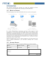
The following figure shows how the Simulink and Orocos runtime work together.
In a mixed WindowsLinux environment, the Linux station exports its build environment as a shared folder using the SAMBA software to the Windows client. The Windows client opens this folder and creates or edits the models using Simulink. When ready, the RealTime Workshop is used to generate the code, which is put in the shared folder and compiled into an Orocos component in the Linux environment. Alternatively, you can develop the model in Windows and use a USB stick to transfer the generated code to a Linux station.
When the Simulink software runs in a Linux environment as well, the generated code will be compiled automatically by the RealTime workshop into an Orocos component.
1.2
SOFTWARE VERSIONS
The following software versions are required to follow the steps in this document:
Software
Supported Versions
Notes
Orocos RTT
1.2.x or later
Linux
Document:
Status/Version:
File Location: Page 2 of 9
FMTC
Orocos OCL
0.4.1 or later
Linux
Orocos4Simulink
1.0
Windows/Linux
RealTime Workshop R14, 2006a, 2007b
Windows/Linux
GCC
3.4.x, 4.0.x,4.1.x
Linux
Boost C++
1.32.x, 1.33.x
Linux
The Orocos component must be executed on a Linux platform, the Simulink environment may be run on Linux or Windows.
1.3
INSTALLATION INSTRUCTIONS
1.3.1 Windows
The Windows software can be installed from the Simulink4Orocos.exe setup program. Check if the directory of your Matlab software is correct (default: “C:\Matlab7”) and press ok. A directory “orocos” is added under “MatlabRoot/rtw/c” which contains the Orocos4Simulink module.
Next start Simulink, browse to the “rtw/c/orocos” directory and execute the 'install.m' script. You need to choose a mexC compiler, the default will do. This script also sets the path to the Orocos4Simulink module. If you need to reset this path, run the 'setup.m' script.
Now the 'Orocos4Simulink' library appears in the Library browser of Simulink. This might require a restart of Simulink
1.3.2 Linux
When you develop the model under Windows, you need to copy some files to your Linux workstation where the components will be compiled. Copy from the Windows Matlab directory the directories 'extern', 'rtw' and 'simulink' to the /usr/local/matlab directory. Make sure that you copied the files after you completed the Windows installation. When you upgrade your Matlab version, you must redo the copy or compilation will fail.
In case you have access to a tar.bz2 package with these contents, you need to upack it in the '/usr/local' directory. The package version must match your Matlab version. For example, do as the root user:
# cd /usr/local
# tar xjvf /tmp/matlablinux2006a.tar.bz2
The generated Makefile lateron will look for this '/usr/local/matlab' directory in order to build the Orocos component. In order to change the path to look for, use the Document:
Status/Version:
File Location: Page 3 of 9
FMTC
MATLAB_ROOT Makefile variable (see also below).
Component Development
The Orocos component generated from RealTime Workshop is immediately usable. For advanced users, the generated component can inherit from another component in order to get more features or functions.
1.4
PREPARATION
Before the Orocos component can be created, the component interface must be known. Simulink4Orocos supports Orocos DataFlow ports for data communication and Orocos Properties for configuration. The supported C++/Simulink data types are 'double/real' 'int/int' and 'std::vector<double>/array'.
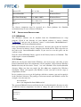
An example interface might look in SysML like:
This component has one input port, two output ports and 2 properties. These elements need to reappear with the same names in the Simulink model.
1.5
SIMULINK MODEL
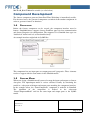
When you design a Simulink model you need to map the inputs and outputs to Orocos data ports. The input/output model is easiest validated visually by containing the model in a subsystem with input and output ports matching the component interface. In the example below, the “SomeComponent” component is modeled in Simulink. The algorithm of the component is defined in the subsystem “SomeComponentModel” and has the same input and output ports as the SysML model. Document:
Status/Version:
File Location: Page 4 of 9
FMTC
The subsystem is connected with the Orocos4Simulink blocks found in the Simulink Library Browser. You need to change the names of the blocks to match the names of the component model. 1.6
SPECIFYING A COMPONENT BASE CLASS
This step is optional.
In order to provide your Simulink model with a C++ base class, you need to add a “Model Header” block to the model. It can be found in the Library Browser under “RealTime Workshop” > “Custom Code”. We have renamed the block to “SomeComponent” and added the following two lines to the block's “Top of Model Header”:
#define BASEHEADER “SomeComponentBase.hpp”
#define BASECLASS Example::SomeComponentBase
The first line states which header file to use for this model. The second line states the full name (namespace + class name) of the class defined in that header. If one of both is wrong, compilation of the component will fail and the model needs to be fixed and regenerated. Note that BASEHEADER has quotes and BASECLASS doesn't.1
If you didn't write such a base class, you may omit this block and the 1 You may also use directory names or use <...> instead of “...” for the BASE_HEADER define.
Document:
Status/Version:
File Location: Page 5 of 9
FMTC
RTT::TaskContext will be used as BASECLASS and <rtt/TaskContext.hpp> will be used as BASEHEADER.
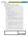
Communicating with the Model
For each model, you may need to create a class which has a compatible interface. For the communicating with the SomeComponent model above, you need to write:
#include <rtt/TaskContext.hpp>
#include <rtt/DataPort.hpp>
using namespace RTT;
namespace Example
{
class ModelUser
: public TaskContext
{
protected:
/** Identical to model */
DataPort<double> m_in_port;
DataPort<double> m_out_port;
DataPort< std::vector<double> > m_monitor;
public:
/** Constructor – initialise interface members */
ModelUser(const std::string name)
: TaskContext(name, PreOperational),
m_in_port(“Input”),
m_out_port(“Output”),
m_monitor(“Monitor”)
{
/** Register interface members */
this->ports()->addPort(&m_in_port, “Data for model.” );
this->ports()->addPort(&m_out_port,“Data from model.”);
this->ports()->addPort(&m_monitor,“Monitoring
values.” );
}
bool configureHook()
{
// Connecting ports can also be done using the XML
// file of the Deployment Component.
TaskContext* model = this->getPeer("SomeComponent");
if (model)
return connectPorts(model, this);
log(Warning) <<"Model not found !" <<endlog();
return false;
}
};
void updateHook()
{
m_in_port.Set( 3.0 ); //write to "Input" of model
m_out_port.Get(); // read from "Output" of model
}
}
Document:
Status/Version:
File Location: Page 6 of 9
FMTC
The C++ class is built using a consistent pattern. For data port, add a member variable in the class body. The name of the member variable can be chosen freely. For each member variable, initialise it with a name in the class constructor. Finally add it to the ports() interface.
This example uses configureHook() to find the model and connect it's ports to the model ports (the model must be added as peer to this component). This is equivalent to using the DeploymentComponent for connecting ports. The updateHook() function can then read and write the connected ports and communicate with the model.
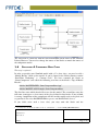
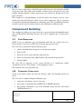
Component Building
The component is built in two steps. First code is generated from the Simulink model, using the RealTime Workshop. Second, the code is compiled into a Linux shared library.
1.7
CODE GENERATION
NOTE: If you use Windows, put your Simulink model file on a shared drive of a Linux station or you'll need a USB stick to transfer the generated code.
The code can be generated using the following steps:
1. Open a Simulink model designed as in the previous chapter.
2. Type 'CtrlE'
3. Select the 'orocos' target from the dropdown list
4. Select any fixed step solver (not variable step) from the dropdown list
5. Click on 'Build'
The code will be generated in the current directory in a subdirectory named “modelname_orocos”. For example: “somecomponent_orocos”.
This concludes the code generation step.
1.8
COMPONENT COMPILATION
Switch to the Linux station and enter the directory where the Simulink model was stored.
The code can be compiled using the following steps:
1. cd into the “modelname_orocos” directory
2. issue 'make f modelname.mk DOROCOS_TARGET=gnulinux'
3. the resulting component is put in the Simulink model directory and named “RTWmodelname.so”
Document:
Status/Version:
File Location: Page 7 of 9
FMTC
In step 2, one can also specify the compiler using classic make conventions. For example: 'make f modelname.mk CC=gcc3.4 CXX=g++3.4 DOROCOS_TARGET=gnulinux'. Other variables can be overriden as well in the same manner. Most important are:
Variable
Default
Description
MATLAB_ROOT
/usr/local/matlab
Specify the path where you extracted the Linux matlab package.
OROPATH
/usr/local
Specify the path where you installed Orocos RTT and OCL.
USER_INCLUDES
<empty>
Add additional include paths. Normally not needed.
COMPONENT
../RTW$(MODEL).so Override the name of the resulting component library.
OROCOS_TARGET gnulinux
1.9
Specify your RTOS flavour: gnulinux, lxrt, xenomai
COMPONENT DEPLOYMENT
Deployment means: creating and configuring the component in an application, such that it becomes ready for operation. You should do this using the deployment component. We refer to the “Deployment Comonent Manual” for instructions on how to load this component dynamically into an Orocos application. The component type of the library is “RTW::modelname”.
Runtime Component Behaviour
Once the component is loaded into an application, it must be configured before it can be used. By default, the component configures itself during construction with the default values of the model.
1.10 EXECUTION RATE (FREQUENCY)
When the component is created, it configures itself using the execution rate set in the Simulink model.
In order to change the execution rate afterwards, you need to assign an RTT::PeriodicActivity object to the component, which will execute the model. After this assignment, you must call the configure() method of the component such that it can check the new rate. If you fail to do so, the component will detect the descrepancy and refuse to start().
Document:
Status/Version:
File Location: Page 8 of 9
FMTC
It is advised to test the used rate first in the Simulink model, as lower rates may lead to less accurate models.
Document:
Status/Version:
File Location: Page 9 of 9
FMTC