1
4.2.5. Main Menu: Sensor Alarm Setup
This selection requires PROGRAM-password clearance (see section 4.2 Host Menu Operation).
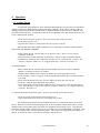
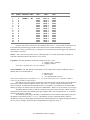
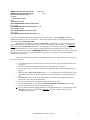
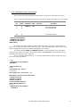
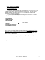
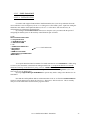
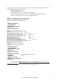
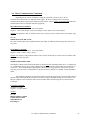
Item ‘5’ of the main menu displays the Alarm Setup Table for models with option ‘Al’. For example:
Slot
No.
0
1
2
Log
Enable
1
0
0
Sensor
Command Label
1A1M0! /1
HG
1A2M0! /1
WT
UPPER
Trip Value
>+23.40
Actions
do/E1
LOWER
Trip Value
<+23.39
Actions
do/D1
- No Alarm Functions
- No Alarm Functions
.
.
.
15
0
- No Alarm Functions
---SENSOR ALARM SETUP--1 ADD/EDIT Alarm Function
2 CLEAR Log Slot Alarms
M Main Menu
Note that the first four columns are identical as that in the Sensor Log Table. In fact, the Alarm
Setup Table is simply an extension of the Sensor Log Table. The former displays the alarm functions, if any,
that are configured for all sensors as defined in the rightmost four columns.
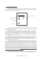
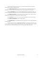
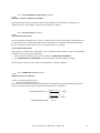
The columns entitled UPPER and LOWER Trip Value are used to define the values at which the
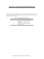
alarms are to be activated (see Figure 1 below) whereas those entitled Actions are used to define what is to
take place when either trip value is surpassed.
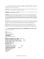
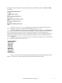
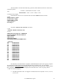
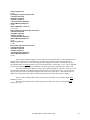
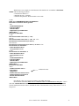
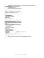
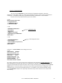
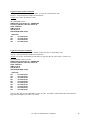
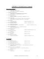
The user configures alarms with item ‘1’. To add an alarm to slot#0 as shown in the Alarm Setup
Table above proceed as follows:
1<CR>
---SENSOR SLOT ALLOCATION--HG=0,WT=1,
Select Log Slot 0-15
0<CR>
Enter UPPER Trip > value +0
+23.40<CR>
Enter UPPER Trip > value +23.40 <CR>
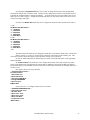
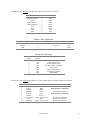
Enter Upper Trip Actions (4 max.) No Actions
0 No Action/Proceed
D Disable Log Slot #
E Enable Log Slot #
C Activate Control Response
M Send Message Response
E<CR>
---SENSOR SLOT ALLOCATION--HG=0,WT=1,
4.2.5 Main Menu: Sensor Alarm Setup
23