1
ALTERATTONS
I
IvloDELs
]ED
]IT
A
SIITTCH HAS BEEN
DETECTOR.
SWTTCHTNG FOR THE
/OTCED STGNATS. EVEN WHEN
TED TO THE VOCODER THE
]ED SYNTHESTS ACTTON.
IR THE A¡4BER VOTCED LED.
BEFORE SWTTCHTNG ON CHECK
REQUTREMENTS:
AT RTGHT HAND SIDE OT EECXMÀTNS
PANEL SLOT HAS BEEN
PROVTDED GTVTNG ACCESS
iO-'r"IEr¡¡S SELECTOR SWITCH.
SYNTOVOX
22I
MANUAL
I NDEX
221 .01/t41
GENERAL DESCRIPTION
D2/¡tZ
D3/t13
APPLICATIONS
CHECK L I SÏ
M4
Ir5
U/ARRANTY
FIRSÏ TIME
OPERATION
H6
t4l
SIMPLI FIED ELOCK DIAGRAM
MECHAN I CAL CONSTRUCT
WIRING CONNECTIONS
EXAHPLES/MATR
I
X
I ON
OPTRAT I ON
/M8
D5/H9
D4
M10
Mlt
t412
Mt
TECHN I CAL DATA
I'/e resez'üe the right to change speeifications u)ithout notice.
ALterations uiLL onLy be nade in the interest of improuing
ouz, products.
221 .D0/t40
l
,J
GENERAL DESCR I PT
I ON
ANALYZER
Syntovox 221 basically consists of a 20-channel audio analyzer,
synthes i zer, and a conErol system.
The analyzer section contains 20 specially designed l'ilters,
accurately tuned and trinrmed for center frequency, bandr,v¡dlth,
gain and Flatness. Center frequencies have epproxímately li4
octave spacing, the fi ìter at the low end of the audio range
being a ìovr pass fi ì ter, and the fi I ter at the high end being
a high pass filter. Filters in betr¡¡een are bandpass filters.
This design provides a precise anaìysis of the audio spectrum
between approximately 30 Hz and l6 kHz. Within a dynamic range
of 60 dB, trequencies in a complex audio s ignaì can be detected
and converted int<¡ controì vol tages, which are fed to a rovr of
20 LEDs, dísplaying the energy in each frequency band. The analyzer is located in the upper part of Syntovox 221, constructed
on ê seDarate Drinted circuít board.
The 20 control vol tðqe outputs of the analyzer are directed to
a 20x20 matrix svsleil and to the muìtiwav connector at the back
paneì of Syntovox 221. These outputs have a range of 0...5V and
can be used to conr-rol external devices. For computer appl ications a 20 channel mul tiolexed AD converter shôuld be used to
be able to store audio anal'¡ses.
SYNTHES I ZER
The 20-channel synthesizer is also composed of one lcw pass and
identical to the
one highpass filter and 18 band pass filters,
anaìyzer. The synthesis fílter bank has one audio input and one
audio output. Each of.the 20 f ílters is foìlov¡ed by a modulator
with a control voltage input 'nrhose sensitivity can be adjusted
by means of the potentiometers in the bottom row of Syntovox 221.
These aItenuators are numbered 1...20 and are routed to the correspondinq matrix columns and the control vol tage inputs at the
back panel mul t iv/ay connector. The amount of contrcl vol tage fed
[o the synthesizer rnodulators can be monitored by means of ihe
LEDs
near the control knobs.
MATR I X
The control connections betr^reen analyzer and synllresizer are mad¡
via the 20 x 20 matrix system. Any controì voìtage output can l-.e
patched to any control vol tage input, Timbre can be chanEed easì ì ¡
by shif tinq all anaìysis information up or dovrn the synthesis
f ilter bank.
In the norm¿l mode al I anaìyzer control outputs are connected to
corresponding synthesizer controì inputs with the rnatrix pins in
the d iago:ra I pos it ion f ron Ihe L]pper lef E corner to the bottom
right corner.
A signal appì ied to the audio input ofl the synthesizer wi I I be
shaped according to the signal which is being exarnined in ':.he
analyzer section.
221.)l
/Ì'il
It is uery important to understand that in this z.espect the uoeoder acts as a moduLatoz, alñch úntposes the characteristics of one
audic s')gnaL upon another au.d'Lo sígnaL. So, ii speech is applied
to the anaLyzer input, the inteLLngibiLity chanacteristias are
imposecl upon únA other signaL, fed ínto the synthesizer, prouidecl
that sigrtaL L:loes conbain a reasonable amount of harmon't cs - it
uiLL not uork on a sine uaue!
CONTROL SYSTEM
Since speech is a composite oF voiced sounds (4,E, l,O,U, etc.),
and unvoiced sounds (sibílants, K,P,T, etc.), a detection system
to d iscriminate these phenomena is necessary. l./hen Syntovox 221
is used for speech synthesis Èhis voiced/unvoiced detector feeds
noise to the synthesis fi I ter bank when a sibi lant is detected,
and s imu I taneous I y the replacement sound at the synthes i zer i nput
ís cut of t.
Voiced and unvoiced decisions can be used for Eriggering external
devices, and it is also pos5ible to control the operation,of the
voiced/unvoiced deEector external ly. In Ehat case the lNHlBlT control should be used to bìock the internal circuit which normaì ly
drives the detector. Control inputs and outputs are avai lable at
the mu I t ir^¿ay connec cor a t the back oane I .
INTERNAL PULSE
IiI
+
Çr
rt
GENERATOR
Syntovox 221 is equipp.ed with a pulse generator for simple but
effectíve speech synthe.sis. This pulse generator is voltage control ìed andcan be modulated external ly, oF with the bui lt-in low
frequency control osci I lator and random generator.
The low Frequency control osci I lator can be used to introduce a
vibrato whose speed and depth can be control I ed.
The random generator has two outputs to control the pul se frequency. 0ne of the outputs generates a stepl íke change of frequency each time a short interval in the speech signal is detected; (Sffe¡. A very low freguency random signal is avai lable to
create a continuously changing pitch; (vlr).
EXTERNAL SOUND SOURCIS
External sound sources can be modulated by the analyzer input
s ígnal as iveì I . Both UNVOICED and V0 | CED paths i n Syntovox 221
have a separðte input (B and C respec t i ve I y) for app ì y i ng sound
material to the synthesis f il ter bank, other than the internal ly
generð ted pu ì se and no i se.
221
.D2
/t47-
FILL-IN
CONTROL
control was designed for special speech synthesis
purposes. When a replacement sound is to be modulated with
speech, for instance, â signal only wí | ì appear at the output
of Syntovox 221 when there i s i nformat ion from the ana I ys i s
fi lter bank. The FILL-lN control is meant ro fi I ì rhe gaps
between spoken words by automaticaìly tading-in the replacement sound, so that the origín and character of the replacemenl soundrvill not be obscured. lmmediateìy this replacement
sound wi I I be faded out when speech is appl ied to the analyzerThe amount oF FILL-lN can be controlled with a potentiometer.
The FILL-lN
CLEANFIED
Next to the analyzer input attenuator two controls labeììed
SYNTH and CLEANFEED are s i tuated
The CLEANFEED control is a direct feed from (speech) input
to output, and the sYNTH controì feeds the i nput s igna I d i rectìy to the synthesis fi lter bank. This faci I ity offers very
ínteresting possibi I ities when instead of speech the signar
of a music synthesizer is processed via Ehe analyzer input.
By exclusively Feeding noise to both voiced and unvoicecr sections, the s-ound of the music synthesizer will be enriched
with additional harmonics, selectively f iltered out of pink
_
noise.
APPLTCATTONS
An<zLyzing speech;
Synthesizing speech;
Phonetic researeh;
FormanL
shifting;
Imposing speech upon sounds of mechanícaL deuices, u).tnd, sea.,
cries of anímaLs, etc.;
fmpo.síng speech upon sôunds of rmtsíca.L ínstrwnents, chairs,
orchestras etc.;
fmposírtg speech upon other human uoíces;
ALtermating tunbre of insttunents;
fmposíng chatacterístics of one instrunent upon another one;
Addíng h,:.rnoníc and non-Vtarmaniè otertones to instr¿ments;
Geneyattng speech (aomputer interface opbiona.L) ;
Spoken instructíone to aornputens (.interface optí.onaL) ;
ControLLing syrtthesizens and other uolt<zge controlled uníts.
221 .D3/t43
j
q
il
t
t_
CHECK L I ST
Aftex unpackirq and before pLugging ín Sgntotto.æ 221 it
uâefuL tò eheck the contents of the aceornpanging smaLL
uhích should eontain foLlouting items:
I
LA
A^-
mains chord
I spare fuse, 1A/slow blow
1 56-way multiconnector
22 natrix programming pins (2 spare pins)
4
seì
It is
f
adhes
ive plast ic feet (for free-stand i ng use of
adoísed
to
foLLot't carefuLLg the
FLRST TIIûE )PERAIION
221
.t4\
in thís manuaL.
ínstructions
uni
undex
t)
--¡
L
r
I
\
-J
L
I
t
I./ARRANTY
r
q
I
'4
q
t.,j
t
1
IJ
tr
rr
L.
.t
\
-
I
F¿
3
I
Ihis
uaz,z,antg cotsers pa-rts and Labouz, fon 1 year
fz,om d.ate
ptnchase:
claíms uiLL be rejected uhen the unít has been mísused,
nisaQiusted, modífíed oz, repai,ed by unauthorised. pez'sâneL.
Ilot couez'ed by the .uaz,z'anty ate mechanicaL parts (Zuífuhes,
connectot,s, potentíometers) and LEDI.
carniage to and f,om synton ELectronics B.v. is to be paíd
of
by the
r''¿
\
t^
t
\
T
¡:
tJ
oLmer.
T.hís uaz'r'anty is,u,aLid onLg
is not transfez,abLe.
221 .ì45
to the oz,ígínal
purehasez. anã.
PIRST TIME OPERATION
t.
DO NOT ALTER CONTROL SETTINGS:
Theg haue been factony-set fon g quiek step bg step statting
sequence. The smaLl knobs in the bottom rou shouLd be at
maæírmtm, aLL othen knobs (PL-P16) at zero.
Numbers
of
contz,oL potenti,ometers
SUppLy (zz0 vnc
refen to block diagrøt
+ l0B -50/60ïz)
2.
CHECK MATNS
3.
CONNECT THE OUTPUT OF SYNTOVOX 221 TO A POT./IR AMPLIFIER. AND
CONNECT A LOI,J IHPEDANCE (IO...6OO OH¡IS) ¡IICNOPHONE TO M¡C INP@
Fon
4.
uiring connections
PLUG
see page M10.
R
790 Hz
MATRIX PINS, DIAGONALLY FROM UPPER LEFT CORNER
IGHT CORNER.
is
nou connected
to
ehanneL
L,
2J0 Hz
SEE.PAGES T411-13 FOR CONNECT USE OF I,I¿.TRLX.
lr
5.
TURN UP CoNTRoL
rhe
'l
6.
*!
\
J
2, ete.
.
detectot ean be checked by saying
sLouLy
TURN
Up CONTRoLS p16 (O/p LEvrr_) AND p3 (Clen¡lrre o)
.
Be carefuL: accoustic feedbaek may occur! check if microphone
sigrøL comes thz,ough. rf not, eheck again fon z,ight connlections
(M10) and/or contz,oL settings.
-J
t
channeL
reduce gain.
J
l
1 (n¡¡nlyzrn)
to
TO
into the míez.ophone. The ,Srtrt,Ttr, -or¿ iryi uiLL eâuse
the ønber LED undez, uNV7lcED to Light uþ, and the othet, sound.s
uiLL trigger the VOICED LED.
hhen the red LED neæt to the ANALTzER controL pl Lights up,
J
-J
P
v1rcED/uNV)rcED
t,SyNTOV1Xu
t1
'(l
AND SWTTCH ON.
IN 20
LOI./ER
,J
D4.MB.
7.
SET P3 (CIrNHrrrO) BACK TO ZERO AND TURN UP CONTROL P7 (VCO) rO
APPROX.
OF SCALE. DO THE SA¡,IE I./ITH CONTROL P14 (SYrurHrSiS).
TURN UP SLOI./LY P9 (ENTSTT) AND KEEP TURN ING WH ILE TALKING INTO
THE M I CROPHONE.
3/\
I
ìI
J
T
I
J
r3u uiLL heaz' gour synthesized ooiee raíse in pitch uhiLe tw,ning the vc) PRESET contz.ol. At higher frequenà"" inteLLigibiLitg deteníorates, due to ,the facl tha't måú of the annLy"zer
information uiLL be in a Louei
speetzwm than the synthes-ized
pítch,
:
I
Èi
Jt
I
ÏF
YOU LTSTEN CAREFULLY YOU WNL NOTTCE THE LACK OF STBTLANTS
TN IOUR SYNTHESIZED SPEECH:
221 .¡16
e:
I
8.
TURN
up
coNTRoL
p5
Nou aLL esses anã.
hou
9,
sr)
|
N sEcr | 0N
uNVo I cED.
other unuoieed sourlås uiLL appear. Notiee
inteLLigíbiLity
SET C0NTRoL
(Ho t
irnpnouee
!
p7 (VCo) T0 ZERO, AND TURN Up CoNTROL pg (¡rOlSr).
Nou yotæ uoiee uíLL be synthesized mereLy from noise. whispexing
into the miez,ophone uiLL be synthesized DerA accurateLy by
syMTov2x 22L.
i
10.
OF
I
:t
il!.
IV
l{^
A qUICK LED DISPLAY CHECK CAN BE DONE BY MAKING HISSING
'
D
SOUNDS
IFFERENT ''COLOURS'I.
rou uiLL obsense thnt the LEDI dispLay the ehanging of peaks ín
the spectnum at the high end of the audío ?ange.
voieed sounds of different pitch uiLL eause the LEDI in the
Louen end of the audio ?ange to Light up. ALso you uiLL notice
that speeific LEDs Li.ght up ü¿th specífie uoíced sounds.
Tz.y A, E, f , O, U etc.
,J
;l
-l
_,'
*(\
This concludes a first try out of the unit. lt is important to
have the block diagram ar hand when working wirh syNT0vox zz1,
since it il lustrates clearly al I control functions.
For more information abouf operating the matrix
read secr ion EXAMpLES (Ul l - t ¡)
¡
I
I
Ll¡
r-r_
Lg
L
l:
SyNTovox
zzl,
NB: srNCE THE svNTHESrs FTLTER BAttK ourpur (p14) AND rHE FrLL-ril
CONTROL (P1-5) ARE FED TO THE OUTPUT MTXER OF WHTCH P16 TS THE
MASTER CONTROL, IT TS ESSENTTAL THAT THIS CONTROL IS OPENED ALL
THE TIME, h/HEN THE UNIT IS IN OPERATION.
3-_
-.d
of
221 .t47
¡
ñ
Ei
$
q
n^ \
=r
:t
rl
¡¡ \-/
H
g
I
t:
d
N
tu
z
j
åfr
>I
ol-
J
|l
r
t¡¡
x
N
¡.-".J
r
fI
ì
{
z
(
;f,ir
k
I
ZE
l-.
ìl
fq,
[6
f
IH
t-
o
.E
E¿fi
g'E
o
1
,J
-l
r
0
tO
H6 16
z
u¡
u¡
(o
o
ul
J
(tl
ut
t¡¡
0tl
@
0
l¡¡
'9
,86 [g
0
l¡,1
0
õ
o
z
l
ig ìg
ô.
\/no
qõrõ
ng
u¡
z;
:1
lrJ
înZ
JUJ
lo
=l
o
-]
o:
(
tr
u
(
-r
ro
o
r-l
-t
F
J
(l
o
I
Þl
\-,
-.-L
u¡
f,l
0l
zl
1
l¡¡
r
q,
t¡¡
o
z
(
r
I
N
F
0
0
0.
(
|l
z
II
Ëo
I
I
fn
5v
ru tt
ilð
XO
o
ul
õ
I
E
ul
t-
r-l
o
ol
I
z
ll
zl
¡
Qo
óH
r-j
i3
rnñ
q
I
t
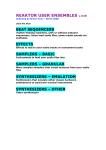
MECHAN I
CAL CONSTRUCT I ON
'l
Ì
rÉ
i
I
!
supply voìtage
doubìe sided pcb for i nterconnecting al I c i rcu its
and matrix;
pcb 221.06
stabilizer;
pcb
i.E
221 .0J
pcb 221 .02
voiced/unvoiced
detector;
I
il
id
innrrt rirruitq'
i
3fi
J
-Lf,
î'l'.¡
I
ilú-'i
ì
;td
[Lr
1ì
l¡
J
ïrri
*5
56-way
multiconnec to r
t¡
fiìl-in
ôrrtñrrt
^l-ì
#
synthes izer board pcb 221 .011
pcb 22 I .03; conta i ns
pul se generator, ì fo,
no i se,/random generator,
circuit
r irr¡r
and
ilc.
back paneì with pcb
221 .08
power suppìy and
LED
-l!!
stabil izer;
connector f i ts
to pcb 221.05;
f-¡
rl
l1
il
,g
except for screened
leads to input and
output XLRs: no wiring
involved!
||
\tt¡
;il
H
!6-way multiconnec tor
aå
back
pane
I
vrith inputs
.i
and outpuE
XLRs;
mains connector,
fuse and mains
srv i Ich;
,:l
I
.J
pcb 221 .06 for
multiway
connector
4
-tt
¡t
J
I
J
-j
J
221 .D5/t4g
rì
q
t,
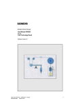
XLR WIRING CONNECTIONS
1
}J
t--
=
o
Þco
a.c
ou('l
trnc ø
[[tl
-Nrvr
=
u
L 'El
'- q)
U+J
U
a+JG)cfE
\¿ L +,
ooo
lo-c
F Ø O-
O1J
.- O-CO
E+J!
o:t
c Oo
-U.lJ-
cc:o
=ac
OOs'
L.-
ô
L!¡
(J
L
Oì O)
o
Ln
il[n
E
J
cct
o
o
FC{tr
1JE
cc -o
o)
OO
t- L..-
ô
t^l
(J
gl o)
o
ililtl
z.
=
r/)
F
(\¡
a\
-Y
-o
o
(\^
-tlE-
cco
l¡J
^
t<l
\_.7
J
=
F
=
o-
z.
I
(-)
l¡J
laJ
otll
(J
=
22l.Hl0
ff,c
OOqt
L t-.(D Ct, ø
nil[
-Nrrt
E-coo
f,EC
O ('tgl
O)(n t,
ll [[
È(\¡O
l^t
E
-v
o
O
u
r\!
vd)
(:jo+JE
O tr
\o o
I F
o o
l.r\ -o
¡J.-III
J Ul-o
O-C
E oO
.- r,f' v)
|¡H ,i
I
't.
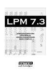
EXAMPLES/MATR I X OPERATI ON
In this section only a few of the numerous possibil ¡ties of
programming the matrix can be given.
The small knobs in the bottom röw, numbered 1...20 are also
important in al I appì ications, since they can attenuate the
control voltages fed to the synthesizer inputs.
Changing these control voltages has the effect of processing
the sound through a channel equalizer, which can be used very
effectively in almost all applications.
The
way
first example given below states the right and the wrong
to use the matrix. PINS SHOULD NEVER BE PUT lNTO THE SAME
\./ILL CONNECT OUTPUTS OF THE ANALYZER
P0lNT. Nothing will be damaged, but it is totally impractical and it may cause unwanted side effects.
VERTICAL COLUMN. THIS
T0
ONE
,
h
ili.
il
0UTPUT
3\0 Hz I S
CONNECTED
TO
I NPUTS
ït
ü
3/\/5/6.
T5
CONNECT MORE I NPUTS
1t
TO ONE OUTPUT.
tlj
IT
S0METTMES
CAN BE USEFUI TO
ooooooo )oc
foooooooooooooooo )oo
co ooo ooooo
x
ï
J
t
ri
J¡
I
f,ooooooooooooo ooo )oo
f,ococooooooooooo,o )oo
3000000o000000000 )oc
300 00000000000000 )oc
fo oooooooo oooo oo o )Õ^a
f,oooooooooooooooo( >õd
f,ooooooooooooooo< )o C
f,oo oooo oooo ooo oool >ç.tT
J \.i \J L,' \J L/ W \J \J I.J \J U \J U \J ! (J JU\J
foooooooooooooooo )oc
fooooooooooooo ooo
f oo oooo oooo ooo ooo ioc
foooooooooooooooo )oo
coooooooooooooooo )oc
foooooooooooooooo
)oooooooooo ooo ooo )oc
fooo ooo o ooo oooo oo )oo
loôooooôooc)ôôôôÕô
ì a'ìô
1 g
E z
J
Îc'
't
I
J
-r
4
t!
I
¿
D22t.Mt
I
11 13 ltt iiis
E¡YNÎHEAIZEFI
1
lEo
230
E!Elc¡
t
o
FI
3rlo M
41c,
4E¡c'
E¡9c¡
E¡Ac¡
A
N
A
L
Y
E
1k3
1k€¡
rkg
2k3
2ka
3k4
qkr
4KE¡
Ek9
zk1
221
MATFIIX
t/RoNG
I
OUTPUTS
590/
710/880/1kl
1k3 Hz C0NNECTED
TO ONE INPUT (I6)
looooooooooooooooooo
)aoooooooooooooooooo
)ooooooooooooo oooooo
SOOOOOOOOOO OOO OQ,OO OO
30o 0aoo oooo ooooooooc
coo ooooooooooooooooc
t
FI
eao o
13E7911131!'1719
Tc' SYNTHESIZEFI
1k1
E¡
Tc, E¡YNTHEAIZEFT
t
fooooooooooooooooooo
ti
ti
il
n
J
,
t
'rå
:
l
t'
n,
DOOOOOOO OOOO OO OOOO OO
:
F
FI
c'
M
A
N
A
L
Y
z
E
FI
qnd.
Set aLL contt'oLs to
zero, eæcept P7, PL4 tL
P16. Then turn up P2 t
and Listen hou gour
anaLgzed uoiee is
pz,ocessed through
bank.
Iry this aLso uith
Ena
rmtsieaL instrwnent
nt
ut
atINPUTA-LINE,
noise to ssanthesizen üith P8.
and. add
Eætz,a hannonics ui
tiLLL
be added to the so
sound
of the instrumenþ,
This faciLitg uork
rks
out ueny fine forT
organs, synthesíze
zeTS
and Fend.er pianos.
7k1
??1
EX. NR 2
MATFIIX
tt
ôTrnanT; gn1,tT-7.
ox eon 7
settíngs and" List
isten
hou gour uoíce ui
UUUb
See
1S¡O
23C¡
ooooo oooo ooo oo c
cooooo o oo ooooo oo ooo c
300 00 000 000000 00000c E¡AO
30000000000000 00000c 1k1
3000000 00000 00 0000 0c 1k3
cooooo ooo ooo oo ooooo c 1k6
foooooo oooo o oo ooooo c 1kg
cooooooooooooooooooc ak3
foo oooo oooooo o ooo ooc eka
cooooooooooooooooooc 3k4
coo oooooooo ooo o oo ooc ekr
cooooooooooooo ooo o oc ¿ks
cooooooo ooo ooooooa oc E¡kE|
O OO OÔO O ô ÕC)ô ôôô ôr.lrì ô lrr
221 .ì412
Repeat First Tine
}pez,atíon anà use
a.Lao yJ.u and. Hll
the synthesís fiLter
F
FI
o
M
A
N
A
5Ecl L
71cJ Y
3 E¡ 7Cl1113161718¡
TO EIYNTHEAIZEH
A.
Then txg P12
2ã¿1
MAÎFIIX
foooo ooo ooo ooo ooo ooo eBo
300 0 0000000 000 00,o o oo 34c¡
f,oo ooooooooooooooooc 41c¡
f,oo ooooo ooo oo o ooo ooc 4'9cl
f,oooo
1
t4^-hâ
l4+.t
uuguYeuuv!|.
P1-3.
7k1
f,ooooooooooooo ooo oo c E90
3000000 00 0000000000c 71c¡
cooooooooooooooooooo E|BC'
300 0000 0000 000 000 000 1kr
30000000000000 00000c 1k3
30000000000000 000000 rkÊ
foooooo ooooooo oooooo 1k9
foooooooooo ooo ooooo o 2k3
)oooooo oooooo o ooo oo o eka
cooooooooooooooooo oo 3k4
30000000000 000000 000 4k1
foooooooooo ooooooooo 4kEl
)oooooooooo oooo ooo oo 5ke
guarantees best inte
for uibrato effeets.
Kg
SOOOOOOoOOO OOO OO,OO OO
f,oo oo oooooo ooo o o oo oc 41c,
fooooooooooooooooooc .rE o
fooooooooooooôooôôôô
l gE:zstrig¡a,tz.tg
FI
1k3
1k6
1k9
ek3
eka
3k4
akt
¿kg
1E¡cl
f,oooooooooooooooo ooo El3cl
fooooooooooooooooooo 2AO
foo oo ooo ooo ooo ooo ooo 34Cl
I
ttNor¡naL modett patch;
f'h1,5 mAt?Læ roLteLng
34C¡ M
41C' A
N
4Ac¡ A
E Élo
L
710 Y
co oooooo oooooo ooooo c
coo oooo oooooooooooo c
coo oo ooo o oo ooo oooo oc aao zE
cooooooooooooo oooooc
cooooooooooooooooooc
oooooooooooooooooooc
co ooooooooo o oo oooooc
o oo oooo oooo ooo oooooc
oooooooooooooooooooc
oooooooooooooooooooc
ooooooooooooooooaooc
ooooooooooo ooo oooo oc
ooooooooooo
ooooooo oc
oôôooooô ooô ôôô ôr)ôr'l r-la
EX. NR I
19Cl
fl3E¡
z
E
FI
7k1
221
Mannr>t
be
ttDonald-Duckea
kedt'.
Shifting the pine
ins
to the right aiLl
more
make the effect
stz,onger.
Shifts more than
L90-5, 230-6 etc.
uiLL seoere intel
LisibiLity.
ALso trg this on
tmtsicaL insttaner,
nlments,
and. shift pins tc
Dne o'neT, d-LrectLLOn.
ut
EX. NR
t
FI
C,
|\/|
A
N
4eo A
EEO L
71C, Y
BEC¡
1k1
1k3
1k6
z
E
F
1ke
Pk3
3
'tInüerae mode" Patch;
thie is not
uenY
pnactícabLe for sPeech
syntheeíe purPoses, sinee
the effeet uiLL be aLmost
uninteLLigibLe.
HoüeÐen, it can make
uery interesting effects
on ¡mtsieaL insttwnents.
LINE, P7, P2,
P74, P16, and íf uanted
D. INPUT-A
ekB
3k4
4k1
4ks
DQ
EKB
9 11 13 1l¡ 17 19
æ,
7k1
221
MATFIIX
Tcl BYNTHEC¡IZEFI
EX. NR 4
FI
This patch is fon PartLY
inuersing forTnant areal -
E
MfC INPUT A; P7' P5, P7'
(P12/L3 ) P1-4, P1-6 .
F
c'
M
A
N
A
tEo L
71c¡ Y
z
E|BO
1k1
1k3
oooooooooooooo oooooc
FI
340 and. 490 Hz inuersed,
880 and 7k3 Hz inuetsed,
2k3 and. 2kB Hz inuersed.
rk6
1ks
ekå
ekB
3k4
4k1
4kEl
ske
r
=E-
e 11 13 16 17 lcl
TCl SYNTHEE¡IZEH
USE
0F
I
NPUTS
B and
7k1
221
MATFIIX
C
These inputs an'e used uhen
the internaL puLse generaton and the othen
the unuoiced
etc. )ard
imposing speech upon these repLaeement sounds the FLLL-IN contnol
eai be u-sefuL to ínproue continuity of the sound effeet.
When
p15
221 .t413
ru.r*,ioL
DArA
20 CHANNELS
1 B band pass filters
1 low pass fílter
t
high pass
filter
54 dB/octave
54 dB/octave
54 dB/octave
20 envelope followers
20 low pass filters
Dynamic range
Control voltageoutputs
20 LEDS (real time analysis read-out)
20 CHANNELS
18 band pass filters
filter
t high pass filter
1 low pass
18 dB/octave
60 dB tYPical
0...+5 V
54 dB/octave
54 dB/octave
54 dB/octave
20 voltage controlled amplifiers
VCA dynamic range
Filter signal to noise ratio
VOICED replacement signal break-through
SPEECH signal break-through
Control voltage inputs
20 control voltage attenuators
20 LEDs on control voltage inputs
58 dB
74 dB typical
-70 dB typical
-68 dB typical
0...+5 V
10 kOhms impedance
x 20 matrix; 3 mm pitch
20 programming pins
2O
Mic input
Line input
LED overload indicator
SPEECH to SYNTHESIS control
SPEECH to OUTPUT cleanfeed control
600 Ohms, balanced
10 kOhms, unbal.
Line input
LED overload indicator
10 kOhms, unbal.
Line input
LED overload indicator
10 kOhms, unbal.
Voltage controlled pulse generator (VCO)
VCO - total range
Low frequency control oscillator
Pink noise generator
Random VLF generator
Random step generator
VOICED/UNVOICED detector with LED status
ind icators
Fill-in control
16 ... 500 Hz preset
16... 16 kHz
0.05 ... '10 Hz typical
56-way mu lticonnector for external
control applications (computer interface)
20 analyzer control voltage outputs
20 synthesizer control voltage inputs
VOICED/UNVOlCEDcontrolinputs/outputs 5Vlogic
lNHlBlT
control
VCO control input
All inputs and outputs fully protected
Cannon/XLR connectors on inputs and output
Mains connector, mains switch and fuse
Power requirements
Dimensions
Weight
5V logic
1V/octave;0.,.10V
1A (slow)
220 V AC
483
t
109" 50/60 Hz
x 178 x 184
6.5 kg
SPECIFICATtONS SUB,IECT TO CHANGE WTTHOUT NOTTCE
mm


![ft.757gx ]i hf all mode computer aided transceiver](http://vs1.manualzilla.com/store/data/005735092_1-f8362b9c1e3279439f07a335507c2c8e-150x150.png)