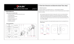
1
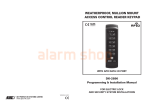
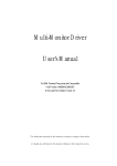
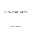
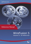
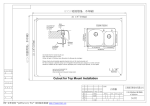
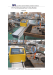
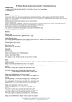
Dear Users:
Thank you for choosing our products.
For your own safety, please read this manual carefully before using.
Please be advised: The manuals are for your reference only. Due to
continuous improvements, we reserve the right to amend the
specifications without prior notice.
1
Contents
1 Product Introduction............................................................................................... 6
1.1 Production Drawings................................................................................... 6
1.1.1 External View.................................................................................... 6
1.1.2 Dimensional.......................................................................................7
1.2 Product Features......................................................................................... 7
1.3 Scope of Application....................................................................................7
1.4 Door Handing............................................................................................... 7
1.5 Technical Parameters..................................................................................8
2 Function....................................................................................................................9
2.1 Unlock Mode.................................................................................................9
2.2 Passage Mode............................................................................................. 9
2.3 Alarm Functions........................................................................................... 9
1) Low Battery Warnings........................................................................... 9
2) Tamper Alarm......................................................................................... 9
3) Wrong Try & Lockout Delay Function................................................. 9
3 Operation & Management................................................................................... 10
3.1 Keypad Operation......................................................................................10
1) Keypad.................................................................................................. 10
2) Password.............................................................................................. 10
3.2 Admin Password Setting...........................................................................11
3.3 Add New User..........................................................................................11
3.4 Delete User.............................................................................................. 11
3.5 Clear All User............................................................................................. 12
3.6 User Permission......................................................................................12
3.7 Emergency Battery................................................................................. 12
3.8 Mechanical Key.......................................................................................13
4 Installation........................................................................................................... 14
4.1 Assembly Drawing..................................................................................... 14
4.2 Hole Dimension..........................................................................................15
4.3 Installation...................................................................................................16
4.3.1 Installation Step.............................................................................. 16
4.3.2 Test the Lock................................................................................... 20
2
4.3.3 Notes for Installation...................................................................... 21
5 Maintenance.......................................................................................................... 22
6 Attachments........................................................................................................... 23
6.1 Attachment 1 Packing List........................................................................23
6.2 Attachment 2 Installation Tools................................................................ 23
3
Important Notes
(1) The smart code lock is a kind of high-tech product, the installation always direct
impacts on the operation and service life of the lock. We strongly recommend
installing the lock by professional person.
(2) To install the lock after room decoration is recommended. That will avoid the lock
surface being damaged and influenced by the wet paint.
(3) After installation and testing, please clear all users information in the lock memory,
then register your own admin password at the first time.
(4) To avoid any inconvenience caused by the flat battery, please replace batteries
upon the low voltage alarming.
(5) If you are going for a long trip or the lock will be unused for a long time, please carry
the keys along with you, and remove the batteries out to ensure the service life of
the lock.
(6) Password Capacity: 36 pieces
(7) Default admin password: 0012345.
(8) Please record all user information and fill in the User List for future use as below:
4
User List
Serial
No
Password
No.
00
19
30
02
01
20
31
03
02
21
32
04
03
22
33
05
04
23
34
06
05
24
35
07
10
25
40
08
11
26
41
09
12
27
42
10
13
28
43
11
14
29
44
12
15
30
45
13
20
31
50
14
21
32
51
15
22
33
52
16
23
34
53
17
24
35
54
18
25
36
55
S/N
User ID
01
Name
Enrollment
Date
5
Name
Enrollment
Date
1 Product Introduction
1.1 Production Drawings
1.1.1 External View
Keypad
Exterior
Assembly
Exterior Lever
Exterior Assembly
Battery Cover
Interior Assembly
Interior Lever
Interior Assembly
6
1.1.2 Dimensional
Front view
Side view
Back view
Side view
1.2 Product Features
Unlock by Password and Mechanical key override;
Robust and Flexible Mechanical Structure with flexible level;
Anti Break-in/Damage Alarm Protection;
Vistor-Friendly with Passage Mode.
1.3 Scope of Application
Perfect for Multi-Family, Apartment, Condominium Housing, Office Building, Government
Building, Bank, Court, Hospital and Warehouse.
1.4 Door Handing
室内
室内
右(内推)开门
左(内推)开门
室内
室内
右(外拉)开门
左(外拉)开门
7
Left-handed door: when you stand outside the door and the fixed hinges are on the left, the
password lock is then defined as left-handed door, which is further divided into left-handed
(push) door and left-handed (pull) door.
Right-handed door: when you stand outside the door and the fixed hinges are on the right,
the password lock is then defined as right hand door, which is further divided into
right-handed (push) door and right-handed (pull) door.
1.5 Technical Parameters
No.
Item
Technical Parameters
1
Static current
≤30μA
2
Dynamic current
≤ 200mA
3
Lifetime of battery
5,000 times to unlock the door
4
Operating voltage
DC6V
5
Power supply
AA Battery
6
Emergency power supply
DC9V
7
Low battery warning
4.8V±0.2V
8
control system
Single circuit
9
Password capacity
36
10
Operating temperature
-10℃~55℃
11
Operating humidity
10%~90%
12
Open door direction
Left handed and right handed
13
Door thickness(mm)
35-80
(Note: Parameters subject to change without prior notice)
8
2 Function
2.1 Unlock Mode
Unlock by Password and Mechanical keys.
2.2 Passage Mode
The switch of the passage mode is on the interior lock body.
When the switch in “ON”, the system is in passage mode, the LED light flashes once every
three seconds. Then the lock can be unlock free with no verification required.
2.3 Alarm Functions
1)
Low Battery Warnings
When the batteries go flat during the unlock, the buzzer will give off warning“beep,
beep……”, Then you should replace batteries immediately.
2)
Tamper Alarm
When the lock be tampered, the buzzer will give off alarm sound of “beep, beep……”.
3)
Wrong Try & Lockout Delay Function
Upon inputting the wrong password consecutively 3 times, the buzzer will give off alarm
sound “beep, beep……” and the keypad will automatically lockout for 15 minutes.
9
3 Operation & Management
3.1 Keypad Operation
1) Keypad
The lock with 7 keys:
0, 1, 2, 3, 4, 5 and OK.
Additional, the key 0, 1and 2 also working as function key after the admin password input:
Key
Function
0
Register New User
1
Delete User
2
Clear All User
2) Password
The password length available from 3~12 digitals. It consists of 2 bytes User ID and a
piece of Password. After input the password and need to press OK to confirm.
User ID should be combined from 0~5, there are 36 pieces User ID in total as following:
00,01,02,03,04,05,
10,11,12,13,14,15,
20,21,22,23,24,25 ,
30,31,32,33,34,35 ,
40,41,42,43,44,45,
50,51,52,53,54,55
“00” is the default Admin User ID.
The User ID start with “5” is one-time password. It will be invalid automatically once after
you use it.
10
3.2 Admin Password Setting
After lock installation, please reset your own Admin Password immediately for security:
1
Open battery cover and remove one battery, slid the switch to “ON”.
2
Press and hold “0” on exterior locks assembly. Then reload the battery;
Beeps “Do re mi...” and LED flashes green.
3
Input “00” + “OK”, Beeps “Do re mi...” and LED flashes green.
4
Input new password (within 10 digitals) + “OK”, Beeps “Do re mi...” and LED
flashes green.
5
Repeat step 4 and set finished
Note: The original admin password will be overwrite by new admin password.
3.3 Add New User
Step as following:
1
Input Admin Password + “OK”, beeps “Do re mi...” and LED flashes green.
2
Input “0”+ “OK”, beeps “Do re mi...” and LED flashes green.
3
Input User ID + “OK”, beeps “Do re mi...” and LED flashes green.
4
Input user password within 10 digit + “OK”, beeps “Do re mi...” and LED flashes
green.
5
Repeat step 4 and set finished.
Note: The User ID composed by 2 digit from 0~5, and should to follow the User List.
3.4
Delete User
Step as following:
1
Input Admin Password + “OK”, beeps “Do re mi...” and LED flashes green.
2
Input “1” + “OK”, beeps “Do re mi...” and LED flashes green.
3
Input User ID + “OK”, beeps “Do re mi...” and LED flashes green.
Delete Success
Note: The Admin Password can’t be deleted.
11
3.5 Clear All User
Step as following:
1
Input Admin Password + “OK”, beeps “Do re mi...” and LED flashes green.
2
Press and hold “2” for 5 seconds,
3
Press “OK”,
4
Clear Success.
LED light flashes red and alarm sounds.
beeps “Do re mi...” and LED flashes green.
Note: The Admin Password still exist after clear operation.
3.6
User Permission
Item
Capacity
User ID
Permission
Admin
Password
1 PC
00
User Password
29 PC
01-45
Unlock the door
One-time
Password
6 PC
50~55
Unlock one time only
Add/Delete User and One-time Password;
Unlock the door
3.7 Emergency Battery
In case of battery depletion, an external 9V battery (6F22 , 9V) could be used as an
emergency power supply. Connect it via power interface at the bottom of the front lock
body to supply power and unlock the door.
Note: Please replace the lock battery immediately after unlocking by emergency battery.
Emergency Battery
12
3.8 Mechanical Key
Each lock has configured 3 pieces of mechanical keys and they can unlock the
door when password failed.
I. Unlock by Mechanical Key
Open the cylinder cover on the exterior level, Insert the mechanical key and turn 90
degrees. Turn the lever downwards to unlock the door.
Buttons on the Exterior Lever
Mechanical Key Operation
II. Lock the Door by Mechanical Key
Turn the mechanical key 90 degrees by opposite direction, pull out the key when the door
closed.
Note: Please install back the cylinder cover after the door unlocked.
13
4
Installation
4.1 Assembly Drawing
12 11 10
13
8
7 6
9
5
4
3
2
1
1.
Exterior Assembly
8.
Door Frame
2.
Exterior Rubber Plate
9.
Door
3.
Spindle
10. Interior Rubber Plate
4.
Latch Assembly
11.
5.
Tapping Screw
12. Metric Screw
6.
Strike Plate
13. Metric Screw
7.
Strike Box
14
Interior Assembly
4.2 Hole Dimension
Door (Side View)
Door (Front View)
Door (Cross Section A-A )
Hole Pattern (Door)
Hole Pattern (Door Frame)
15
4.3 Installation
4.3.1 Installation Step
(1) Determine the Centerline and Positions of Holes
Draw a horizontal line at a certain height (e.g. 100cm) above the bottom of the door as the
centerline of lever. Align the hole of the centerline of lever with the hole drew on the door,
and the edge of paper template with door edge. Draw the position line of the hole on both
sides of the door (including the outline and centerline of the hole), and extend the lever
centerline to the side of the door and draw the face plate and lock outlines (as shown in the
following figure).
100
90
通孔
开孔纸板
通孔
80
60
50
The edge of door
70
门
通孔
40
30
0
2
10
0
通孔
通孔
通孔
10
20
把手中心
线
Cen
l l
t era
centerline
handle
of han
i neof
dle
30
40
k C
Loc
er c
ent
ore
把手水平
中心线
50
centerline of Lock fix
60
70
Template of door lock
乐荣
:
204020015( Rel ong
)
: : )
R
(
Template of Holes
(2) Drill Holes
Drill holes from both sides of the door. The drilling depth shall be about half of the door
thickness to avoid cracking the door. When drilling the square hole, drill at the
centerline first, and then saw the hole to be square with a ribbon saw in accordance
with the outline.
Sketch Map of Hole Pattern
16
(3) Slotting
Slot the face plate and latch assembly tank along the door centerline with chisel and
drill in accordance with the size in Section 3.2.
Slotting
(4) Install latch bolt
Insert the latch assembly into the prepared wooden door, and fix it on the wooden door
with countersunk head tapping screws (KA4x18mm), and ensure the flexibility of latch
bolt.
Latch Assembly Installation
(5) Install Exterior Assembly
① Install spindle as shown in the following figure:
Spindle
Spindle
方轴
方轴
Spindle Installation
17
② Put the wire harness on the exterior assembly through square hole (as shown in figure
① ), then install the exterior assembly on the door (as shown in figure ②)
Wire
电线
Harness
Exterior Assembly Installation
(6) Install Interior Assembly
Remove the battery pack cover and batteries, connect the power harness on the interior
assembly with the one on the exterior assembly (as shown in figure ①), then install the
interior assembly on the door (as shown in figure ②)
Wire Harness
①
②
Interior Assembly Installation
(7) Fix the Exterior and Interior Assemblies
Firstly insert the screws into the corresponding holes as shown in the following figure.
Secondly tighten the screws with a cross screwdriver (keeping the exterior and interior
18
assemblies loose); Then set up the exterior and interior assemblies (keeping the exterior
and interior assemblies to be symmetric, the lock side shall be parallel with the door side,
and the lever and latch bolt can move freely); After adjusting the exterior and interior
assemblies, please tighten the screws (keeping the exterior and interior assemblies
tightened); Finally, load the batteries and install interior battery pack cover to the interior
assembly.
Fixing Assemblies
(8) Determine the holes position for strike box and strike plate
Push the door close to the door frame, draw the lever centerline on the door frame and
also draw the outline of striking box and striking plate with the drilling dimensions
shown in on figure 3.2.
Lines on Door Frame
19
(9) Drilling holes for striking box and striking plate
Drilling the holes for striking box and striking plate according to the specified dimension and
smooth them with a chisel.
Holes on Door Frame
(10) Install Striking Box and Striking Plate
Install striking box and striking plate on the door frame and fix them with countersunk
head tapping screws (KA4x18).
Strike Box and Strike Plate Installation
4.3.2 Test the Lock
Please test the lock according to the corresponding section 2 step by step after
installation finished, that make sure the lock working normal and security.
20
4.3.3 Notes for Installation
1. Before installation, please check the door thickness will meet the requirement:
35-80mm;
2. During installation, please handle the lock carefully to avoid any scratching of
the surface and damage to the wire harness.
3. Before the installation of exterior lock assembly, please make sure the convex
column at the backside with correct direction as shows below;
Check details
The direction of the triangle shall be
downward.
Convex Column Direction
4.Before fixed the Interior assembly, please rotate the lever to the open position
and tighten the M5 screw below the lever.
5. Do not press the wire harness when fixing the assembly.
21
5 Maintenance
The lock face is prohibited to contact with corrosive substances so as not to
damage the prevention layer of the lock face and affect the glossiness of
lock face.
The lever is a key part of the door lock, and its performance will directly
influence its operation. Do not hang any objects on the lever.
If the door were deformed, the friction between bots and striking box will be
enlarged and the bolt cannot extend fully. Hereby, the position of door
striking plate should be adjusted.
Please according to the specific models to replace the AA batteries timely
when the lock sounds low battery warning. Pay attention to the positive and
negative poles of batteries during replacement.
Please keep the mechanical keys well.
If the lock can’t be rotated flexibly or the lock can’t be kept in correct
position, you should invite the professionals to fill the mortise with
mechanical lubricant.
Ensure that transmission part of the assemblies with lubricant to maintain
its smoothness and extend its lifetime. It is recommended to check the
screw condition once one year.
Some graphite powder or pencil powder can be fill in the keyway regularly
(one year) or if the keys cannot inserted or pulled out smoothly. However,
any kind of
oil is prohibited to fill in the cylinder that to prevent the ball
spring be sticked.
22
6 Attachments
6.1 Attachment 1 Packing List
No
1
2
3
4
5
6
7
8
9
10
11
12
13
14
15
16
Item
Exterior assembly
Interior assembly
Latch assembly
Strike box
Strike plate
Exterior Rubber plate
Interior Rubber plate
AA batteries
Countersunk head tapping
screw KA4x18
Raised countersunk head
cross screw
Spindle
Mechanical key
Installation Template
User manual
QC Certificate
Warranty card
Quantity
1
1
1
1
1
1
1
4
Note
4
To fix latch and strike plate
4
1
3
1
1
1
1
6.2 Attachment 2 Installation Tools
Hammer
Pencil
Screwdriver
Chisel
Cutter knife
Hand drill
Angle square
Tape measure
Alloy bit ø12
Alloy bit ø20
Ribbon saw
Power board
23