1
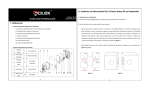
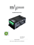
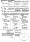
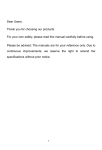
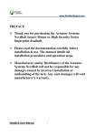
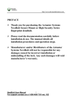
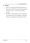
II. Check door dimensions and determine desired “door swing” 1. Installation Requirements The fingerprint deadbolt can be installed on doors of 1.5 – 2 inches (35-50) mm in thickness. 2. Check the direction in which the door is being opened (i.e. right or left-handed swing) and align the deadbolt’s I. Quick Reference latch-bolt, accordingly. A. Quick reference for Installation Guide II. Check door dimensions and determine desired “door swing” (1). The deadbolt’s body outside and inside must align properly. Assume you are standing outside the III. Install Deadbolt Body room/structure and facing a door. Basically there are four door opening-directions: Left inward, left IV. Install the Front panel Assembly outward, right inward and right outward. Left inward/outward means the door swings inward/outward V. Install the AA Batteries with hinges on the left; right inward/outward means the door swings inward/outward with hinges on the VI. Install the Rear panel Assembly right (see Figure 1 below): VII. Operating Instructions VIII. Routine Maintenance (2). Determine the deadbolt’s correct alignment/positioning based on the door’s opening direction (see Figure 2 below): B. List of Lock Accessories 1 2 Keyhole Cover Front panel Assembly 6 Screw (4 PCS) 7 4 PCS AA Batteries Silica gel 3 backing 8 plate 4 5 Lock body Back Lining Plate Rear panel assembly 9 Screw (2PCS) 10 Key (2PCS) Figure 2 Figure 1 -1- -2- (3). To set the deadbolt as "Left Open" or "Right Open" on the Rear panel Assembly, reference Figure 3: III. Install Deadbolt Body 1. Determine the desired installation height and position of the deadbolt in relation to the door; then adhere the hole-drilling-template to the door, accordingly (see Figure 4-1 below). 2. Insert the deadbolt body into the matching hole slot (see Figure 5 below): Note: There is an "UP" symbol on the deadbolt body. Before installing the deadbolt body, make sure its positioning is consistent with the direction of the symbol. Figure 3 As shown in Figure 3, there is a "Left open/Right Open" set switch on the rear panel assembly of the deadbolt. Note the user can turn the switch to the left side (L) to set the door's opening direction as "Left Open"; or turn the switch to the right side (R) to set the door's opening direction as "Right Open". Figure 4-1 Figure 4-2 Figure 5 Set the length of the deadbolt body based on the distance from the Door Edge to the center of the circle (the opening hole distance is about 2 ½ inches ( 65 mm), as shown in Figure 4-1). The opening distance matching the Note: default length of the deadbolt body is 2 ¼ inches (60 mm). If the distance of 2 ¾ inches (70 mm) is required, reset ① Before installing the deadbolt, you must first determine the door's opening direction as either “left the length of the deadbolt body by following these steps: open” or “right open”. (1) Figure 4-2: Hold part ① of the Deadbolt Body, rotate part ② by 45°, and pull back part ②. ② According to the door's opening direction, switch the "Left/Right Open" set switch to the corresponding (2). Rotate part ② by 45° in the other direction to make the hole on part 2 match with the hole of 2 ¾ inches position (For “Left Open”, position the switch to the left side; For “Right Open” position the switch to the (70 mm) on the lock body. Note: When you shorten the length of the Lock Body, perform the following steps: right side). (1). Hold part ①, rotate part ② by 45°, and push part ② ahead. (2). Rotate part ② by 45° in the other direction to make the card pillar of the lock body be embedded into the matching card hole of 2 ¼ inches (60 mm). -3- -4- 3. After the procedure is completed, secure the Deadbolt Body using a screwdriver, as shown in Figure 6. 2. Stretch the spring bolt back to the Deadbolt Body and pull the connecting wire out of the hole at the Insert the screwdriver into the cross-shaped hole of the Deadbolt bottom of the deadbolt Body. When you rotate the cylinder body. clockwise, it springs out automatically, as shown in Figure 7. When you rotate the cylinder counterclockwise, 3. Install the front panel assembly into the matching hole on the door. (There are three holes on the Deadbolt it springs back automatically, as shown in Figure 8. Body, as shown in the preceding figure. The cylinder on the fore plate composition must be pulled out from the cross-shaped hole of the Deadbolt Body and the locking bar must be vertical to the ground.), as shown in Figure 13. 4. Install the back lining plate to the mapping hole. Pull the connecting wire out of the oval-shaped hole of the back lining plate (As shown in Figure 14), attach the back lining plate and front panel assembly using a screwdriver, as shown in Figure 15. Figure 6 Figure 7 Figure 8 IV. Install the Front panel Assembly 1. Install the Silica gel backing plate on the Front panel Assembly as shown in Figure 12. Silica gel backing plate Figure 12 Figure 15 Figure 14 Figure 13 Front panel Assembly -5- -6- 3. Place the silica gel backing plate on the rear panel assembly, turn the lock button to make the hole slot V. Install the AA Batteries vertical to the ground, and insert locking bar into the hole slot (see Figure 19 below). In this case, when you 1. Obtain four AA batteries (preferably same brand). turn the lock button, the latch-bolt can spring out or back automatically. 2. Insert the batteries into the Rear panel Assembly properly. As shown in Figure 16-1 and 16-2: AA batteries Rear panel Assembly Figure 20 Figure 19 4. Place the rear panel assembly on the door to ensure that it can cover the whole back lining plate. Install Figure 16-2 Figure 16-1 screws and tighten them using a screwdriver as shown in Figure 20. VI. Install the Rear panel Assembly VII. Operating Instructions 1. Pull the connecting wire into the plug slot of the rear panel assembly as shown in Figure 17: 1. Panel Description ①Fingerprint Sensor ⑥Mounting Screw Holes ②Lock/Unlock button/ LED Status indicator ③Numerical keypad Wire Hole ④Key Hole/cover Figure 17 ⑦Lock lever Figure 18 ⑤Emergency 9V battery 2. Tuck the connecting wire as shown in Figure 18. connector -7- -8- 2. Precautions (1). After the deadbolt ① ② lock is installed, the deadbolt is in the “test state”, and therefore any fingerprints and PIN codes can open the deadbolt lock. Therefore, you must first change the Master Pass Code (MPC). The deadbolt can be used normally only after an “Administrator User” is enrolled. If the MPC is not changed, none of the functions in the deadbolt (except deadbolt initialization) available. If no “Administrator User” is registered, “Ordinary Users” cannot be enrolled, are either. Note: For instructions on how to change the Master Pass Code, Enroll Administrator User or Enroll Ordinary User, please see BL100 Fingerprint Deadbolt User Manual. (2). Do not remove batteries when matching, enrolling or deleting fingerprints because the sudden power-loss may result in data loss of fingerprint templates. Prior to removing batteries, make sure the deadbolt is not being operated. (3). It is recommended to replace the deadbolt batteries at least once every six months to avoid damaging the deadbolt’s electronics due to the battery corrosion. Do not use poor-quality batteries. 3. LED Backlight Indicators 5. Battery Low Voltage Protection When the AA batteries are running low, the deadbolt’s low-voltage alarm signals users to change the batteries as follows: The LED Backlight Indicators contain three colors: Red, Green and Blue. The general rule: 1. When the battery voltage reaches lower than 4.8V, the alarm buzzer will make a short sharp sound five times. Users can unlock the deadbolt normally but will not be able to enter the administrative user mode. Successful user operation: The buzzer sounds once and the LED indicator will turn green for 3 seconds. 2. When the battery voltage reaches lower than 4.5V, the alarm buzzer will make a short sharp sound five Failed user operation: The buzzer sounds short tone twice and the LED indicator turns red for 3 seconds. times, and then the deadbolt will power off Verify State: LED flashes Green. Management Mode: Blue LED will turn on and green LED will turn off. Warning Indication: The buzzer beeps five times intermittently. Note: When the low-voltage alarm occurs, please change the batteries immediately to help prevent data loss (It is suggested to change the batteries immediately when the battery voltage is lower than 4.8V). 4. Unlock with an Emergency Mechanical Key You can open the door using an emergency mechanical key in case the electronic component does not operate. ① Use your fingernails or a hard chip to remove the lock cover. ② Insert the key into the keyhole and rotate 90º to unlock. -9- -10- VIII. Routine Maintenance 1. The deadbolt’s surface should not be exposed to corrosive substances. Otherwise, the protective layer of the deadbolt’s surface may be damaged, and therefore the “glossiness” of the deadbolt surface may decrease. To keep the deadbolt surface glossy, use furniture polish (i.e. Pledge) wax to polish the deadbolt lock regularly. 2. Use a soft dry cloth to wipe built-up dirt on the fingerprint sensor 3. Change the batteries immediately when the after being used for a long time. low battery power alarm sounds. We recommend replacing the four old batteries with four new batteries of the same brand. Don’t mix and match new and used batteries. 4. Regularly check whether screws are loose. Tighten screws when necessary. -11-