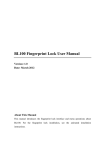
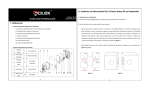
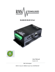
1
B. List of Lock Accessories BL100 Installation Guide Version: V1.0 Date: 2012.3.16 1 2 Ⅰ . Reference Tools for Installing the Door Lock 3 4 1 Hammer 2 Screwdriver 3 Chisel for wood working 4 Angle square Keyhole Cover Front panel Assembly Silica gel backing plate Lock body 6 Screw (4 PCS) 7 8 4 PCS AA Batteries Rear panel assembly 9 Screw (2PCS) 10 Key (2PCS) 5 Percussion drill 5 Back Lining Plate Ⅲ . Confirm the door information before installation 6 Hole saw 7 Polisher 8 Rivet gun 9 Carpenter's pencil 10 Pliers 1. Installation Requirements Ⅱ . Quick Reference This fingerprint lock is not configured with a handle, and the user can install it on the door as desired. The A. Quick reference for Installation Guide fingerprint lock is applicable to doors of 3550 mm in thickness. Confirm the door information before installation, please see Ⅲ. Confirm the door information before 2. Make sure of the door opening directions and lock body directions installation; (1). Make sure of the door opening directions. The lock body's outside and inside can't be set contrary. Assume Ø Install Lock Body, please see Ⅳ. Install Lock Body; you are standing outside and facing a door and then there are four door opening directions: Left inward, left Ø Confirm the length of Locking Bar, please see Ⅴ. Confirm the length of Locking Bar; outward, right inward and right outward. Left inward/outward means the door swings inward/outward with Ø Install the Front panel Assembly, please see Ⅵ. Install the Front panel Assembly; hinges on the left; right inward/outward means the door swings inward/outward with hinges on the right, as Ø Install Batteries, please see Ⅶ. Install the Batteries; shown in the following Figure 1: Ø Install the Rear panel Assembly, please see Ⅷ. Install the Rear panel Assembly; (2). Make sure of the lock body directions. According to the door opening directions to make sure of the lock Ø Use Instruction, please see Ⅸ. Use Instructions; body directions, shown as the following Figure 2: Ø The Basic Operation, please seeⅩ. The Basic Operation; Ø Ø Routine Maintenance, please see Ⅺ. Routine Maintenance. 1 2 Ⅳ. Install Lock Body 1. Determine the installation height and installation location; stick the holedrilling template to an appropriate location according to the dooropening mode, as shown in Figure 41. 2. Insert the Lock Body into the matching Hole Slot. as shown in Figure 5: ? Note: There has a "•UP" flag on the Lock Body. Before installing the Lock Body, confirm how to install it Figure 1 Figure 2 based on the tip flag. (3). To set the lock as "Left Open" or "Right Open" on the Rear panel Assembly, shown as Figure 3: Figure 41 Figure 42 Figure 5 Set the length of the Lock Body based on the distance from the Door Edge to the center of the circle (that is, the opening hole distance is about 60 mm or 70 mm, as shown in Figure 41). The opening distance matching the default length of the lock body is 60 mm. If the distance of 70 mm is required, Figure 3 reset the length of the lock body in the following steps: As shown in Figure 3, there has a "Left open/Right Open" set Switch on the Rear panel Assembly of the fingerprint (1). Hold the part ① of the Lock Body, rotate the part ② by 45°, and pull back part ②. As shown in Figure 42. lock. The user can turn the switch to the left side (L), namely set the door's opening directions as "Left Open"; if (2). Rotate part ② by 45° in the other direction to make the card pillar of the Lock Body to be embedded into the turn the switch to the right side (R), then set the door's opening directions as "Right Open". matching card hole of 70 mm. That is, set the length of the Lock Body to 70 mm. Note: ① Before install the fingerprint lock, you must make sure of the door's opening direction as Left Open or Right Open at first; ② According to the door's opening direction, switch the "Left/Right Open" set switch to the J corresponding position (Left Open, then switch to the left side; Right Open, then switch to the right side); ③ (1). Hold the part ①, rotate the part ② by 45°, and push part ② ahead. (2). Rotate part ② by 45° in the other According to the door's opening direction to drill a hole and trough in the door, and then install the Lock Body. direction to make the card pillar of the Lock Body to be embedded into the matching card hole of 60 mm. 4 3 Note: When you shorten the length of the Lock Body, perform the following steps: 3. After the procedure is completed, fix the Lock Body using a screwdriver, as shown in Figure 6. Insert the screwdriver into the crossshaped hole of the Lock Body. When you rotate the cylinder clockwise, it springs out Ⅵ. Install the Front panel Assembly automatically, as shown in Figure 7. When you rotate the cylinder counterclockwise, it springs back automatically, 1. Install a Silica gel backing plate on the f Front panel Assembly (moisture proof / waterproof). As shown in as shown in Figure 8. Figure 12. Silica gel backing plate Figure 6 Figure 7 Figure 8 Ⅴ. Confirm the length of Locking Bar Figure 12 Figure 13 Front panel Assembly 1. Install the Front panel Assembly of the lock onto the door (Please see Ⅵ . Install the Front panel Assembly ). As 2. Stretch the Spring Bolt back to the Lock Body and pull the Connecting Wire out of the hole at the bottom of the shown in Figure 9: Lock Body. 3. Install the Front panel Assembly into the matching Hole Slot on the door. (There are three holes on the Lock Body, as shown in the preceding figure. The cylinder on the fore plate composition must be pulled out from the crossshaped hole of the Lock Body and the Locking Bar must be vertical to the ground.), as shown in Figure 13. Figure 9 Figure 10 Figure 11 4. Install the Back Lining Plate to the mapping Hole Slot. Pull the Connecting Wire out of the Ovalshaped Hole of the Back Lining Plate (As shown in Figure 14) and fix the Back Lining Plate and Front panel Assembly using a screwdriver, as shown in Figure 15. 2. Check whether the Locking Bar is too long. If yes, take the Front panel Assembly off and cut away the excess part of the Locking Bar (see Method for Cutting Locking Bar). As shown in Figure 10. Method for cutting Locking Bar: Suppose that the part of the Locking Bar that stretches out of the Hole Slot on the door is CD, as shown in Figure 11. Cut away the Locking Bar from A to ensure that the Locking Bar does not stretch out of the Hole Slot. 5 Figure 14 Figure 15 6 Ⅶ. Install the Batteries 3. Cover the Silica gel Backing Plate onto the Rear panel Assembly, turn the Lock Button to make the Hole Slot 1. Prepare four AA batteries. You are advised to use new batteries with the same brand. turn the Lock Button, the bolt can sprung out or back automatically. vertical to the ground, and insert Locking Bar into the Hole Slot, as shown in Figure 19. In this case, when you 2. Put batteries into the Rear panel Assembly properly. As shown in Figure 161 and 162: AA batteries Rear panel Assembly Figure 161 Figure 20 Figure 19 4. Push the Rear panel Assembly ahead to ensure that it can cover the whole Back Lining Plate. Install screws and Figure 162 fix them using a screwdriver. As shown in Figure 20. Ⅷ. Install the Rear panel Assembly Ⅸ . Use Instructions 1. Pull the Connecting Wire into the Wire Hole of the Rear panel Assembly. As shown in Figure 17: 1. Panel Description ①Fingerprint Collector ⑥Screw Hole ②Start key/ LED Status indicator ③Number keys Wire Hole ④Key Hole Figure 17 2. Tuck up the Connecting Wire for further Rear panel Assembly installation. As shown in Figure 18. 7 ⑦Lock Button Figure 18 ⑤Emergency Power Interface 8 ① 2. Precautions ② (1). After the fingerprint lock is installed, the lock is in the test state, and therefore any fingerprints and passwords can open the lock. You must modify the Master Pass Code (MPC). The lock can be used normally only after the User ID of an administrator is entered. If the MPC is not modified, the other functions of the system except for the initialization system are not available in the management mode. If no administrator is registered, ordinary users cannot also be registered. J Note: The method and step of change Master Pass Code, Enroll Administrator and Enroll Ordinary user, please see BL100 Fingerprint Lock User Manual. (2). Do not remove batteries when matching, enrolling or deleting fingerprints because the sudden powerdown may result in data loss of fingerprint locks. Prior to removing batteries, make sure the fingerprint lock is not in working state. (3). It is recommended to replace the fingerprint lock batteries at least once every six months to avoid damaging the 5. Battery Low Voltage Protection circuit due to the battery leakage. Do not use batteries with poor quality. When the battery is low, there are alarm signals to warn users to change the battery as follows: 3. LED Backlight Indicators (1). When the battery voltage is lower than 4.8V, the buzzer will make short sharp sounds for five times when The LED Backlight Indicators content three colors: Red, Green and Blue. starting the machine. Users can unlock it normally but fail to enter the administrative mode. Ø (2). When the battery voltage is lower than 4.5V, the buzzer will make short sharp sounds for five times, and then The general rule: Successful = 1 Long Beep / LED Flashes Green. the machine will be switched off automatically. Failed = 2 Short Beeps / LED Flashes Red. Ø Verify State: Green LED flash by second. J Ø Management Mode: Blue LED flash by second the fingerprint lock. Avoid losing data caused by instable power supply (It is suggested to change the battery Note: When the lowvoltage alarm occurs, please change the battery in time to avoid the impact on the work of 4. Unlock with an Emergency Mechanical Key immediately when the battery voltage is lower than 4.8V). You can open the door using an emergency mechanical key in case the electronic component does not operate. ① Use your fingernails or a hard chip to take down the lock cover. Ⅹ. The Basic Operation ② Insert the emergency key into the keyhole and rotate 90º to unlock. Ⅰ. Change Master Pass Code (MPC) 1. Press key to start lock, and then enter the Verify State. The LED flashes green light, and the Numpad area's blue light will be on. 2. Press and hold the key until you hear 1 long beep and the Green LED put out, and then the Keypad area Flashes Blue light. Press number key of the lock to input the default MPC "98989", and then press enter the Management Mode. The green LED put out and the Keypad area continue flash blue light. 9 10 key to 3. Press "5" key on the lock and enter the new 5 digits MPC, then press the MPC once again then press the key to confirm. Enter the new key to confirm. Once you hear 1 long beep and the key flashes green, Ⅲ. Enroll an Ordinary User Ø Enroll a Fingerprint Ordinary User namely you have successfully changed the MPC code. 1. Press Ⅱ . Enroll an Administrator 2. There have two methods to enter the Management Mode: ① Press and hold the 1. Press beep, enter the 5 digits MPC, and then press key to start lock, and then enter the Verify State. 2. Press and hold the key until you hear 1 long beep, enter the 5 digits MPC, and then press key to key to start the lock and enter the Verify State. key to enter the Management Mode. ② Verify the registered administrator's password and fingerprint to enter the Management Mode. enter the Management Mode. 3. Press "1" to enter the Enroll Ordinary User's Fingerprint Mode. 3. Press "9" on the lock to enter the Enroll Administrator Mode. 4. Input 3 digits User ID, then press Ø J Enroll a Fingerprint Administrator User key until you hear 1 long key to confirm. Note: The ordinary users' ID must between "001" and "994". J Note: 13 steps are same as above. Here is no longer to restatement. 5. Press finger in the scanner area properly, and repeat it for three times, until you hear one long beep and LED 4. After enter the Enroll Administrator Mode, press number keys of the lock to enter 3 digits user ID, and then press flashes Green, namely enrollment successful. Ø key to confirm. Enroll a Password Ordinary User J 1. Press 5. Press finger in the scanner area properly, and repeat it for three times, until you hear one long beep and LED 2. Press "2" on the lock to enter the Enroll Ordinary User's Password Mode. flashes Green. 3. Input 3 digits User ID, and press Ø J Note: The administrator User's ID must between "995" and "999". how to enter the management mode in the Enroll a Fingerprint Ordinary Users. Enroll a Password Administrator User key to confirm. Note: The ordinary users' ID must between "001" and "994". J Note: 13 steps are same as above. Here is no longer to restatement. 4. After enter the Enroll Administrator Mode, enter 3 digits user ID, press 5. Press 4 digits user password and press and press key to start the lock and enter the Verify State. Enter the Management Mode; see the methods on 4. Input 4 digits user password, press key to confirm. key to confirm, and then enter the 4 digits user password once again key to confirm, until you hear one long beep and LED Flashes Green (If it fails to register it will key to confirm. Enter the 4 digit user password once again and press key to confirm until you hear one long beep and LED flashes Green. The Keypad area lights blue LED and the key lights green LED, namely register successful. Ⅳ. User Verification give 2 short beeps and LED will flash red). Ø J 1. Press If your input the wrong at the third time, then it will prompt fail registration. In this case you will need to follow step (1) If verify successful, the buzzer will give a long beep and unlock automatic, the green LED and the Fingerprint 1 to operate again. ② If successful, it will automatically exit the Enroll Administrator Mode. ③ Press and hold "0" Collector will put out, the Green LED at key, can exit anytime. ④ If you want to enroll more administrator user, and then repeat the step 15. key to lock. Note: ① If Pass code does not match or input the wrong digit password, then you have two times to try again. 11 The Fingerprint Verification key to start the lock and enter the Verify State. The Fingerprint Collector is in active state. 2. Press finger in the fingerprint scanner area properly, until you hear one long beep, namely collect successful. key will light for 3 seconds, at this moment your can press 12 (2) If verification failed. The buzzer will give two short beeps, the red LED at key will light for 3s, then the 3. Input "000" and press green LED will flash, the user can use fingerprint to verify again until verify successful. will give a long beep, the Ø ? The Password Verification 1. Press 2. Press number key of lock to input the correct 4 digits password, and press key flash green light, namely successful delete all users. operation. key to confirm. (1) If the password is correct, then verify successful, the buzzer will give a long beep and unlock automatic, the can press the key to confirm. The buzzer Notice: The operation can only delete ordinary users. If you want to delete administrator, you should do reset key to start the lock and enter the Verify State. green LED at Fingerprint Collector will put out, the Green LED at key to confirm, then input "000" again and press key will light for 3s, at this moment you Ⅺ. Routine Maintenance 1. The lock surface is forbidden to contact corrosive substances. Otherwise, the protective layer of the lock surface key to lock. (2) If the password is wrong, then the verification failed. The buzzer will give two short beeps, the RED LED at key will light for 3s, then the green LED will flash, the user can input password to verify again until verify may be damaged, and therefore the glossiness of the lock surface may be decreased. To keep the lock surface glossy, use the furniture polish wax to polish the lock surface regularly. successful. 2. Use the cloth to clean dirt after the fingerprint collector is used for long time. J 3. Change batteries in time when the alarm on the low power rings. You must replace the four old batteries with four Note: After successful verification, the lock is in unlocking state. If you want to lock, press key to start new batteries of the same brand (the alkaline battery of 1.5 V) once. 4. Regularly check whether screws are loose. the lock, and then press this key again to lock and power off. Ⅴ. Delete User Ø Delete a user 1. Press key to start the lock and enter the Verify State. See the methods on how to enter the management mode in the Enroll a Fingerprint Ordinary Users. 2. Press "3" on the lock to enter the Delete User Mode. 3. Press number key of the lock to input the User's ID which one you want to delete, and then press confirm. Input the user ID again, and press key to confirm, the buzzer will give a long beep, the key to key lights green light, namely successful delete the user. 4. After deleting the user, you can restart the fingerprint lock and verify the deleted user's fingerprints or password again to check whether the user is deleted for sure. ? Notice: The administrator can't delete itself and the last administrator. Ø Delete All Ordinary Users 1. Press key to start the lock and enter the Verify State. See the methods on how to enter the management mode in the Enroll a Fingerprint Ordinary Users. 2. Press "6" on the lock to enter the Delete All Ordinary User Mode. 13 14