1
Video Eyetracker Toolbox
User Manual
version 3.11 January 2006
Cambridge Research Systems Ltd
80 Riverside Estate
Sir Thomas Longley Road
Rochester
Kent ME2 4BH
England
www.crsltd.com
1
Video Eyetracker Toolbox
Version
Date
Changed by:
Description of Changes
3.11
18 Jan 06
M. Hodgetts
S. Elliott
New sections for High-Speed
Video Eyetracker Toolbox
Revised videoEyetrace
description
Added MATLAB worked
examples
Appropriate commands from
the CRS Toolbox for
MATLAB described in the
Appendix
Description of COM Server
interface removed
2
Video Eyetracker Toolbox
Introduction
9
Overview of Video Eyetracker Toolbox Family
10
CRS Video Eyetracker Toolbox
12
50 Hz Video Eyetracker Toolbox
12
High-Speed Video Eyetracker Toolbox
12
Images Acquired with 50 Hz and High-Speed Systems13
Calibration
15
Monitor Configuration and Calibration
Dual VGA
TM
Dual VGA with GazeTracker
CRS Visual Stimulus Generator
Non-Computer-based Custom Display Device
Positioning and Focusing your Subject (Imaging)
Subject Calibration
Pupil Scale Calibration
Subject Gaze Calibration
Hardware states after Subject Calibration
CRS Visual Stimulus Generator
Dual VGA
Custom Device
3
16
16
18
19
20
21
24
25
27
33
33
34
34
Video Eyetracker Toolbox
videoEyetrace
35
Overview
The videoEyetrace Window
Initialising the Video Eyetracker Toolbox Camera
Title bar
Menu bar
Toolbar
Data windows
Status bar
Changing Stimuli and Settings
Changing View Options
Graph Tab
Configuration Tab
Mimic Tab
EIB Tab (High-Speed System only)
Eye Tracking
Saving and Loading
Data Files (*.ved)
Custom Results Data File (*.ved)
MATLAB Data File (*.mat)
Mimic Image (*.bmp)
Communicating with the Toolbox
Synchronisation – 50 Hz Systems
Synchronisation – High-Speed Systems
Eyetracker Interface Box -- Inputs
CRS ViSaGe
CRS VSG 2/5
Eyetracker Interface Box -- Outputs
Video Eyetracker Toolbox and MATLAB
Worked MATLAB Eye Tracking Examples
Example 1: Bitmap Stimulus with Dual VGA
Example 2: Triggered Saccade Stimulus for ViSaGe
Appendices
Appendix A
36
36
37
37
38
38
39
40
40
41
42
43
43
44
45
48
48
49
49
49
51
52
54
54
55
56
57
57
58
58
68
79
MATLAB Commands
Functions
Events
vetAddRegion
vetCalibrate
vetCalibrateAdvanced
81
82
83
84
85
86
4
Video Eyetracker Toolbox
vetClearAllRegions
vetClearDataBuffer
vetClearMimicScreenBitmap
vetCreateCameraScreen
vetCreateMimicScreen
vetDeleteRegion
vetDestroyCameraScreen
vetDestroyMimicScreen
vetGetActiveRegion
vetGetBufferedEyePositions
vetGetCalibrated
vetGetEIB_LEDsENABLED
vetGetEIB_XYOutputType
vetGetFixationLocation
vetGetLatestEyePosition
vetGetMimicScreenBitmap
vetGetPupilCalibrated
vetGetRegionCount
vetGetResultsCount
vetGetTracking
vetGetToolboxVersion
vetGetVideoSourceFile
vetGetVideoSourceType
vetIsEyeDataAvailable
vetLoadBmpFileToMimicScreen
vetLoadCalibrationFile
vetLoadBitmapToMimicScreen
vetSaveCalibrationFile
vetSaveMimicScreenBitmap
vetSaveResults
vetSelectVideoSource
vetSetCameraScreenDimensions
vetSetDeviceParameters
vetSetEIB_LEDsENABLED
vetSetEIB_XYOutputType
vetSetFixationPeriod
vetSetFixationRange
vetSetMimicBackgroundColor
vetSetMimicFixationColor
vetSetMimicPersistence
vetSetMimicPersistenceStyle
vetSetMimicPersistenceType
vetSetMimicScreenDimensions
vetSetMimicTraceColor
5
87
88
88
88
89
89
90
90
90
91
93
93
93
94
95
96
96
97
97
98
98
98
99
100
100
101
102
102
103
103
104
106
106
107
108
108
109
110
110
111
111
112
113
113
Video Eyetracker Toolbox
vetSetStimulusDevice
vetSetUIMonitor
vetSetViewingDistanceMM
vetStartRecordingToFile
vetStartTracking
vetStopRecording
vetStopTracking
vetSetCallbackClearDisplay
vetSetCallbackCollectResults
vetSetCallbackDrawTarget
vetSetCallbackFixate
vetSetCallbackInitialiseDisplay
vetSetCallbackRegionChanged
Appendix B Imaging Geometry
Illumination Geometry
Illumination Geometry
Calibration Geometry
114
115
115
116
116
117
117
117
118
119
119
120
120
122
122
123
124
Appendix C Template for Fixed Mount
EyeLock Headrest
127
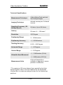
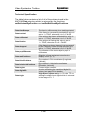
Appendix D Technical Specification
Technical Specifications
129
130
Appendix E Hot Mirror Spectral
Transmission
131
Appendix F Fick and Helmholtz Coordinates
133
Technical Description
Appendix G
134
Data Returned by the Toolbox
135
Technical Specification
Technical Specification
135
136
Appendix H Troubleshooting
System slow to calibrate
137
139
6
Video Eyetracker Toolbox
System fails to calibrate
System fails to track the eye
System fails to track the Pupil
System fails to track the Purkinje Glints
Eye tracking appears inaccurate
Eye tracking appears noisy, erratic or intermittent
Notes
139
139
140
142
143
143
147
7
Video Eyetracker Toolbox
In this section…
Overview of the Video Eyetracker Toolbox Family
10
CRS Eyetracker Toolbox
50 Hz Video Eyetracker Toolbox
250 Hz High-Speed Video Eyetracker Toolbox
Images Acquired with 50 Hz and 250 Hz Systems
12
12
12
13
9
Video Eyetracker Toolbox
Overview of Video Eyetracker Toolbox Family
This manual is intended to cover the hardware and software use
of the Cambridge Research Systems Video Eyetracker Toolbox
family of eye trackers. It is intended to be read only when all the
steps in the corresponding Installation Manual have been
successfully completed.
The Video Eyetracker Toolbox family of 50 Hz and 250 Hz video
eye trackers share most of their functionality in common. As a
result, this document will treat common functionality without
reference to particular models and add sections specific to
particular versions only where necessary.
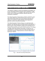
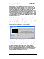
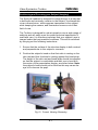
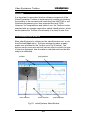
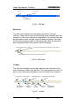
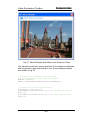
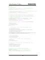
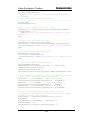
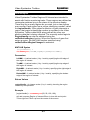
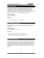
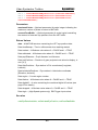
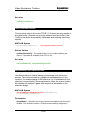
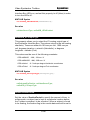
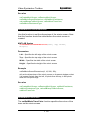
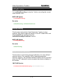
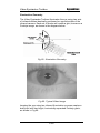
The Video Eyetracker Toolbox allows you to add robust and
accurate eye tracking to new or existing experimental systems. In
addition, your Video Eyetracker Toolbox comes complete with a
demonstration program called videoEyetrace which allows you to
calibrate a test subject and present simple image files. If you have
a suitable CRS Visual Stimulus Generator you can also use
videoEyetrace to present smooth pursuit and saccade stimuli for
oculomotor research. These topics are covered in detail in the
following 2 chapters.
Fig 1. Smooth Pursuit Eye Movements
10
Video Eyetracker Toolbox
Once you become familiar with the operation of your Video
Eyetracker Toolbox, you can exploit the Toolbox’s open interface
design either to:
•
Integrate eye tracking functionality with your existing
laboratory software or
•
Write new eye tracking applications using a familiar
programming environment.
Your Video Eyetracker Toolbox is designed to allow all aspects of
its functionality to be accessed and controlled from MATLAB or
any Windows programming tool that support Microsoft COM. A
complete description of the MATLAB interface, including worked
examples, is covered in the final chapter of this manual. A
separate document describing the COM interface and examples
in Delphi, C++ Builder and Visual Basic are available to download
from the Cambridge Research Systems Support Portal
(www.crsltd.com/support/login).
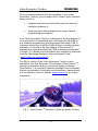
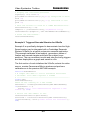
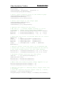
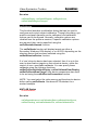
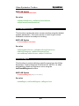
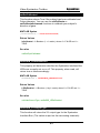
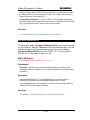
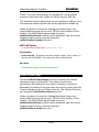
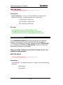
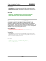
The 50 Hz version of the Video Eyetracker Toolbox is also
TM
compatible with Eye Response Technologies’s GazeTracker
stimulus presentation and eye movement analysis software.
GazeTracker™ is a powerful software package that consolidates
stimulus presentation, information synchronisation, data analysis
and visualisation. See our website (www.crsltd.com) for further
information.
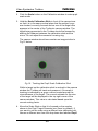
Fig 2. GazeTracker
TM
Analysis of Dynamic Scene Content
11
Video Eyetracker Toolbox
CRS Video Eyetracker Toolbox
The Video Eyetracker Toolbox family of video eye trackers are
designed to work with a standard PC running Windows XP
without any custom processing hardware. Apart from the obvious
difference in the range of supported video frame rates, from a
user’s perspective, all systems share most of their functionality in
common. This document will therefore treat common functionality
by default and only refer to specific systems where necessary.
50 Hz Video Eyetracker Toolbox
The 50 Hz Video Eyetracker Toolbox is a monocular eye tracker
primarily intended for gaze tracking applications where the
objective of the research is to determine where a test subject is
looking and for how long. The videoEyetrace picture in Fig 1 is an
example of where the 50 Hz system has been used to track a
horizontal smooth pursuit target while monitoring pupil diameter.
The 50 Hz systems are supplied with one of two different camera
configurations called: Standard Camera or Standard Camera-I.
Standard Camera uses a progressive scan mode to acquire the
video frames whereas Standard Camera-I uses an interlaced
mode. Both will give equivalent performance but it will be
necessary to select the appropriate type to match the supplied
camera configuration before enabling the eye tracker. Standard
Cameras are supplied unlabelled whereas Standard Camera-I
versions are supplied with a label on the camera assembly.
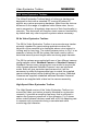
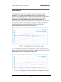
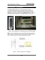
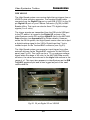
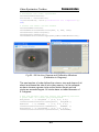
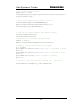
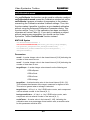
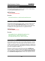
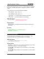
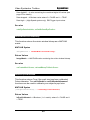
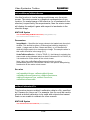
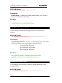
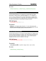
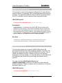
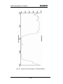
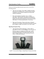
High-Speed Video Eyetracker Toolbox
The High-Speed version of the Video Eyetracker Toolbox is a
monocular video eye tracker primarily intended for oculomotor
research. It provides a sampling frequency that is sufficient to
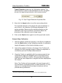
capture the frequency spectrum of eye dynamics. Fig 3 shows
where videoEyetrace has been used with a 250 Hz sampling rate
to measure eye movements during a saccade task while
monitoring pupil diameter.
12
Video Eyetracker Toolbox
Fig 3. High-Speed Eyetracker with Saccade Stimulus
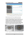
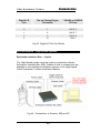
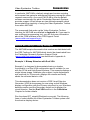
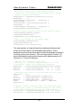
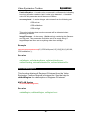
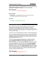
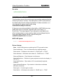
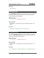
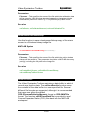
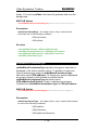
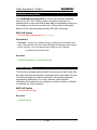
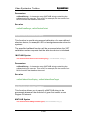
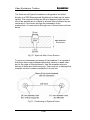
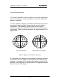
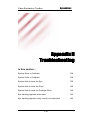
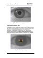
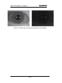
Images Acquired with 50 Hz and High-Speed Systems
The major difference between the 50 Hz and High-Speed
versions of the Video Eyetracker Toolbox lies in the camera and
illumination geometries required to operate at higher frame rates.
The 50 Hz system uses a standard CCD sensor whereas the
High-Speed version requires a CMOS sensor to operate at
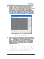
frequencies up to 250 Hz. In addition, the dual Purkinje glints
generated by the infrared illumination sources will appear slightly
larger in the images obtained by the High-Speed version as more
illumination is required to obtain clear high contrast images.
Fig 4. Comparison of 50 Hz (left) and 250 Hz (right) Images
13
Video Eyetracker Toolbox
In this section…
Monitor Configuration and Calibration
Dual VGA
TM
Dual VGA with GazeTracker
CRS Visual Stimulus Generator
Non Computer-based Custom Display
16
16
18
19
20
Positioning and Focusing your Subject
21
Subject Calibration
Pupil Scale Calibration
Subject Gaze Calibration
24
25
27
Hardware states after Subject Calibration
CRS Visual Stimulus Generator
Dual VGA
Custom Device
33
33
34
34
15
Video Eyetracker Toolbox
Monitor Configuration and Calibration
The Video Eyetracker Toolbox is primarily designed to work in a
dual computer screen configuration with separate displays for the
Windows desktop and visual stimulus. It is also possible to use
the system with a non computer-based display such as a TV,
blackboard or LED array. However, in this scenario, you must
manually configure and calibrate your display source and subject.
To provide a second stimulus display, you can either use a single
PC graphics card with dual outputs, two separate PC graphics
cards, or a CRS Visual Stimulus Generator e.g. the ViSaGe.
Whichever solution you choose to use it is extremely important to
correctly calibrate the stimulus display in terms of viewing
distance, screen resolution and scale. The following sections
describe the calibration process for each presentation device.
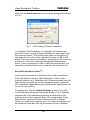
Dual VGA
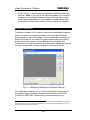
If you are using the Toolbox in a Windows dual display
configuration, you must calibrate the size of the stimulus display.
The Toolbox assumes a minimum of two monitors; the Primary
monitor is used to display Windows desktop and the Secondary
monitor to display the visual stimulus. It is the size and resolution
of this Secondary stimulus monitor that needs to be calibrated.
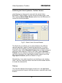
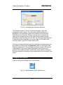
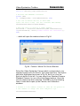
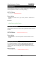
Fig 5. Display Properties
16
Video Eyetracker Toolbox
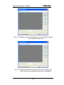
Before carrying out the calibration procedure ensure that the
Windows desktop has been extended to both monitors and that
the screen resolution and frame rates for the Primary (Windows
desktop) and Secondary (stimulus monitor) agree with the
minimum or recommended settings for both monitors as given in
the Installation Manual. (If you intend to use videoEyetrace, your
Primary and Secondary monitors must have a resolution of 1024
x 768 pixels.) These settings can be configured by a right mouse
click on the desktop and choosing the Properties option to open
the window shown in Fig 5.
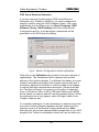
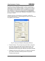
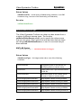
Once the Primary and Secondary screens have been suitably
configured, start the Toolbox’s VGA Calibration application
located in the Video Eyetracker Toolbox directory or from the
desktop via Start | Programs | Video Eyetracker Toolbox | VGA
Calibration. The VGA Calibration application will create a white
square on a black background on the Secondary monitor and
open the following window on the Primary monitor
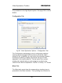
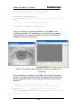
Fig 6. VGA Pixel Size Calibration
To calibrate the Secondary monitor you must measure the width
and height of the square using a ruler and, if necessary, adjust
the horizontal or vertical scales on the display monitor itself to
ensure that both measurements are equal. When the white
stimulus is truly square, enter its height / width in the ‘Size of
Square’ box and click OK. Note: this VGA Calibration procedure
will need to be repeated if the screen resolution of the second
monitor is subsequently changed in any way.
17
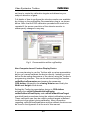
Video Eyetracker Toolbox
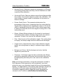
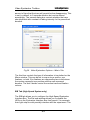
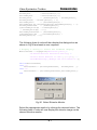
Now click the Advanced button to reveal the dialogue box shown
in Fig 7:
Fig 7. VGA Viewing Distance Calibration
To complete VGA Calibration it is necessary to measure and
enter the correct Viewing Distance between the test subject and
the stimulus monitor. This window also gives you the option of
changing the size of the white calibration square to 200 or 400
pixels. This is sometimes preferable if working with high resolution
monitors or if you are concerned with parallax measurement
errors. If this is changed to a 200 or 400 pixel white square, it is
important to measure and enter its new size as shown in Fig 6.
TM
Dual VGA with GazeTracker
GazeTracker operates in a different mode to the conventional
Dual VGA setup in that the Video Eyetracker Toolbox User
Interface controls (e.g. Calibration and Camera windows) and the
GazeTracker program run on the Secondary monitor, while the
VET calibration targets and stimuli presented by GazeTracker run
on the Primary monitor.
To achieve this, click the Switch Displays button on the VGA
Pixel Calibration Advanced Settings as shown in Fig 7 and then
complete the VGA calibration procedure as described in the
previous section for a standard Dual VGA configuration. Since
GazeTracker uses the Primary Windows monitor to display
stimuli, you may find it easier to use if you drag the desktop icons
and Windows Task Bar onto the Secondary monitor’s desktop.
18
Video Eyetracker Toolbox
CRS Visual Stimulus Generator
If you are using the Toolbox with a CRS Visual Stimulus
Generator (e.g. ViSaGe or VSG2/5), you must configure the
stimulus monitor using the VSG Software Library. First, open
vsgDesktop from the Start menu via Start | Programs | VSG
Software Library | VSG Desktop and click on the Monitor
Configuration plug-in. A red and green chessboard will be
presented on the VSG stimulus display.
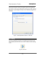
Fig 8. Monitor Configuration within vsgDesktop
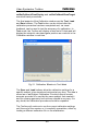
Now click on the Calibration tab (located in the main window of
vsgDesktop). The chessboard will be replaced with a white
square on the stimulus display. To calibrate this display you must
measure the width and height of the square using a ruler and, if
necessary, adjust the horizontal or vertical scales on the display
to ensure that both measurements are equal. (Please note that
the “The Size of Square” box gives you the option of changing
from a 100 pixel to either a 200 or 400 pixel white square which
will be easier to measure and will reducing parallax errors.) When
the white stimulus is truly square, enter its height / width in the
‘Height of Square’ box.
To complete calibration it is also necessary to measure and enter
the correct Viewing Distance between the test subject and the
stimulus monitor in the Default Viewing Distance box. Note:
although you can set the viewing distance parameter in your VSG
program, the Toolbox’s calibration routines will use the value you
19
Video Eyetracker Toolbox
set here to create the calibration targets and determine your
subject’s direction of gaze.
Full details of how to configure the stimulus monitor are available
by clicking on the vsgDesktop Documentation plug-in, as shown
below. Note: that the VSG calibration procedure will need to be
repeated if the screen resolution of the stimulus monitor is
subsequently changed in any way.
Fig 9. Documentation within vsgDesktop
Non-Computer-based Custom Display Device
If you are planning to use the Toolbox with a custom presentation
device you cannot calibrate the device directly. Instead you must
define the bounding dimensions of the device using the Toolbox’s
programming interface. This can be achieved using the function
vetSetDeviceParameters and passing the parameter
CRS.deUser followed by the viewing distance and finally the
Width and Height of the device.
Setting the Toolbox’s presentation device to CRS.deUser
activates the vetSetCallbackInitialiseDisplay,
vetSetCallbackClearDisplay and vetSetCallbackDrawTarget
event/call-back procedures during the subject calibration process.
These call-backs can then be used to present targets at defined
locations to the subject during calibration. More information
regarding vetSetDeviceParameters and the callback functions can
be found in the Appendix A at the end of this manual.
20
Video Eyetracker Toolbox
Positioning and Focusing your Subject (Imaging)
The EyeLock headrest is designed to image the eye in a way that
is both safe and minimally invasive to the subject. It achieves this
via an infrared mirror, which appears transparent to the subject
while keeping the camera, and illumination sources out of their
field of view.
The Toolbox is designed for robust operation over a wide range of
subjects and will easily meet its quoted technical specification if
used with care. It is therefore important that your subject’s eye is
imaged under the best possible conditions. This will be achieved
by carrying out the following instructions:
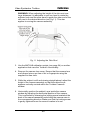
1. Ensure that the surface of the stimulus display is both centred
and perpendicular to this subject’s view axis.
2. Position the subject’s head so that their chin is resting on the
chin-rest and their forehead is resting against the head-strap.
The height of the chin-rest and head-strap should be adjusted
so that the subject is comfortable and their eye is level with
the centre of the presentation display, as shown below. Note:
the subject’s head should not be tilted as this may cause the
eye lid to obscure the pupil.
Fig 10. Correct Viewing Geometry
21
Video Eyetracker Toolbox
WARNING: When adjusting the height of the chin-rest over
large distances it is advisable to use one hand to rotate the
adjuster knob and the other hand to guide the other end of the
chin-rest in the desired direction (see Fig 11). This also
applies to moving the camera assembly.
Fig 11. Adjusting the Chin-Rest
3. Use the MATLAB calibration scripts (see page 24) or another
application that uses the Toolbox’s functionality.
4. Remove the camera lens cover. Ensure that the camera lens
and infrared mirror are free of dirt or fingerprints using the
supplied lint-free cloth.
5. While the subject is still and viewing straight ahead, adjust the
height of the camera assembly so that the subject’s eye
appears vertically centred within the Toolbox’s camera
window.
6. Horizontally position the subject’s eye inside the camera
window by adjusting the horizontal position of the camera.
This is achieved by releasing the locking screw located at the
back of the camera assembly and sliding the camera case in
the corresponding direction. Make sure that the locking screw
is gently tightened once the correct location is found.
22
Video Eyetracker Toolbox
WARNING (High-Speed System Only): The High-Speed
camera can get very warm when used for extended periods.
The camera case acts as a heat sink for the electronics inside
and therefore runs at an elevated temperature. This is normal
but your users should be aware of this.
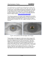
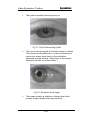
7. While the subject is still looking straight ahead, rotate the
focussing ring until the subject’s pupil (not their eyelashes or
eyebrow) appears as sharp as possible in the video image.
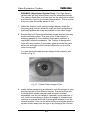
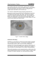
8. Ensure that both Purkinje reflections remain distinct from any
bright secondary glints. This may occur if the subject is
wearing glasses or if the ambient illumination contains a
significant infrared component. The Toolbox is designed to
cope with any number of secondary glints provided they are
either not as bright as the Purkinje reflections or do not lie
close to the pupil.
You should now be able see an image of the subject’s eye
similar to Fig 12.
Fig 12. Typical Video Image of Eye
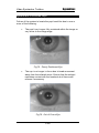
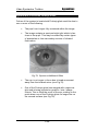
9. Lastly, before performing a calibration, ask the subject to view
the four corners of the stimulus screen. Ensure that the two
Purkinje glints remain compact and maintain constant
separation over the full range of intended eye movements. If
not, it will be necessary to reduce the range of intended eye
rotations to ensure that both Purkinje glints always lie on the
corneal surface. This can be achieved by moving the stimulus
screen further away from the eye or by changing the ‘Screen
23
Video Eyetracker Toolbox
Scale Factor’ in the Advanced Calibration Settings (see next
section). Note: if you move the stimulus display, you must remeasure the Viewing Distance and set the new value using
the scheme appropriate to your graphics configuration (see
the Monitor Configuration section in this chapter for details).
Subject Calibration
Calibration enables the Toolbox to learn the relationship between
where a subject is looking and where their pupil and Purkinje
glints appear in the video image. This is achieved by asking your
subject to fixate on a number of screen targets whose positions
are known to the system. Once calibration is complete, the
Toolbox will be able to calculate all subsequent viewpoints directly
1
from the image data. Subject calibration works as follows :
Fig 13. Calibration Window with Default Settings
The calibration window in Fig 13 can be displayed using one of
the supplied demonstration scripts which are part of the CRS
Toolbox for MATLAB. These can be downloaded from our
1
Note: these instructions assume the subject has been positioned correctly with their eye in focus
and that the stimulus monitor has been calibrated for pixel size and viewing distance. For more
information consult the previous sections.
24
Video Eyetracker Toolbox
Support Portal (www.crsltd.com/support/login) (see Appendix A
on page 81). The calibration scripts are saved by default in the
vetDemos folder.
You need to run either demoVETcalibrationVGA or
demoVETcalibrationVSG depending on whether you have a
Dual VGA or CRS Visual Stimulus Generator monitor setup. This
will create and display the Toolbox’s Calibration window as shown
in Fig 13. (Note: this window can also be accessed by clicking on
the Calibrate icon (Fig 14) within videoEyetrace. If the Calibrate
icon appears greyed out, you need to make sure you have
initialised your VET camera by choosing the appropriate type
using the Select Video Source on the File menu – see
videoEyetrace chapter on page 35 for further details.)
Fig 14. Calibrate Icon
Pupil Scale Calibration
To obtain accurate data regarding the diameter of your
subject’s pupil you need to calibrate the Toolbox so it knows
2
the geometric scale of the video image it is being fed . Once
the correct scale factor has been set the Toolbox will be able
to determine pupil diameter to within a few hundredths of a
millimetre.
Note: The scale factor does not have to be calibrated in order
to track a subject’s gaze position correctly.
To calibrate the scale factor for your subject follow the
instructions below:
1. Temporally remove the subject’s head from the EyeLock
headrest.
2
Changing the focus point of the camera lens whilst positioning your subject will affect the scaling
factor of the Toolbox.
25
Video Eyetracker Toolbox
2. Click the Scale button on the Calibration window to enter pupil
scale mode.
3. Hold the Scale Calibration Stick in front of the camera lens
so that it is in the same vertical plane that the subject’s eye
was located, correctly focused and so one of the target dots
appears in the centre of the Toolbox’s camera window. The
target being presented to the Toolbox should be focused by
altering the distance between the calibration stick and the
mirror. Do not adjust the camera’s focusing ring.
The camera window should now contain an image similar to
Fig 15 below.
Fig 15. Tracking the Pupil Scale Calibration Stick
Whilst a target on the calibration stick is centred in the camera
window the Toolbox will track and measure it. Successful
tracking is indicated by a green outline located around the
circumference of the target. The current estimate for the size
of the target will be displayed in the top right corner of the
camera window. This value is calculated based upon the
current scaling factor.
4. Move the Scale Stick so that it is focused on the number
shown in the Pupil Target Diameter box (3mm by default). If
you want to set the scale using a different size calibration dot,
choose a different size from the drop down box labelled Pupil
26
Video Eyetracker Toolbox
Target Diameter located on the Calibration window. The
value selected in this box should always be set to the same
3
size as the target being tracked in the camera window .
Fig 16. Pupil Target Diameter Dropdown Box
5. Now click the Apply button to set the new scaling factor.
The reported diameter of the target will now be identical, or
very close to, the diameter of the target displayed in the
camera window. Measuring the remaining targets on the
calibration stick can be used as a method to check the
accuracy of the calibration over a large range.
6. Click on the Scale button again to exit the pupil scale mode.
Subject Gaze Calibration
1. With the subject positioned correctly in the EyeLock headrest
click the Start button on the Calibration window. A calibration
target will appear on the stimulus display screen.
2. Instruct the subject to fixate on the target. The Toolbox will
analyse all of the incoming images to identify a sequence of
consistent pupil and Purkinje measurements.
3. Once the Toolbox is satisfied with the measurements it has
collected the target will disappear and a new target will be
displayed in a different location. This procedure will repeat
itself until an entire sequence of targets has been displayed to
the subject.
Note: The Toolbox will not proceed to the next target until it
has identified a consistent cluster of measurements. For this
reason, it is important that the subject remains as still as
possible during calibration.
3
The size of a target is indicated underneath each target on the Scale Calibration Stick.
27
Video Eyetracker Toolbox
4.
After the subject has worked through the complete set of
calibration targets, the Toolbox will perform its internal
calibration and present a second set of dots in the Calibration
window (see Fig 17). The dots show the screen target
positions, while the green lines show the relative positions
where the system calculated the subject was actually looking.
A good calibration is indicated by a set of short green lines.
The following picture shows an example of a good calibration.
Fig 17. Successful Calibration
5. Sometimes during the calibration procedure the subject may
focus on the wrong part of the display screen away from the
target. If this happens you will see a large green line or a
cluster of large green lines in one region of the Calibration
window. You may also see smaller lines from surrounding
targets being pulled in the opposite direction of the larger
lines. See figure Fig 18.
If this happens it is possible to select the individual targets that
contain the largest errors for recalibration. To select the
targets you want to represent, just left click on them with your
mouse. The calibration procedure can now be repeated on
these selected targets by clicking the Start button as before.
Note: left-clicking on a selected target will deselect it.
28
Video Eyetracker Toolbox
Fig 18. Calibration window illustrating two bad calibration targets
that have been selected
Fig 19. Calibration window illustrating the same calibration as
above after the two targets have been re-calibrated
29
Video Eyetracker Toolbox
Sometimes when calibrating a subject it may be necessary to
change the Toolbox’s default settings. You may want to make it
easier/harder for the subject to fixate on a target or try to match
the conditions of the task that will be conducted by the subject
after calibration. To do this you should click on the Advanced
button to display the Advanced Calibration Parameters window
as shown in Fig 20.
Using the options on this window it is possible to adjust the
following characteristics. These settings are listed in the order that
they appear on the window:
Fig 20. Advanced Calibration Parameters Window
•
Fixation Duration. This sets the time period data is collected
over when making pupil and Purkinje measurements. The
larger this parameter the more frames will be used in the
calculations and the longer the calibration procedure will take.
•
Calibration Accuracy level. Allows you to adjust the tolerance
the Toolbox uses when validating clusters of pupil and
Purkinje measurements.
30
Video Eyetracker Toolbox
•
Vertical Points. Calibration targets are arranged in a 2D array.
This setting determines how many vertical locations are used
to perform the calibration.
•
Horizontal Points. Same as above except this setting specifies
the number of horizontal elements used in the calibration. The
total number of targets used for calibration is the product of
these to settings.
•
Screen Scale Factor. This parameter determines the
percentage of the screen, originating from the centre that the
targets will be displayed over. Setting this value to 100 would
result in the targets covering 100% of the visible screen area.
A setting of 50 would result in the targets covering 50% of the
total screen area.
•
Shape. Allows different shapes for the target to be selected.
This setting also enables a bitmap image, such as a cartoon
character, or face to be used as the calibration target
•
Size. Sets the size of the calibration targets. This setting does
not apply if a bitmap image has been selected as the target.
•
Target Colour. Specifies the colour of the calibration targets.
Again, this setting does not apply if a bitmap image is being
used.
•
Background Colour. Set the background colour that the
targets are presented on.
•
Filename. If a bitmap image has been selected in the Shape
setting this parameter will become active and will allow you to
browse/specify the bitmap file to be used as the calibration
target.
Note: All of these parameters, except the parameters located in
the Calibration Points group box, will be ignored if you have
elected to use a non-computer based device as the presentation
display. The appearance of this display and calibration targets are
left entirely to the user when working with Custom Devices.
Information regarding where targets should be displayed are
returned in the Toolbox’s vetSetCallbackInitialiseDisplay,
31
Video Eyetracker Toolbox
vetSetCallbackClearDisplay and vetSetCallbackDrawTarget
event/call-back procedures.
The final aspects of the Calibration window are the Test, Load
and Save buttons. The Test button can be clicked after the
calibration procedure has been completed and, via visual
feedback, can be used to test the accuracy of a calibration. In
Test mode, the Toolbox will display a fixed set of 9 dots and will
display the subject’s calculated gaze position as a red dot in the
Calibration window in real time.
Fig 21. Calibration Window in Test Mode
The Save and Load buttons allow the calibration settings for a
specific subject to be stored and retrieved at any time. The data is
stored as a .scf Subject Calibration File which should remain
accurate provided it is used by the same subject that created it
and the viewing geometry has not been altered in any way. If in
any doubt, the calibration procedure should be repeated.
The Toolbox will continue to use the current calibration settings
until the end of the session or it is explicitly overwritten, either by
loading a different calibration file or via recalibration.
32
Video Eyetracker Toolbox
Hardware states after Subject Calibration
CRS Visual Stimulus Generator
In order for the VSG to perform a subject calibration it is
necessary for the Video Eyetracker Toolbox to draw targets onto
some of the VSG’s video pages. The Toolbox also needs to
modify the VSG’s palette and may change global settings such as
the spatial units and colour space that are being used.
The following section describes the state of a VSG after a subject
calibration has been performed using the Video Eyetracker
Toolbox with the CRS Toolbox for MATLAB. For ease of use we
recommend that you try to draw and define your presentation
stimuli after you have run a subject calibration, or if this is not
possible then you should be aware that some of the video pages
that your presentation stimulus appears on may be corrupted or
cleared and that the spatial units, colour spaces and Object
Animation System objects you have previously defined may also
need to be reset.
•
The first and second video pages will be cleared using pixel
level 254 (CRS.BACKGROUND)
•
The Object Animation System (OAS) will be turned off
•
All (OAS) objects created prior to running a subject calibration
will be destroyed
•
Overlay pages will not be visible
•
Spatial units will be set to CRS.PIXELUNIT
•
The top left corner of video memory space will be set to (0, 0)
•
The drawing origin will be set to the centre of the screen.
•
The active colour space will be set to CRS.CS_RGB
•
The draw mode will be set to CRS.CENTREXY
33
Video Eyetracker Toolbox
•
Any page cycling entries and stored LUTs should be
considered lost
Dual VGA
Video Eyetracker Toolbox creates a separate window to display
the calibration targets. This window is then destroyed after subject
calibration has been completed. Consequently, it is not necessary
to reset the stimulus window after calibration.
Custom Device
The Toolbox has no direct influence over the state of custom
devices that are used with it. Cleaning up of the display after
Calibration is left entirely to the responsibility of the user.
34
Video Eyetracker Toolbox
In this section…
Overview
36
The videoEyetrace Window
Initialising the Video Eyetracker Toolbox Camera
36
37
Changing Stimuli and Settings
40
Changing View Options
Graph Tab
Configuration Tab
Mimic Tab
EIB Tab (High-Speed System Only)
41
42
43
43
44
Eye Tracking
45
Saving and Loading
Data Files (*.ved)
Custom Results Data Files (*.ved)
MATLAB Data File (*.mat)
Mimic Image (*.bmp)
48
48
49
49
49
35
Video Eyetracker Toolbox
Overview
It is important to remember that the software component of the
Video Eyetracker Toolbox is implemented to enable eye tracking
functionality to be accessed and controlled from MATLAB or any
Windows programming tool that supports Microsoft COM.
However, for completeness and ease of use, the Toolbox is also
supplied with an example application called videoEyetrace, which
demonstrates the Toolbox’s functionality in a ready to use form.
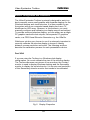
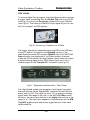
The videoEyetrace Window
Start videoEyetrace by clicking on the videoEyetrace icon, or via
the Windows Start menu. The main window provides a readymade user interface for the Toolbox (see Fig 22 below). The
buttons on the menu bar and tool bar are used to control the type
of stimulus displayed, how the data is collected and how the test
subject is calibrated.
toolbar
pupil position
video window
mimic window
pupil diameter
Fig 22. videoEyetrace Main Window
36
Video Eyetracker Toolbox
Initialising the Video Eyetracker Toolbox Camera
videoEyetrace is designed to work with the whole Video
Eyetracker Toolbox family, as well as pre-recorded video .cam
files. Use the Select Video Source option from the File menu to
reveal the following window:
Fig 23. Select Video Source Window
The EyeLock icon allows you to select between the different
cameras and their range of sampling frequencies. If you are
running a 50 Hz system, and your camera was shipped with a
Camera-I label, select Standard Camera-I as you are running an
interlaced video camera. If there is no label, select Standard
Camera as your camera is running in progressive scan mode. If
you have purchased the High-Speed system, select one of the
High-speed Camera options as shown in Fig 23.
Alternatively, if you wish to perform eye tracking on an existing
video .cam file, select the folder icon and use the browse button
to locate the relevant file.
Title bar
The Title bar displays the program control icon, the application
and active protocol names, and the minimise, maximise and close
buttons.
37
Video Eyetracker Toolbox
Program icon
Protocol name
Application name
Fig 24. Title Bar
Menu bar
The Menu bar displays the headings that lead to the menu
controls. These menu controls are permanently available with the
exception of the Save tab which is disabled if the current data has
already been saved. As with most Windows programs, the menu
buttons are grouped together depending upon their functionality
and organised under more generic menu headings.
file management menu buttons
stimulus presentation and calibration menu buttons
access options window and graph scaling menu buttons
Fig 25. Menu Bar
Toolbar
The tool bar contains buttons that duplicate the functions of the
more frequently used menu options. The main purpose of the tool
bar is to provide quick and easy access to these menu controls.
New protocol Save protocol
Open protocol
and data file
View options
window
Calibrate subject
Load
stimulus
Run stimulus presentation
Trace zoom
in/out
Fig 26. Toolbar
38
Stop stimulus
presentation
Video Eyetracker Toolbox
Data windows
videoEyetrace outputs eye tracking results using two data
windows. The upper data window outputs the tracked eye
positions in graphical form using the horizontal axis to represent
time and the vertical axis to represent eye position. During
tracking, the graph displays two traces showing how the
horizontal and vertical components of eye position vary with time.
Untracked sections caused by blinking or looking outside the
legitimate viewing range are denoted by a yellow trace
superimposed on the horizontal time axis.
Fig 27. videoEyetrace Eye Tracking Graph
The lower data window, which shares the same horizontal time
axis, plots the calculated pupil width for each tracked frame plus a
digital input trace if timing signals are used.
Fig 28. videoEyetrace Pupil Diameter and Digital IO Graph
39
Video Eyetracker Toolbox
During tracking, both graphical outputs will automatically scroll
forwards and can be zoomed in or out, either horizontally or
vertically, using the following toolbar icons:
Fig 29. Zoom Icons
Status bar
The Status bar displays information about videoEyetrace. The first
section of the status bar displays the name of the currently
selected stimulus and the second section displays the name of
the data file currently being shown on in the data window. The
second section of the status bar will stay empty until either data
has been collected or a data file has been opened.
currently selected stimulus
name of current data file
Fig 30. Status Bar
Changing Stimuli and Settings
The presentation stimulus can be controlled or modified using the
Stimulus window. This can be accessed by either clicking on the
Mona Lisa icon on the Toolbar or by clicking View|Stimulus from
the Menu bar.
Fig 31. videoEyetrace Stimulus Icon
40
Video Eyetracker Toolbox
Fig 32. videoEyetrace Stimulus Window
The window shown in Fig 32 controls the type of stimulus
presented to the subject. The currently selected stimulus is
displayed in the stimulus combo box located in the Stimulus
Selection area of the tab. Different stimuli can be chosen by
clicking on the down arrow to the right of the combo box and
selecting a new stimulus from the list. Fig 32 shows that there are
3 stimulus options available if you are using a VSG and a Still
Picture option if you are in dual VGA mode.
Once the required stimulus has been selected its parameters can
be edited by clicking on the Properties button to the right of the
Stimulus combo box. The background colour used for the stimuli
is displayed in the colour panel (remember this colour is not
gamma corrected) and can be edited by either double clicking in
the colour panel or clicking on the browse button to the right of the
panel.
Changing View Options
Click on the View Options icon on the toolbar:
Fig 33. videoEyetrace View Options Icon
41
Video Eyetracker Toolbox
to display the window shown in Fig 34:
Fig 34. Video Eyetracker Options – Graph Tab
Once the stimulus has been selected, the Options window
contains everything else necessary to configure your
experimental setup. This window has four different tabs: Graph,
Configuration, Mimic Window and EIB.
Graph Tab
Clicking on the Graph tab (see Fig 34) will reveal the following
options.
The Results sub window allows videoEyetrace to return the
viewed screen position either in millimetres or in Fick or Helmholtz
angle co-ordinates (see Appendix F for further details). The
Appearance sub window displays the current settings for all
graphical traces which can be customised by clicking on the
appropriate browse icons. The EIB Trig ADC input trigger trace is
42
Video Eyetracker Toolbox
only available for the High-Speed system. See page 54 for further
details.
Configuration Tab
Fig 35. Video Eyetracker Options – Configuration Tab
The Configuration tab displays a set of configuration settings
covering visual warnings and the option to record the video
stream to file. In addition, you can control the minimum duration
necessary to identify a fixation and choose the type of field
separator in the results data file. The last option box controls
whether the tracked status in each image is recorded in the
results file as either an alphabetic “Yes-No” or binary “1-0” format.
Mimic Tab
The Mimic tab controls how the measured eye tracking trace is
presented in the Mimic window. The top dialog box controls the
43
Video Eyetracker Toolbox
amount of time that the trace will persist before disappearing. This
is set, by default, to 5 seconds duration but can be altered
accordingly. The second dialog box controls whether the trace
should persist with constant or fading intensity for the prescribed
duration.
Fig 36. Video Eyetracker Options – Mimic Tab
The third box controls the type of information to be plotted on the
Mimic window. This can be set to map out eye motion, eye
fixations, or both. Eye fixations are represented as circles where
the centres represent eye position and the radii represent
duration. The last 2 boxes control the motion trace and fixation
colours.
EIB Tab (High-Speed System only)
The EIB tab allows you to configure the High-Speed Eyetracker
Interface Box. The first sub-window allows you to disable the
LEDs on the Eyetracker Interface Box front panel if, for example,
their light output could possibly interfere with the experiment. The
44
Video Eyetracker Toolbox
second sub-window controls the signal output for the detected
eye position. This can be either 0.01 volts per mm, 0.001 volts per
mm, or 0.1 volt per degree in either Fick or Helmholtz angular coordinates.
Fig 37. Video Eyetracker Options – EIB Tab
Eye Tracking
Once the calibration procedure is complete and a stimulus has
been loaded, press the Run icon on the Toolbar to enter tracking
mode:
Fig 38. Run Icon
45
Video Eyetracker Toolbox
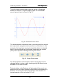
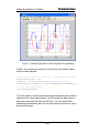
This will initiate tracking and output the results in the graph
window in real time. A typical graph output for a sinusoidal
smooth pursuit task is shown in Fig 39:
Fig 39. Smooth Pursuit Task
The horizontal axis represents time in seconds while the vertical
axis represents eye gaze screen position in millimetres. In this
example, the target was moving horizontally which is indicated
here by the sinusoidal red (horizontal) trace while the vertical
(blue) trace represents biological and system noise.
Fig 40. Graph Zoom Icons
The horizontal and vertical scales of the output graph can be
changed before, during or after tracking using the above icons
available on the main toolbar.
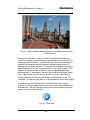
During tracking, videoEyetrace will also project the recent eye
positions into the mimic window and will detect and display any
fixations as circles with radii proportional to their duration. A
typical example of this is shown in Fig 41
46
Video Eyetracker Toolbox
Fig 41. Mimic window showing locus of tracked eye positions
and fixations
During tracking, the Toolbox is able to accommodate fast eye
rotations, sudden head movement and changes in pupil size. By
imaging in the infrared, it is also relatively immune to changes in
ambient illumination and can accommodate a wide range of
spectacles or contact lenses. The system is intelligent enough to
know whether or not an eye is present in the video images. This
subject is therefore free to blink or take breaks between eye
tracking tests, if necessary, without the need to recalibrate each
time. The system can return eye position in Fick, Helmholz or
screen position in millimetres and will automatically return “Not
Tracked” if it detects that an eye is not present in the video image.
videoEyetrace will automatically terminate saccade, smooth
pursuit or bitmap image tasks at the end of their defined duration.
Alternatively, any eye tracking task can be terminated using the
stop icon on the main toolbar:
Fig 42. Stop Icon
47
Video Eyetracker Toolbox
Saving and Loading
videoEyetrace can save and load Data files. These can be saved
and opened either via the File menu or the Save and Open
buttons on the toolbar.
Data Files (*.ved)
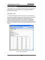
The default videoEyetrace data files are text files containing all
the results collected from an eye tracking experiment. The header
section summarises the experiment in terms of the type of
stimulus used and the duration of the experiment. The header
section also states the position of the first line of tracked eye
position and pupil diameter data. This results data is delimited so
that it may be readily imported into an Excel worksheet, as shown
below.
Fig 43. Results Data File
48
Video Eyetracker Toolbox
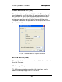
Custom Results Data File (*.ved)
The custom data file option, available from the File menu, can be
used to deselect any of the default file entries shown in Fig 43. It
also provides an option to modify the field separator character
and include a time field, if required. This field is expressed in
milliseconds and starts at zero for the first results data entry.
Temporal quantisation is dependant on the sampling rate of your
Selected Video Source.
Fig 44. Custom Data File Options Window
MATLAB Data File (*.mat)
The results data file can also be saved as a MATLAB .mat format
from the File menu.
Mimic Image (*.bmp)
The Mimic image window, complete with mimic trace, can be
saved as a Bitmap image from the File menu.
49
Video Eyetracker Toolbox
50
Video Eyetracker Toolbox
In this section…
Synchronisation – 50 Hz Systems
Synchronisation – High-Speed Systems
Eyetracker Interface Box – Inputs
CRS ViSaGe
CRS VSG2/5
Eyetracker Interface Box – Outputs
52
54
54
55
56
57
Video Eyetracker Toolbox and MATLAB
57
Worked MATLAB Eye Tracking Examples
Example 1: Bitmap Stimulus with Dual VGA
Example 2: Triggered Saccade Stimulus with VSG
58
58
68
51
Video Eyetracker Toolbox
Synchronisation – 50 Hz Systems
The cable supplied with your Video Eyetracker Toolbox
terminates with a 9 pin D-type connector and a 25 pin D-type
connector. The 9 pin connector attaches to the Picolo frame
grabber and the 25 pin connector to a Digital I/O port on either a
VSG2/5 Feature Connector or a ViSaGe as shown in Fig 45
Fig 45. 25 pin Digital I/O on ViSaGe (Left) and VSG2/5 (Right)
Note: It is not necessary to connect the 25 pin D-type end of the
cable unless you are planning to synchronise the data collected
by the Toolbox with your stimulus presentation system.
Fig 46. Cable Connections for Triggering
52
Video Eyetracker Toolbox
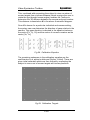
The Toolbox’s video capture card has four digital I/O lines. The
first three (least significant) of these lines are set as input lines
and their states are read every frame. Thus, it is possible to feed
in three independent signals that will be read by the Toolbox
every frame. In order to guarantee that your trigger values are
read by the Toolbox they should last for at least a frame length as
4
the Toolbox only samples the lines once every frame . If you are
using a VSG, it is advisable to create stepped, rather than pulsed,
triggers which are only modified when the stimulus changes. (See
the Library Topics section on Triggering in the Documentation
supplied in your vsgDesktop for further details.)
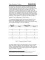
The combined values for these three lines are returned to your
program as the DigitalIO parameter in the data set for each
frame. Fig 47 displays the possible values for this parameter and
the corresponding states of the three channels.
DigitalIO
Value
Line 2
Channel State
Line 1
Line 0
0
0
0
0
1
0
0
1
2
0
1
0
3
0
1
1
4
1
0
0
5
1
0
1
6
1
1
0
7
1
1
1
Fig 47. Combined Digital I/O Values
The fourth digital I/O line is an output trigger. This line is set high
whilst the Toolbox is tracking and low when the Toolbox is not
tracking. Fig 48 describes the inter-connections for the four digital
I/O lines between the 25-way D-type connector and the digital I/O
lines of a ViSaGe or VSG2/5.
4
When changing the state of a line it is good practice to allow for a transition period so that it
becomes impossible for a line to be read at the precise moment that it is being set.
53
Video Eyetracker Toolbox
Digital I/O
Line
Pin on 25-way D-type
Connector
ViSaGe or VSG2/5
I/O Line
0
7
DOUT 6
1
8
DOUT 7
2
9
DOUT 8
3
21
DIN 7
Fig 48. Digital I/O Pin-Out Details
Synchronisation – High-Speed Systems
Eyetracker Interface Box -- Inputs
The High-Speed system must be used in conjunction with the
Eyetracker Interface Box (EIB). Details of how to connect this are
available in the Hardware Installation section of the High-Speed
Video Eyetracker Toolbox Installation Manual.
Fig 49. Connections to Camera, EIB and PC
54
Video Eyetracker Toolbox
CRS ViSaGe
To receive digital timing triggers, the High-Speed system requires
a trigger cable connecting from the Digital Trig port on your EIB
(see Fig 51) to the 5 pin Accessory connector on your ViSaGe
(see Fig 50). This frees up ViSaGe’s 25 pin digital IO port for use
with, for example, an EEG system.
Fig 50. Accessory Connector on ViSaGe
The trigger signals are transmitted from the EIB via its USB port
to the PC where it is logged in the DigitalIO column of the
videoEyetrace results file, and the digitalIO field in the MATLAB
Data structure (see Appendix G for further details). However,
unlike the 50 Hz system, the High-Speed version does not output
a digital tracking signal to the VSGs Digital Input line 7 but is
instead output on the Tracked BNC connector (see Fig 53).
Fig 51. Eyetracker Interface Box – Rear Panel
The High-Speed system can accept an input trigger from other
external devices via the Trig In BNC connector on the EIB front
panel (see Fig 53). This input can be a TTL or analogue voltage
signal within the range of ±5 volts. In the MATLAB Data results
structure, the values are returned in the trigIn field and are in the
range of ±1. This input also appears in videoEyetrace as the EIB
Trig ADC graphical plot and is also logged as part of the .ved
results data file.
55
Video Eyetracker Toolbox
CRS VSG 2/5
The High-Speed system can receive digital timing triggers from a
VSG2/5 visual stimulus generator. The supplied trigger cable
connects from the Digital Trig port on your EIB (Fig 51) to the 25
pin Digital I/O port on your Feature Connector (Fig 52) or BNC
Breakout Box. This input can also be three TTL digital voltage
signals (0 or 5 volts).
The trigger signals are transmitted from the EIB via its USB port
to the PC where it is logged in the Digital I/O column of the
videoEyetrace results file, and the digitalIO field in the MATLAB
Data structure (see Appendix G for further details). However,
unlike the 50 Hz system, the High-Speed version does not output
a digital tracking signal to the VSG’s Digital Input line 7 but is
instead output on the Tracked BNC connector (see Fig 53).
The High-Speed system can accept an input trigger from other
external devices via the Trig In BNC connector on the EIB front
panel (see Fig 53). This input can be a TTL or analogue voltage
signal within the range of ±5 volts. In the MATLAB Data results
structure, the values are returned in the trigIn field and are in the
range of ±1. This input also appears in videoEyetrace as the EIB
Trig ADC graphical plot and is also logged as part of the .ved
results data file.
Fig 52. 25 pin Digital I/O on VSG2/5
56
Video Eyetracker Toolbox
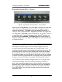
Eyetracker Interface Box -- Outputs
Fig 53. Eyetracker Interface Box – Front Panel
Apart from the Trig IN BNC, the other BNC connectors output the
recorded eye position data which can then be logged using
external equipment. The Pupil output is statically scaled at 0.1
volts per mm of pupil diameter. Trig Out replicates any signal fed
into Trig In and Tracked outputs a standard TTL signal of either 0
or approximately 5 volts. The scales of the X and Y outputs can
be set using the vetSetEIB_XYOutputType command which is
detailed in Appendix A (or within videoEyetrace under the EIB tab
of Graph Options).
Video Eyetracker Toolbox and MATLAB
MATLAB is a data analysis and visualisation application built
around a simple scripting language and is widely used in the
creation of models and in the analysis of experimental results. By
providing tools to help the vision researcher control and analyse
their experiments from a single environment, we hope to reduce
the training burden on new entrants to the field, as well as making
it easier for existing experimenters to integrate their experimental
design and control with their theoretical modelling and analysis.
The Toolbox’s open interface design allows you to integrate eye
tracking functionality with your existing laboratory software or
write new eye tracking applications using a familiar environment.
Because the Toolbox has been designed in this way, all aspects
of its eye tracking functionality can be accessed and controlled
from MATLAB or any windows programming tool that supports
Microsoft COM.
57
Video Eyetracker Toolbox
In particular, MATLAB’s relatively simple and concise scripting
environment has gained a widespread following among the vision
research community. As a result, MATLAB is now the default
software environment for which Cambridge Research Systems
provides support. What follows are two worked examples which
demonstrate the simplicity of using the Video Eyetracker Toolbox
from within MATLAB.
The commands that make up the Video Eyetracker Toolbox
interface for MATLAB are detailed in Appendix A. If you want to
use a different programming tool, you will find more information
about the COM interface in the CRS Support Portal
(www.crsltd.com/support/login).
Worked MATLAB Eye Tracking Examples
The MATLAB scripts discussed in this section are distributed with
the CRS Toolbox for MATLAB which should be downloaded from
the Cambridge Research Systems Support Portal
(www.crsltd.com/support/login) as described in Appendix A.
Example 1: Bitmap Stimulus with Dual VGA
Example 1 is designed to demonstrate basic eye tracker
functionality in a Dual VGA configuration and is suitable for use
with the 50 Hz and High-Speed systems. This example displays a
single bitmap image, calibrates your subject, tracks subsequent
eye positions for 30 seconds, displays the results and finally
saves the collected data to a file.
This demonstration does not require a CRS Visual Stimulus
Generator (VSG) but assumes you are using a dual Windows
display configuration with the Primary output set to your Windows
desktop monitor and the Secondary output set to display the
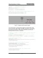
visual stimulus. See the Dual VGA section in the Calibration
Chapter for further details.
Run the demoVET_simpleVGAstimulus.m script. The following
lines of code initialise the Video Eyetracker Toolbox system and
the stimulus display device:
58
Video Eyetracker Toolbox
function demoVET_simpleVGAstimulus
% Declare CRS MATLAB constants
global CRS;
if isempty(CRS); crsLoadConstants; end;
% Set the stimulus device to Dual-VGA.
%(For use with a VSG, use the constant CRS.deVSG)
vetSetStimulusDevice(CRS.deVGA);
% Ask the user to select a video source
errorCode = vetSelectVideoSource(CRS.vsUserSelect);
if(errorCode<0); error('Video Source not selected.');
end;
… which will open the window shown in Fig 54
Fig 54. Camera / Movie File Source Window
Select the Video Eyetracker Camera which corresponds to your
supplied system from the Device Type drop down box. This option
should be highlighted as shown in Fig 54, but if not, click the
EyeLock button to its left. You can select from Standard Camera,
Standard Camera-I or one of the High-Speed options. Once the
correct camera has been selected, click OK to run the following
lines of code which open up the Camera, and Calibration
windows:
% Create a live camera screen so that we can position
% the camera to image the test subject’s eye
vetCreateCameraScreen;
59
Video Eyetracker Toolbox
% Calibrate the subject, and return if
% the user exits before completion.
errorCode = vetCalibrate;
if(errorCode<0); error('Calibration not completed.');
end;
% Clear the VET VGA calibration window.
vetSetDeviceParameters(CRS.deUser);
Once your subject is correctly positioned, click Start in the
Calibration window. The calibration routine will now proceed by
requesting the test subject to fixate on a number of calibration
targets on the stimulus monitor:
Fig 55. Live Camera and Calibration Windows (Calibration in
Progress)
Once calibration is complete, click OK in the subject Calibration
window. The following lines of code will check that Windows has
been configured in dual VGA mode and calculate both monitor
positions.
% Check we have dual-VGA monitor setup
% Calculate primary and secondary monitor positions.
MonitorPos
= get(0, 'MonitorPosition');
if(numel(MonitorPos)<8); error('Less than two monitors
detected.'); end;
60
Video Eyetracker Toolbox
PrimaryPos
= MonitorPos(1,:);
SecondaryPos
= MonitorPos(2,:);
PrimarySize
= [PrimaryPos(3) - PrimaryPos(1),
PrimaryPos(4) - PrimaryPos(2)] + 1;
SecondarySize
= [SecondaryPos(3) SecondaryPos(1),SecondaryPos(4)-SecondaryPos(2)] + 1;
PrimaryLowerLeft
= [PrimaryPos(1),
((SecondarySize(2) - PrimaryPos(2))
- PrimarySize(2)) + 2];
SecondaryLowerLeft = [SecondaryPos(1),
((PrimarySize(2)
- SecondaryPos(2)) PrimarySize(2)) + 2];
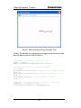
The following lines of code will then display the dialogue box as
shown in Fig 56 and await a user response
% Display a dialog to select the stimulus display.
MonitorToUse = uigetpref('Monitors','One', ...
'Stimulus Monitor Selection Dialog', ...
'Select which monitor to use.', {'1','2'}, ...
'CheckboxString','Always use this monitor.');
switch MonitorToUse;
case '1'
SelectedPos = [PrimaryLowerLeft, PrimarySize ];
case '2'
SelectedPos = [SecondaryLowerLeft,SecondarySize];
end
Fig 56. Select Stimulus Monitor
Select the appropriate monitor by clicking the relevant button. The
following lines of code will now display the stimulus image on the
chosen stimulus monitor:
61
Video Eyetracker Toolbox
% Pick a stimulus image, and get the full path to the
% file. (The image file must be on your MATLAB path).
ImageFile = which('Glasgow.bmp');
% Read the selected image file, getting both the image
% and the palette data.
[Image,Palette] = imread(ImageFile);
% Create a figure window to display the stimulus
% Load the bitmap image onto the selected monitor,
% scaling appropriately.
Figure1Handle = figure(1); AxesHandle = axes;
set(AxesHandle, 'Position', [0 0 1 1]);
set(Figure1Handle, 'MenuBar',
'none','ToolBar','none','Position',SelectedPos);
imagesc(Image);
colormap(Palette);
axis('off');
The same stimulus image will now be loaded onto a Mimic screen
on your Windows monitor:
% Create Mimic Screen and load Bitmap image
vetCreateMimicScreen;
vetSetMimicScreenDimensions(400, 0, 400, 300);
vetSetFixationPeriod(300);
vetSetFixationRange(10);
vetSetMimicPersistenceType(CRS.ptMotionAndFixations);
vetLoadBmpFileToMimicScreen(ImageFile,1);
Notice that the Mimic screen has been set to show any fixations
which last for at least 300 milliseconds within a 10mm cluster. The
Toolbox will now track for 30 seconds. All eye movements and
fixations will be output to the Mimic window as shown in Fig 57:
% Track for 30 seconds, then stop tracking
vetClearDataBuffer;
vetStartTracking;
pause(30);
vetStopTracking;
% Tidy up by clearing away camera and mimic screens.
vetDestroyCameraScreen;
vetDestroyMimicScreen;
close(figure1Handle);
62
Video Eyetracker Toolbox
Fig 57. Mimic Window with Motion and Fixations Trace
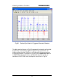
The tracked results will now be plotted in Fick angular coordinates
with longitude in blue and latitude in red. Some example results
are shown in Fig 58
% Retrieve the recorded eye positions
% without removing them from the buffer.
Remove = false;
DATA = vetGetBufferedEyePositions(Remove);
% Display the retrieved positions
figure(2); cla; hold on;
plot(DATA.fickPositions(:,1),'b'); %Longitude in blue
hold on;
plot(DATA.fickPositions(:,2),'r'); %Latitude in red
grid on;
63
Video Eyetracker Toolbox
Fig 58. Tracked Eye Data in Fick Angular Co-ordinates
Finally, the results are saved to disk and the eye position data
buffer is then deleted:
% Save the results to disk as a comma delimited file.
CurrentDirectory = cd;
tempfile = [CurrentDirectory,'\myResults.csv'];
vetSaveResults(tempfile, CRS.ffCommaDelimitedNumeric);
% Clear the data buffer.
vetClearDataBuffer;
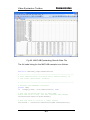
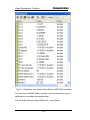
This will create a comma delimited results data file which can be
imported into other applications. Fig 59 shows the data when it
has been imported into Microsoft Excel. You can see all the
calibration parameters plus the full eye tracking results for every
processed image:
64
Video Eyetracker Toolbox
Fig 59. MATLAB Eyetracking Results Data File
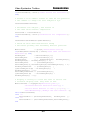
The full code listing for this MATLAB example is as follows:
function demoVET_simpleVGAstimulus
% ---------------------------------------------------% This demonstrates the most basic functionality of
% the Video Eyetracker Toolbox.
% ---------------------------------------------------% Declare CRS MATLAB constants
global CRS;
if isempty(CRS); crsLoadConstants; end;
% Set the stimulus device to Dual-VGA.
%(For use with a VSG, use the constant CRS.deVSG)
vetSetStimulusDevice(CRS.deVGA);
% Ask the user to select a video source
errorCode = vetSelectVideoSource(CRS.vsUserSelect);
65
Video Eyetracker Toolbox
if(errorCode<0); error('Video Source not selected.');
end;
% Create a live camera screen so that we can position
% the camera to image the test subject’s eye
vetCreateCameraScreen;
% Calibrate the subject, and return if
% the user exits before completion.
errorCode = vetCalibrate;
if(errorCode<0); error('Calibration not completed.');
end;
vetSetDeviceParameters(CRS.deUser);
% Check we have dual-VGA monitor setup
% Calculate primary and secondary monitor positons.
MonitorPos
= get(0, 'MonitorPosition');
if(numel(MonitorPos)<8); error('Less than two monitors
detected.'); end;
PrimaryPos
= MonitorPos(1,:);
SecondaryPos
= MonitorPos(2,:);
PrimarySize
= [ PrimaryPos(3)- PrimaryPos(1),
PrimaryPos(4)- PrimaryPos(2)] + 1;
SecondarySize
= [SecondaryPos(3)SecondaryPos(1),SecondaryPos(4)-SecondaryPos(2)] + 1;
PrimaryLowerLeft
= [PrimaryPos(1) ,
((SecondarySize(2) - PrimaryPos(2))
PrimarySize(2)) + 2];
SecondaryLowerLeft = [SecondaryPos(1),
((PrimarySize(2)
- SecondaryPos(2)) PrimarySize(2)) + 2];
% Display a dialog to allow the user to select the
% stimulus display that they wish to use.
MonitorToUse = uigetpref('Monitors','One', ...
'Stimulus Monitor Selection Dialog', ...
'Select which monitor to use.', {'1','2'}, ...
'CheckboxString','Always use this monitor.');
switch MonitorToUse;
case '1'
SelectedPos = [PrimaryLowerLeft, PrimarySize ];
case '2'
SelectedPos = [SecondaryLowerLeft,SecondarySize];
end
66
Video Eyetracker Toolbox
% Pick an image file to display, and get the full path
% to the file.
% (The image file must be on your MATLAB path).
ImageFile = which('Glasgow.bmp');
% Read the selected image file, getting both the image
% and the palette data.
[Image,Palette] = imread(ImageFile);
% Create a figure window in which to display the
% stimulus, then stimulus on the figure window,
% Load the bitmap image onto the selected monitor,
% scaling appropriately.
Figure1Handle = figure(1); AxesHandle = axes;
set(AxesHandle, 'Position', [0 0 1 1]);
set(Figure1Handle, 'MenuBar',
'none','ToolBar','none','Position',SelectedPos);
imagesc(Image);
colormap(Palette);
axis('off');
% Create Mimic Screen and load Bitmap image
vetCreateMimicScreen;
vetSetMimicScreenDimensions(400, 0, 400, 300);
vetSetFixationPeriod(300);
vetSetFixationRange(10);
vetSetMimicPersistenceType(CRS.ptMotionAndFixations);
vetLoadBmpFileToMimicScreen(ImageFile,1);
% Start tracking.
vetClearDataBuffer;
vetStartTracking;
% Track for 30 seconds, then stop tracking
pause(30);
vetStopTracking;
% Tidy up by clearing away the camera and mimic
% screens.
vetDestroyCameraScreen;
vetDestroyMimicScreen;
close(figure1Handle);
% Retrieve the recorded eye positions
% without removing them from the buffer.
Remove = false;
DATA = vetGetBufferedEyePositions(Remove);
67
Video Eyetracker Toolbox
% Display the retrieved positions
figure(2); cla; hold on;
plot(DATA.fickPositions(:,1),'b'); %Longitude in blue
hold on;
plot(DATA.fickPositions(:,2),'r'); %Latitude in red
grid on;
% Save the results to disk as a comma delimited file.
CurrentDirectory = cd;
tempfile = [CurrentDirectory,'\myResults.csv'];
vetSaveResults(tempfile, CRS.ffCommaDelimitedNumeric);
% Clear the data buffer.
vetClearDataBuffer;
Example 2: Triggered Saccade Stimulus for ViSaGe
Example 2 is specifically designed to demonstrate how the HighSpeed system can be integrated with a Cambridge Research
Systems ViSaGe for a typical oculomotor research application.
This example calibrates a test subject, generates a series of
fixation and saccade targets and tracks the subject’s eye
positions. The eye movement results and stimulus timing triggers
are then displayed as a graph and saved to a file.
The first section of code initialises the ViSaGe, selects the video
source, creates Camera and Mimic windows and performs
calibration as in the previous MATLAB example.
function demoVETsacc1
% A simple VET demo to elicit reflexive horizontal
% saccades. This demo requires a ViSaGe
% --------------------------------------------------global CRS;
crsLoadConstants;
Check we are running on a VSG ViSaGe
CheckCard = crsGetSystemAttribute(CRS.DEVICECLASS);
if(CheckCard ~= 7)
error('Sorry, this demonstration requires a VSG
ViSaGe.'); end;
% Select the VET camera to use.
vetSetStimulusDevice(CRS.deVSG);
errorCode = vetSelectVideoSource(CRS.vsUserSelect);
if(errorCode<0); error('Video Source not selected.');
end;
68
Video Eyetracker Toolbox
% Calibrate the video eyetracker
vetCreateCameraScreen;
errorCode = vetCalibrate;
if(errorCode<0); error('Calibration not completed.');
end;
% Create the Mimic Screen window
vetCreateMimicScreen;
vetSetMimicScreenDimensions(400, 0, 400, 300);
vetSetFixationPeriod(300);
vetSetFixationRange(10);
vetSetMimicPersistenceType(CRS.ptMotionAndFixations);
Fig 60. 250 Hz Live Camera and Calibration Windows
(Calibration in Progress)
The next section of code defines the colours, size and shape of all
stimuli and draws the stimuli into video memory. In this example
we have chosen a green circle as the fixation target and red
circles as saccade targets. All circles have a viewed diameter of
0.3 degrees.
% Set the palette and pen levels for drawing red and
% green dots on a mean grey background.
GreyLevel = 1; GreyRGB = [0.5, 0.5, 0.5];
crsPaletteSetPixelLevel(GreyLevel, GreyRGB );
RedLevel
= 2; RedRGB
= [1.0, 0.0, 0.0];
crsPaletteSetPixelLevel(RedLevel,
RedRGB );
GreenLevel = 3; GreenRGB = [0.0, 1.0, 0.0];
crsPaletteSetPixelLevel(GreenLevel, GreenRGB);
69
Video Eyetracker Toolbox
% Draw the fixation point and target on their
% respective video pages, whilst displaying a blank
% page to 'hide' the drawing
TargetSize = crsDegreesToPixels([0.3,0.3]);
BlankPage
= 1;
crsClearPage( BlankPage,
GreyLevel );
FixationPage = 2;
crsClearPage( FixationPage,GreyLevel );
TargetPage
= 3;
crsClearPage( TargetPage, GreyLevel );
crsSetDisplayPage(BlankPage);
% Draw a green fixation point on the fixation page
crsSetDrawPage(FixationPage);
crsSetPen1(GreenLevel);
crsDrawOval([0,0],TargetSize);
% Draw a red target on the target page
crsSetDrawPage(TargetPage);
crsSetPen1(RedLevel);
crsDrawOval([0,0],TargetSize);
The next section of code defines the randomised timings and
locations of the fixation and saccade target stimuli. This is
designed to prevent the test subject from anticipating the position
or timing of the next stimulus. This test will present a total of 10
horizontal fixation and saccade targets with displacements of 0
(fixation) 5, 7.5 and 10 degrees.
% Specify the timing for one trial.
% We use a 1 - 3 second random interval to elicit
% reflexive, rather than predictive saccades.
PageOrder = [FixationPage,TargetPage,FixationPage];
MinTime
= crsSecondsToFrames([ 0.5, 1, 0.5]);
MaxTime
= crsSecondsToFrames([ 1.5, 3, 1.5]);
% Replicate the trials to provide data for all trials
NumTrials = 10;
Pages
= repmat(PageOrder,1,NumTrials);
MinTime
= repmat(MinTime, 1,NumTrials);
MaxTime
= repmat(MaxTime, 1,NumTrials);
Times
= round(MinTime + (rand .* (MaxTimeMinTime)));
% Specify target locations from 5 to 10 degrees (We
% invert the x and y locations because we are moving
% the video window offset, not the video memory).
Xlocations = -crsDegreesToPixels([ 5.0, 7.5, 10.0]);
Ylocations = -crsDegreesToPixels([ 0.0, 0.0, 0.0]);
70
Video Eyetracker Toolbox
% Generate random locations for each entry.
Indices
= ceil(rand(size(Pages)) .*
numel(Xlocations));
Xlocations = Xlocations(Indices);
Ylocations = Ylocations(Indices);
% Make sure the fixation point always appears at 0,0
Xlocations(Pages==FixationPage) = 0;
Ylocations(Pages==FixationPage) = 0;
Fig 61. Fixation and Saccade Targets
The next section of code defines triggers and associates them
with the relevant video pages. We then commence eye tracking
and present the stimuli. The Camera and Mimic screens are
destroyed when the test is complete.
% Specify triggers to identify when a target shift has
% occurred.
% (The VET captures digital output lines 6, 7 and 8).
Triggers = zeros(size(Pages));
Triggers(Pages~=FixationPage) = bin2dec('011100000');
% Set up RTS page cycling.
Repeating = false;
crsSimplePageCycle(Pages,Xlocations,Ylocations,Times,T
riggers,Repeating);
% Start eye tracking and stimulus cycling.
vetStartTracking;
crsSetCommand(CRS.CYCLEPAGEENABLE);
pause(crsFramesToSeconds(sum(Times(:))));
crsSetDisplayPage(BlankPage);
vetStopTracking;
% Tidy up by clearing away the camera screen.
vetDestroyCameraScreen;
vetDestroyMimicScreen;
71
Video Eyetracker Toolbox
Fig 62. Mimic Window during Saccade Test
Finally, the tracked eye positions and triggering results are plotted
and the data is saved to MATLAB file:
% Retrieve the recorded eye positions
remove = false;
DATA = vetGetBufferedEyePositions(remove);
% Display the eye positions and triggers
g = figure;
plot(DATA.ficksPositions(:,1),'b'); % longitude in blue
hold on;
plot(DATA.ficksPositions(:,2),'r'); % latitude in red
hold on;
plot(DATA.digitalIO,'g'); % triggers in green
grid on;
% Finally, save the results to disk as a .mat file.
tempfile = 'C:\myResults.mat';
vetSaveResults(tempfile, CRS.ffMATfile);
72
Video Eyetracker Toolbox
Fig 63. Tracked Eye Data for Triggered Saccade Stimulus
The blue and red traces in Fig 63 represent horizontal and vertical
angular eye movements, while the green trace represents the
triggers output by the ViSaGe to coincide with the presentations
of saccade targets. Furthermore, opening the myResults.mat file
in MATLAB’s current directory, will declare all your results as
variables in MATLAB’s own workspace as shown in Fig 64
73
Video Eyetracker Toolbox
Fig 64. Calibration and Tracked Eye Data as MATLAB Variables
You can now use MATLAB to analyze, plot or process any of your
calibration or recorded eye results data.
The full code listing for demoVETsacc1 is as follows:
74
Video Eyetracker Toolbox
function demoVETsacc1
% A simple VET demo to elicit reflexive horizontal
% saccades.
% This demo requires a CRS ViSaGe
% --------------------------------------------------global CRS;
crsLoadConstants;
Check we are running on a VSG ViSaGe
CheckCard = crsGetSystemAttribute(CRS.DEVICECLASS);
if(CheckCard ~= 7)
error('Sorry, this demonstration requires a VSG
ViSaGe.');
end;
% Select the VET camera to use.
vetSetStimulusDevice(CRS.deVSG);
errorCode = vetSelectVideoSource(CRS.vsUserSelect);
if(errorCode<0); error('Video Source not selected.');
end;
% Calibrate the video eyetracker
vetCreateCameraScreen;
errorCode = vetCalibrate;
if(errorCode<0); error('Calibration not completed.');
end;
% Create the Mimic Screen window
vetCreateMimicScreen;
vetSetMimicScreenDimensions(400, 0, 400, 300);
vetSetFixationPeriod(300);
vetSetFixationRange(10);
vetSetMimicPersistenceType(CRS.ptMotionAndFixations);
% Set the palette and pen levels for drawing red and
% green dots on a mean grey background.
GreyLevel = 1; GreyRGB = [0.5, 0.5, 0.5];
crsPaletteSetPixelLevel(GreyLevel, GreyRGB );
RedLevel
= 2; RedRGB
= [1.0, 0.0, 0.0];
crsPaletteSetPixelLevel(RedLevel,
RedRGB );
GreenLevel = 3; GreenRGB = [0.0, 1.0, 0.0];
crsPaletteSetPixelLevel(GreenLevel, GreenRGB);
% Draw the fixation point and target on their
% respective video pages, whilst displaying a blank
% page to 'hide' the drawing
TargetSize = crsDegreesToPixels([0.3,0.3]);
BlankPage
= 1;
crsClearPage( BlankPage,
GreyLevel );
FixationPage = 2;
crsClearPage( FixationPage,GreyLevel );
75
Video Eyetracker Toolbox
TargetPage
= 3;
crsClearPage( TargetPage, GreyLevel );
crsSetDisplayPage(BlankPage);
% Draw a green fixation point on the fixation page
crsSetDrawPage(FixationPage);
crsSetPen1(GreenLevel);
crsDrawOval([0,0],TargetSize);
% Draw a red target on the target page
crsSetDrawPage(TargetPage);
crsSetPen1(RedLevel);
crsDrawOval([0,0],TargetSize);
% Specify the timing for one trial.
% We use a 1 - 3 second random interval to elicit
% reflexive, rather than predictive saccades.
PageOrder = [FixationPage,TargetPage,FixationPage];
MinTime
= crsSecondsToFrames([ 0.5, 1, 0.5]);
MaxTime
= crsSecondsToFrames([ 1.5, 3, 1.5]);
% Replicate the trials to provide data for all trials
NumTrials = 10;
Pages
= repmat(PageOrder,1,NumTrials);
MinTime
= repmat(MinTime, 1,NumTrials);
MaxTime
= repmat(MaxTime, 1,NumTrials);
Times
= round(MinTime + (rand .* (MaxTimeMinTime)));
% Specify target locations from 5 to 10 degrees.(We
% invert the x and y locations because we are moving
% the video window offset, not the video memory).
Xlocations = -crsDegreesToPixels([ 5.0, 7.5, 10.0]);
Ylocations = -crsDegreesToPixels([ 0.0, 0.0, 0.0]);
% Generate random locations for each entry.
Indices
= ceil(rand(size(Pages)) .*
numel(Xlocations));
Xlocations = Xlocations(Indices);
Ylocations = Ylocations(Indices);
% Make sure the fixation point always appears at 0,0
Xlocations(Pages==FixationPage) = 0;
Ylocations(Pages==FixationPage) = 0;
% Specify triggers to identify when a target shift has
% occurred.
% (The VET captures digital output lines 6, 7 and 8).
Triggers = zeros(size(Pages));
Triggers(Pages~=FixationPage) = bin2dec('011100000');
76
Video Eyetracker Toolbox
% Set up RTS page cycling.
Repeating = false;
crsSimplePageCycle(Pages,Xlocations,Ylocations,Times,T
riggers,Repeating);
% Start eyetracking and stimulus cycling.
vetStartTracking;
crsSetCommand(CRS.CYCLEPAGEENABLE);
pause(crsFramesToSeconds(sum(Times(:))));
crsSetDisplayPage(BlankPage);
vetStopTracking;
% Tidy up by clearing away the camera screen.
vetDestroyCameraScreen;
vetDestroyMimicScreen;
% Retrieve the recorded eye positions
remove = false;
DATA = vetGetBufferedEyePositions(remove);
% Display the eye positions and triggers
g = figure;
plot(DATA.ficksPositions(:,1),'b'); % longitude in blue
hold on;
plot(DATA.ficksPositions(:,2),'r'); % latitude in red
hold on;
plot(DATA.digitalIO,'g'); % triggers in green
grid on;
% Finally, save the results to disk as a .mat file.
tempfile = 'C:\myResults.mat';
vetSaveResults(tempfile, CRS.ffMATfile);
77
Video Eyetracker Toolbox
In this section…
Appendix A MATLAB Toolbox Commands
81
Appendix B Imaging and Illumination Geometry
122
Appendix C Template for Fixed Mount EyeLock
127
Appendix D System Specification
129
Appendix E Hot Mirror Frequency Response
131
Appendix F Fick and Helmholtz Coordinates
133
Appendix G Data Returned by the Toolbox
135
Appendix H Troubleshooting
137
Notes
147
79
Video Eyetracker Toolbox
80
Video Eyetracker Toolbox
The Video Eyetracker Toolbox can be controlled using MATLAB
or any Windows programming tool that supports Microsoft COM.
The CRS Toolbox for MATLAB contains the commands you need
to use to control the Video Eyetracker Toolbox. To download the
CRS Toolbox for MATLAB, login to the CRS Support Portal
(www.crsltd.com/support/login).
What follows is a listing of the functions that make up the
MATLAB interface and the ways in which they can be used. A
description of the COM programming interface and additional
demonstrations are available from the Cambridge Research
Systems support portal (www.crsltd.com/support/login).
81
Video Eyetracker Toolbox
Functions
vetAddRegion
vetCalibrate
vetCalibrateAdvanced
vetClearAllRegions
vetClearDataBuffer
vetClearMimicScreenBitmap
vetCreateCameraScreen
vetCreateMimicScreen
vetDeleteRegion
vetDestroyCameraScreen
vetDestroyMimicScreen
vetGetActiveRegion
vetGetBufferedEyePositions
vetGetCalibrated
vetGetEIBLEDsEnabled
vetGetEIB_XYOutputType
vetGetFixationLocation
vetGetLatestEyePosition
vetGetMimicScreenBitmap
vetGetPupilCalibrated
vetGetRegionCount
vetGetResultsCount
vetGetTracking
vetGetToolboxVersion
vetGetVideoSourceFile
vetGetVideoSourceType
vetIsEyeDataAvailable
vetLoadBmpFileToMimicScreen
vetLoadCalibrationFile
vetLoadBitmapToMimicScreen
vetSaveCalibrationFile
vetSaveMimicScreenBitmap
vetSaveResults
vetSelectVideoSource
vetSetCameraScreenDimensions
vetSetDeviceParameters
82
84
85
86
87
88
88
88
89
89
90
90
90
91
93
93
93
94
95
96
96
97
97
98
98
98
99
100
100
101
102
102
103
103
104
106
106
Video Eyetracker Toolbox
vetSetEIBLEDsEnabled
vetSetEIB_XYOutputType
vetSetFixationPeriod
vetSetFixationRange
vetSetMimicBackgroundColor
vetSetMimicFixationColor
vetSetMimicPersistence
vetSetMimicPersistenceStyle
vetSetMimicPersistenceType
vetSetMimicScreenDimensions
vetSetMimicTraceColor
vetSetStimulusDevice
vetSetUIMonitor
vetSetViewingDistanceMM
vetStartRecordingToFile
vetStartTracking
vetStopRecording
vetStopTracking
107
108
108
109
110
110
111
111
112
113
113
114
115
115
116
116
117
117
Events
vetSetCallbackClearDisplay
vetSetCallbackCollectResults
vetSetCallbackDrawTarget
vetSetCallbackFixate
vetSetCallbackInitialiseDisplay
vetSetCallbackRegionChanged
117
118
119
119
120
120
83
Video Eyetracker Toolbox
vetAddRegion
Video Eyetracker Toolbox Regions-Of-Interest are intended to
assist with fixation monitoring tasks. These regions are defined as
rectangular patches lying in the plane of the stimulus display.
There may be as many regions as you wish, but no two regions
may overlap. Each region has a unique identifying number, called
the regionHandle. If the subject's direction of gaze intersects a
region, that region's identifying number is recorded in the Video
Eyetracker Toolbox data buffer along with all the other eye
position data that is being collected. The currently active region's
RegionHandle can also be obtained using the
vetGetActiveRegion function. When the direction of gaze first
enters a region, the MATLAB function specified using
vetSetCallbackRegionChanged is executed.
MATLAB Syntax
[regionHandle] =
vetAddRegion(leftMM,topMM,rightMM,bottomMM);
Parameters
LeftMM – A rational scalar (1-by-1 matrix), specifying the left edge of
the region of interest.
TopMM – A rational scalar (1-by-1 matrix), specifying the top edge of
the region of interest.
RightMM – A rational scalar (1-by-1 matrix), specifying the right edge of
the region of interest.
BottomMM – A rational scalar (1-by-1 matrix), specifying the bottom
edge of the region of interest.
Return Values
regionHandle - An integer scalar (1-by-1 matrix), denoting the region
created by the operation.
Example
[regionHandle] = vetAddRegion(50, 50, 100, 100);
will add a square Region of Interest 50mm in size with a mid point
75mm right and 75mm up from the centre of the screen.
84
Video Eyetracker Toolbox
See also
vetDeleteRegion, vetClearAllRegions, vetRegionCount,
vetSetCallbackRegionChanged
vetCalibrate
This function launches a calibration dialog that can be used to
configure and control subject calibration. Through this dialog, eye
position and pupil diameter can be calibrated, and calibration
options can be configured. Normally, calibration options are
recalled from the previous session; If specific calibration options
are required, they can be specified using the
vetCalibrateAdvanced function.
The vetCalibrate function will display targets on either a
Secondary Windows VGA display, or on a VSG, depending on the
stimulus device that has been selected using the
vetSetStimulusDevice function.
If a 'user' stimulus device has been selected, then it is up to the
user to draw fixation targets on their stimulus device, under the
control of user- specifiable callbacks. You can specify these
callbacks using the following functions:
vetSetCallbackInitialiseDisplay, vetSetCallbackClearDisplay,
vetSetCallbackDrawTarget. User device parameters also need
to be set using the vetSetDeviceParameters function.
NOTE: You must select the video source and the stimulus device
before calling vetCalibrate. See demoVETQuickstart for a
worked example.
MATLAB Syntax
vetCalibrate;
See also
vetCalibrateAdvanced, vetCalibrationStatus,vetSelectVideoSource,
vetStartTracking, vetLoadCalibrationFile, vetSaveCalibrationFile
85
Video Eyetracker Toolbox
vetCalibrateAdvanced
Like vetCalibrate this function can be used to calibrate a subject.
vetCalibrateAdvanced opens the Calibration window but unlike
vetCalibrate it passes a number of parameters to the window
overwriting the Calibration window’s default settings. Thus, this
function makes it possible to perform a non-standard calibration
without using the Advanced Calibration Parameter dialog. This
function returns True (1) if the calibration has been successful,
otherwise will return False (0). If you wish to calibrate a subject
without passing any parameters you should use the Video
Eyetracker Toolbox vetCalibrate function instead.
MATLAB Syntax
calibrationSuccessful =
vetCalibrateAdvanced(xPoints,yPoints,targetShape,
targetSize,targetColour,backgroundColour, ...
scaleFactor,fixationDuration,accuracyLevel, ...
imageFilename);
Parameters
numX – A scalar integer value in the closed interval [2,10] indicating the
number of dots across to use.
numY – A scalar integer value in the closed interval [2,10] indicating the
number of dots down to use.
targetShape – A scalar integer value drawn from the following set:
CRS.tsSquare
CRS.tsCircle
CRS.tsCross
CRS.tsImage
targetSize – A rational scalar value in the closed interval [0.01, 5.0].
This indicates the diameter of the target, measured in degrees of Arc.
This value is ignored when a tsImage is selected.
targetColour – A 3-by-1 or 1-by-3 RGB colour vector, each component
value a rational number in the interval [0, 1].
backgroundColour – A 3-by-1 or 1-by-3 RGB colour vector, each
component value a rational number in the interval [0, 1].
scaleFactor – A scalar value in the interval [1,100], indicating the
calibration area as a percentage of total screen area, a sensible value
for this parameter would be 90%.
86
Video Eyetracker Toolbox
fixationDuration – A scalar value, measured in milliseconds, indicating
how long a fixation needs to last in order to be detected. - A sensible
value for this parameter would be around 500ms.
accuracyLevel – A scalar integer value drawn from the following set:
CRS.acLow
CRS.acMedium
CRS.acHigh
This value indicates how much movement will be tolerated when
detecting a fixation.
imageFilename – A char array. (Matlab string) containing the filename
and full path. This parameter should be set to an empty string if
targetShape has been set to anything other than tsImage.
Example
vetCalibrateAdvanced(3,3,CRS.tsSquare,0.5,[1;0;0],[0;0;1],90,100,
CRS.acMedium,'');
See also
vetCalibrate, vetCalibrationStatus, vetSelectVideoSource,
vetStartTracking, vetLoadCalibrationFile, vetSaveCalibrationFile
vetClearAllRegions
This function deletes all Regions-Of-Interest from the Video
Eyetracker Toolbox Regions-of-interest list. See the help for
vetAddRegion for a description of Regions-Of-Interest.
MATLAB Syntax
vetClearAllRegions;
See also
vetAddRegion, vetDeleteRegion, vetRegionCount
87
Video Eyetracker Toolbox
vetClearDataBuffer
The Video Eyetracker Toolbox maintains a buffer in which it
records eye position and related eyetracking data. If you are
running multiple trials back to back, and your experimental
paradigm requires you to collect data separately for each trial, this
function will allow you to clear the buffer between trials.
MATLAB Syntax
vetClearDataBuffer;
See also
vetGetLatestEyePosition, vetStartTracking
vetClearMimicScreenBitmap
Use this function to clear the background bitmap displayed on the
mimic screen.
MATLAB Syntax
vetClearMimicScreenBitmap;
See also
vetCreateMimicScreen, vetDestroyMimicScreen,
vetSetMimicScreenDimensions, vetMimicPersistence,
vetMimicPersistenceType, vetMimicTraceColor
vetCreateCameraScreen
This function creates a camera screen, displaying live video from
the eye tracking cameras, providing visual feedback of pupil and
Purkinje reflection tracking. You should call this function just prior
to calibration so that you can adjust the position and focus of the
camera to obtain a high quality image of your subject's eye for
tracking.
88
Video Eyetracker Toolbox
MATLAB Syntax
vetCreateCameraScreen;
See also
vetSelectVideoSource, vetDestroyCameraScreen,
vetSetCameraScreenDimensions
vetCreateMimicScreen
This function creates the mimic screen window using the default
system parameters. The mimic screen is used to give visual
feedback on where the subject is looking.
MATLAB Syntax
vetCreateMimicScreen;
See also
vetDestroyMimicScreen, vetSetMimicScreenDimensions,
vetMimicPersistence, vetMimicPersistenceType,
vetLoadBitmapToMimicScreen, vetMimicTraceColor
vetDeleteRegion
This function is used to delete a specific region from the Video
Eyetracker Toolbox Regions-Of-Interest list. NOTE: It is often
preferable to delete all regions at once using the
vetClearAllRegions function.
MATLAB Syntax
vetDeleteRegion(RegionIndex);
See also
vetAddRegion, vetClearAllRegions, vetRegionCount
89
Video Eyetracker Toolbox
vetDestroyCameraScreen
This function destroys the camera screen control created using
the vetCreateCameraScreen function
MATLAB Syntax
vetDestroyCameraScreen;
See also
vetCreateCameraScreen, vetSetCameraScreenDimensions
vetDestroyMimicScreen
This function destroys the mimic screen. A mimic screen can be
created using the vetCreateMimicScreen function. Only one
mimic screen can exist at any one time. Mimic screens are used
to display the recent gaze direction in a graphical format.
MATLAB Syntax
vetDestroyMimicScreen;
See also
vetCreateMimicScreen, vetSetMimicScreenDimensions,
vetMimicPersistence, vetMimicPersistenceType,
vetLoadBitmapToMimicScreen, vetMimicTraceColor
vetGetActiveRegion
This function returns the current active Video Eyetracker Toolbox
Region-Of -Interest. This is the region that the subject's direction
of gaze currently intersects. If the subject's direction of gaze does
not currently intersect a specified Region-Of-Interest, this function
will return a negative number (-1).
Regions-of-interest can be specified using the vetAddRegion
function, and are intended to assist with fixation-monitoring tasks.
The current region is also returned by vetGetLatestEyePosition
and vetGetBufferedEyePositions. When the subject's direction
90
Video Eyetracker Toolbox
of gaze enters a region, the MATLAB command specified with the
vetSetCallbackRegionChanged function is executed.
MATLAB Syntax
activeRegion = vetGetActiveRegion;
Return Values
activeRegion – An integer.scalar (1-by-1 matrix) in the interval
[1,int_max], showing the current active region.
See also
vetAddRegion, vetGetLatestEyePosition
vetGetBufferedEyePositions
This function returns eye position data from the buffer that is
created and maintained by the Video Eyetracker Toolbox
software. Eye positions that are returned by this function are (by
default) removed from the data buffer, so subsequent calls will not
return duplicate data.
If there are no points available in the buffer, a structure filled with
zeros is returned, together with a non-zero (-1) ErrorCode. NOTE:
In order to determine if the subject is fixating, eye position data is
delayed by the user-specifiable fixation period, defined using the
vetSetFixationPeriod function.
This function has two optional parameters, a Boolean/logical
value: removeFromBuffer, and a numeric (integer) value:
maximumPoints. If the removeFromBuffer parameter is set to
False, then data points are left in the VET buffer, allowing them to
be retrieved again by a second call. If the removeFromBuffer
parameter is set to True, then data points are deleted from the
buffer after they are read. The maximumPoints parameter allows
you to limit the number of points returned by this function. This is
useful if the buffer is large and you can only deal with a limited
number of points at any one time.
MATLAB Syntax
data = vetGetBufferedEyePositions
91
Video Eyetracker Toolbox
data = vetGetBufferedEyePositions(removeFromBuffer)
data = vetGetBufferedEyePositions(maximumPoints)
data = vetGetBufferedEyePositions(maximumPoints,
removeFromBuffer);
Parameters
maximumPoints – (Optional parameter) A scalar integer indicating the
maximum number of points to return to MATLAB.
removeFromBuffer – (Optional parameter) A scalar logical controlling
the removal of returned eye positions from the VET buffer.
Return Values
data – A MATLAB structure containing the VET eye position data:
Data.timeStamps – Time in milliseconds since tracking started.
Data.tracked – A Boolean value where 0 = FALSE and 1 = TRUE
Data.calibrated – A Boolean value where 0 = FALSE and 1 = TRUE
Data.pupilDiameter – Pupil diameter in millimetres.
Data.mmPositions – Direction of gaze projected onto stimulus display, in
mm: [X,Y]
Data.ficksPositions – Eye rotation in Fick coordinates [Longitude,
Latitude]
Data.helmholtzPositions – Eye rotation in Helmholtz coordinates
[Elevation, Azimuth].
Data.region – Current region number
Data.fixation – A Boolean value where 0 = FALSE and 1 = TRUE
Data.digitalIO – A value containing the combined digital IO values (see
page 53 for details)
Data.dropped – A Boolean value where 0 = FALSE and 1 = TRUE
Data.trigIn – (High-Speed system only) EIB Trigger input values.
See also
vetIsEyeDataAvailable, vetGetLatestEyePosition, vetClearDataBuffer
92
Video Eyetracker Toolbox
vetGetCalibrated
This function returns True if the subject has been calibrated and
False otherwise. You can use the vetCalibrate or
vetCalibrateAdvanced functions to calibrate your subject's
direction of gaze.
MATLAB Syntax
[isCalibrated] = vetGetCalibrated;
Return Values
isCalibrated – A Boolean (1 x 1 matrix) where 0 = FALSE and 1 =
TRUE.
See also
vetGetPupilCalibrated
vetGetEIB_LEDsENABLED
This property will determine whether the Eyetracker Interface Box
LEDs are currently set on or off. This property, when read, will
return true or false accordingly.
MATLAB Syntax
LEDsEnabled = vetGetEIB_LEDsEnabled;
Return Values
LEDsEnabled – A Boolean (1-by-1 matrix) where 0 = FALSE and 1 =
TRUE
See also
vetVideoSourceType, vetSetEIB_LEDsEnabled
vetGetEIB_XYOutputType
This function will return the XY output type for the Eyetracker
Interface Box. (The values output on the two analog channels).
93
Video Eyetracker Toolbox
These can either be 100 mm per volt, 1000 mm per volt, degrees
elevation + azimuth (Helmholtz), or degrees longitude + latitude
(Fick).
This value will be one of the following constants:
CRS.otMM100 - MM, 100 mm / V
CRS.otMM1000 - MM, 1000 mm / V
CRS.otHelm1 - 0.1 Volts per degree Helmholtz coordinates
CRS.otFicks1 - 0.1 Volts per degree Fick coordinates
MATLAB Syntax
XYOutputType = vetGetEIB_XYOutputType;
Return Values
XYOutputType – An integer constant which will be one of the values
listed above.
See also
vetGetLatestEyePosition, vetVideoSourceType,
vetSetEIB_XYOutputType
vetGetFixationLocation
This function returns the location of the current fixation. This
function will return [0, 0, 0] if the subject is not fixating.
MATLAB Syntax
[isFixating,xPositionMM,yPositionMM] =
vetGetFixationLocation;
Return Values
isFixating – A logical value (1-by-1 matrix) containing the value 0 if the
subject is not fixating or 1 if the subject is fixating.
xPositionMM – The x position (in mm) of the fixation, or 0 if the subject
is not fixating.
yPositionMM – The y position (in mm) of the fixation, or 0 if the subject
is not fixating.
94
Video Eyetracker Toolbox
See also
vetGetLatestEyePosition
vetGetLatestEyePosition
This function returns the most recent eye position analysed by the
Video EyeTracker Toolbox. This data point is NOT removed from
the data buffer that the Video Eyetracker Toolbox maintains. (I.e.
you can get the same results later using
vetGetBufferedEyePositions).
If there are no points available in the buffer, a MATLAB structure
filled with zeros is returned, together with a non-zero (-1)
ErrorCode. This may happen if you attempt to read data soon
after tracking starts, as eye position data can be delayed by the
user-specifiable fixation period, defined using the
vetSetFixationPeriod command.
MATLAB Syntax
Data = vetGetLatestEyePosition;
Return Values
Data – A MATLAB structure containing the VET eye position data.
Data.timeStamps – Time in milliseconds since tracking started.
Data.tracked – A Boolean value where 0 = FALSE and 1 = TRUE
Data.calibrated – A Boolean value where 0 = FALSE and 1 = TRUE
Data.pupilDiameter – Pupil diameter in millimetres.
Data.mmPositions – Direction of gaze projected onto stimulus display, in
mm: [X,Y]
Data.ficksPositions – Eye rotation in Fick coordinates [Longitude,
Latitude]
Data.helmholtzPositions – Eye rotation in Helmholtz coordinates
[Elevation, Azimuth].
Data.region – Current region number
Data.fixation – A Boolean value where 0 = FALSE and 1 = TRUE
95
Video Eyetracker Toolbox
Data.digitalIO – A value containing the combined digital IO values (see
page 53 for details)
Data.dropped – A Boolean value where 0 = FALSE and 1 = TRUE
Data.trigIn – (High-Speed system only) EIB Trigger input values.
See also
vetIsEyeDataAvailable, vetGetBufferedEyePosition
vetGetMimicScreenBitmap
This function returns the mimic window bitmap as a MATLAB
matrix.
MATLAB Syntax
ImageMatrix = vetGetMimicScreenBitmap;
Return Values
ImageMatrix – A MATLAB matrix containing the mimic window bitmap.
See also
vetCreateMimicScreen, vetLoadBitmapToMimicScreen
vetGetPupilCalibrated
This function returns True if the pupil size has been calibrated;
False otherwise. The vetCalibrate or vetCalibrateAdvanced
functions can be used to calibrate your subject's pupil size.
MATLAB Syntax
[isPupilCalibrated] = vetGetPupilCalibrated;
Return Values
isPupilCalibrated – A Boolean (1 x 1 matrix) where 0 = FALSE and 1
= TRUE.
96
Video Eyetracker Toolbox
See also
vetGetCalibrated
vetGetRegionCount
The vetGetRegionCount function returns the number of RegionsOf-Interest that are currently defined in the Video Eyetracker
Toolbox Regions-Of-Interest list.
MATLAB Syntax
RegionCount = vetGetRegionCount;
Return Values
regionCount – A non-negative (zero included) integer scalar (1-by-1
matrix).
See also
vetAddRegion, vetDeleteRegion, vetClearAllRegions
vetGetResultsCount
The Video Eyetracker Toolbox maintains a buffer of eye position
data. The vetGetResultsCount function returns the number of
results currently stored in this buffer.
MATLAB Syntax
resultsCount = vetGetResultsCount;
Return Values
resultsCount – A non-negative (zero included) integer scalar (1-by-1
matrix).
See also
vetClearDataBuffer, vetGetLatestEyePosition, vetIsEyeDataAvailable
97
Video Eyetracker Toolbox
vetGetTracking
This function will return True or False, depending on whether the
Video Eyetracker Toolbox is currently tracking.
MATLAB Syntax
tracking = vetGetTracking;
Return Values
tracking – A boolean value (1-by-1 matrix), where 0 = FALSE and 1 =
TRUE.
See also
vetStartTracking, vetStopTracking
vetGetToolboxVersion
This function returns the current video eyetracker toolbox version
number.
MATLAB Syntax
toolboxVersion = vetGetToolboxVersion;
Return Values
toolboxVersion – The Video Eyetracker Toolbox Software version
number.
vetGetVideoSourceFile
If the Video Eyetracker Toolbox is set to play and track a prerecorded video file then calling vetGetVideoSourceFile will
return the full name and file path of the .CAM file that has been
selected.
MATLAB Syntax
videoSourceFile = vetGetVideoSourceFile;
98
Video Eyetracker Toolbox
Return Values
videoSourceFile – A char array (a Matlab string, between 1 and 500
characters long, inclusive of the terminating null character).
See also
vetSelectVideoSource
vetGetVideoSourceType
The Video Eyetracker Toolbox can obtain a video stream from a
number of different camera types. The function
vetSelectVideoSource allows you to specify the video source
that you are using. This function returns the value that has been
set using vetSelectVideoSource, or zero if no source has yet
been selected.
MATLAB Syntax
videoSourceType = vetGetVideoSourceType;
Return Values
videoSourceType – An integer scalar value: one of the following
constants:
CRS.vsCamera
Progressive scan 50 Hz camera (no
identifying label on camera case)
CRS.vsFile
Takes video from a pre-recorded saved
‘CAM’ file
CRS.vsCameraI
Interlaced mode 50 Hz camera (white
‘Camera-I’ label on camera case)
CRS.vsHighSpeedCamera60
High-Speed Camera running at 60Hz
CRS.vsHighSpeedCamera100
High-Speed Camera running at 100Hz
CRS.vsHighSpeedCamera160
High-Speed Camera running at 160Hz
CRS.vsHighSpeedCamera200
High-Speed Camera running at 200Hz
CRS.vsHighSpeedCamera250
High-Speed Camera running at 250 Hz
99
Video Eyetracker Toolbox
See also
vetSelectVideoSource
vetIsEyeDataAvailable
This function returns the value TRUE (1) if there are any results in
the data buffer. Results can only be entered into the buffer if the
Toolbox has been successfully calibrated and tracking has been
started.
MATLAB Syntax
eyeDataAvailability =
vetIsEyeDataAvailable;
Return Values
eyeDataAvailability – An integer scalar (1-by-1 matrix) holding the
value 1 if eye data is available, and 0 if it is not.
See also
vetClearDataBuffer, vetLatestGetEyePosition
vetLoadBmpFileToMimicScreen
Use this function to load a background bitmap onto the mimic
screen. The mimic screen is a graphical representation of eye
location. If a scaled image of the stimulus (or of landmarks in the
stimulus) is specified by the experimenter, then the mimic screen
will display the subject's gaze with respect to landmarks in the
stimulus image.
MATLAB Syntax
vetLoadBmpFileToMimicScreen(ImageMatrix,
ScaleToStimulusDevice);
Parameters
ImageMatrix – Specifies the image values to be loaded onto the mimic
window. This should be either a 3-dimensional width-by-height-by-3
100
Video Eyetracker Toolbox
matrix (1 page each for Red,Green and Blue), or a 2-dimensional widthby-height matrix for a monochrome image. The sample values in this
matrix should lie in the range [0,1].
scaleToStimulusDevice – If this is TRUE, (1) the bitmap is scaled to
the same scale as the selected stimulus device; otherwise if it is FALSE,
(0), it is stretched to fill the whole of the mimic screen.
See also
vetCreateMimicScreen, vetLoadBitmapToMimicScreen
vetLoadCalibrationFile
This function loads a Subject Calibration File, previously created
by the Toolbox. Subject Calibration files are identified by a .scf file
extension and must be referenced by their absolute address.
vetLoadCalibrationFile will return TRUE (1) if it is successful;
FALSE (0) if it is unable to open the file.
MATLAB Syntax
vetLoadCalibrationFile(filename);
Parameters
Filename – A char array (matlab string) specifying the name of the
calibration file to be opened. (You need to include the full windows path
to the file).
Examples
vetLoadCalibrationFile (‘C:\Temp\SubjectA.scf’); will open the file
SubjectA.scf located in the temp folder stored on the C drive.
vetLoadCalibrationFile (‘SubjectA.scf’); will fail to open because the full
path to the file has not been specified.
See also
vetCalibrate, vetCalibrateAdvanced, vetSaveCalibrationFile
101
Video Eyetracker Toolbox
vetLoadBitmapToMimicScreen
Use this function to load a background bitmap onto the mimic
screen. The mimic screen is a graphical representation of eye
location. If a scaled image of the stimulus (or of landmarks in the
stimulus) is specified by the experimenter, then the mimic screen
will display the subject's gaze with respect to landmarks in the
stimulus image.
MATLAB Syntax
vetLoadBitMapToMimicScreen(ImageMatrix;
ScaleToStimulusDevice);
Parameters
ImageMatrix – Specifies the image values to be loaded onto the mimic
window. This should be either a 3-dimensional width-by-height-by-3
matrix, (1 page each for Red, Green and Blue), or a 2-dimensional
width-by-height matrix for a monochrome image. The sample values in
this matrix should lie in the range [0,1].
ScaleToStimusDevice – If this is TRUE (1), the bitmap is scaled to the
same scale as the selected stimulus device; otherwise if it is FALSE (0)
it is stretched to fill the whole of the mimic screen.
Note: Using the vetSetDeviceParameters function to set the
presentation device to CRS.deUser results in the picture always being
stretched to fill the entire mimic screen.
See also
vetCreateMimicScreen, vetDestroyMimicScreen,
vetSetMimicScreenDimensions, vetMimicPersistence,
vetMimicPersistenceType, vetMimicTraceColor,
vetSetDeviceParameters
vetSaveCalibrationFile
This function stores a subject’s calibration data to a file, specified
by Filename for future use. For example, this file could be used to
provide a default calibration to be used with subjects that cannot
fixate or are unable to calibrate for other reasons.
MATLAB Syntax
vetSaveCalibrationFile(filename);
102
Video Eyetracker Toolbox
Parameters
Filename – This specifies the name of the file which the calibration data
will be saved to. NB: Windows standard separation characters (single
backslashes) should be used. E.g.: C:\myDirectory\myCalibFile.scf
See also
vetCalibrate, vetCalibrateAdvanced, vetLoadCalibrationFile
vetSaveMimicScreenBitmap
Use this function to save a background bitmap copy of the mimic
screen to a Windows bitmap image file.
MATLAB Syntax
vetSaveMimicScreenBitmap(Filename);
Parameters
Filename – This specifies the name of the file which the mimic window
bitmap will be saved to. This parameter should be a MATLAB char array
(string), including the full path to the image file.
See also
vetCreateMimicScreen, vetGetMimicScreenBitmap,
vetLoadBitmapToMimicScreen
vetSaveResults
The Video Eyetracker Toolbox maintains a data buffer in which it
records eye position data. The vetSaveResults function saves
the contents of the data buffer to a user-specified file. Several
different file formats are supported; although it is recommended
that users use either the default
CRS.ffCommaDelimitedNumeric format or CRS.ffMATfile
format. The function utilVETreadDataFile is provided to read
Comma Separated Value (CSV) files back into the MATLAB
workspace.
103
Video Eyetracker Toolbox
MATLAB Syntax
vetSaveResults(filename);
vetSaveResults(filename, format);
Parameters
Filename – This specifies the name of the file which the results data will
be saved to. This string must include the full path eg:
C:\myDirectory\results.csv
Format – Use this flag to specify the format that the file will be written
in. Accepted values include:
CRS.ffCommaDelimitedNumeric
CRS.ffSemiColonDelimitedNumeric
CRS.ffMATfile
If this parameter is omitted, CRS.ffCommaDelimitedNumeric is used by
default.
See also
vetClearDataBuffer, vetGetLatestEyePosition, vetIsEyeDataAvailable,
vetSelectVideoSource
vetSelectVideoSource can be used to select the video source
used by the Video Eyetracker Toolbox. vetSelectVideoSource
can display a dialog box were the user can select the video
source at run time, or alternatively it can directly specify the
camera type or pre-recorded CAM file name.
MATLAB Syntax
vetSelectVideoSource(source, filename);
Parameters
Source – An integer scalar (1-by-1 matrix) holding one of the following
values:
CRS.vsUserSelect
Displays a dialog box to allow the user to
select a camera type
104
Video Eyetracker Toolbox
CRS.vsCamera
Progressive scan 50 Hz camera (no
identifying label on camera case)
CRS.vsFile
Takes video from a pre-recorded saved
‘CAM’ file
CRS.vsCameraI
Interlaced mode 50 Hz camera (white
‘Camera-I’ label on camera case)
CRS.vsHighSpeedCamera60
High-Speed Camera running at 60Hz
CRS.vsHighSpeedCamera100
High-Speed Camera running at 100Hz
CRS.vsHighSpeedCamera160
High-Speed Camera running at 160Hz
CRS.vsHighSpeedCamera200
High-Speed Camera running at 200Hz
CRS.vsHighSpeedCamera250
High-Speed Camera running at 250 Hz
If the value of this parameter is set to CRS.vsUserSelect, then a dialog
box will appear, prompting the user to select a video source. This is
useful if you want to distribute your software.
If CRS.vsFile is used, then a filename is expected, specifying a
prerecorded 'CAM' video file. CAM files can be created using the
vetStartRecordingToFile and vetStopRecording functions. Other
constant values refer to different camera types.
The High-Speed Video Eyetracker Toolbox camera can run at a
selection of different speeds up to 250 Hz. Selecting the appropriate
constant here will set the camera to run at the desired speed. NOTE:
Higher speeds can put greater demands on your PC. The original Video
Eyetracker Toolbox (50 Hz fixation monitor) has two camera types:
CRS.vsCamera refers to the progressive scan-camera type, and
CRS.vsCameraI refers to the newer mode Camera. Interlaced mode
Cameras can be identified by a white or yellow 'Camera-I' sticker on the
casing.
Filename – If the selected video source is CRS.vsFile, then this
parameter should contain a full path to a prerecorded CAM file: e.g.:
'C:\myDirectory\myVideo.cam'
If the selected video source is CRS.vsUserSelect, then this parameter
should contain a CAM file to default to.
If the selected video source is a camera of some description, then this
parameter should be an empty string: ''.
105
Video Eyetracker Toolbox
See also
vetStartRecordingToFile, vetStopRecording, vetSetStimulusDevice,
vetVideoSourceFile
vetSetCameraScreenDimensions
This function is used to set the dimensions of the camera screen
control. Note that the camera screen control does not have to
exist before this function is called.
MATLAB Syntax
vetSetCameraScreenDimensions(Left; Top; Width;
Height);
Parameters
Left – Specifies the left edge of the camera screen
Top – Specifies the top edge of the camera screen
Width – Specifies the width of the Camera screen
Height – Specifies the height of the Camera screen
Example
SetCameraScreenDimensions(10, 20, 400, 300) ;
will set the dimensions of the camera screen on its parent window so
that it is located 10 pixels from the left, 20 pixels from the top, is 400
pixels wide and 300 pixels high.
See also
vetCreateCameraScreen, vetDestroyCameraScreen
vetSetDeviceParameters
If you are using a custom stimulus device such as an LED array
or laser galvanometer system, then you should use this function
to provide the Video Eyetracker Toolbox with information about
your stimulus device, such as viewing distance and screen size.
106
Video Eyetracker Toolbox
This information is used during the VET calibration procedure to
specify target locations for your calibration routine.
If you are using a Cambridge Research Systems VSG2/5,
ViSaGe or a secondary Windows VGA display, you should use
vetSetStimulusDevice instead of vetSetDeviceParameters, as
viewing distance and stimulus display size are obtained
automatically from the VSG Software Library or VGA Calibration
utility.
MATLAB Syntax
vetSetDeviceParameters(device, ViewingDistance_mm,
Width_mm, Height_mm);
Parameters
Device – Only use the following value:
CRS.deUser;
Note: Setting device to deUser has a direct effect on the function
vetLoadBitmapToMimicwindow
ViewingDistance_mm – Specifies the viewing distance of the subject
to the stimulus display screen in millimetres.
Width_mm –this parameter specifies the width of the display screen in
millimetres. If Device is not set to deUser this parameter is ignored.
Height_mm – this parameter specifies the Height of the display screen
in millimetres. If Device is not set to deUser this parameter is ignored.
Example
vetSetDeviceParameters(CRS.deUser,viewingDistance_mm,width_mm,
height_mm);
See also
vetSetStimulusDevice, vetSetViewingDistanceMM,
vetLoadBitmapToMimicWindow
vetSetEIB_LEDsENABLED
This property sets the Eyetracker Interface Box LEDs on or off.
Set this property to on (true) in order to turn the Eyetracker
107
Video Eyetracker Toolbox
Interface Box LEDs on, and set this property to off (false) in order
to turn the LEDs off.
MATLAB Syntax
vetSetEIB_LEDsEnabled(LEDsEnabled);
See also
vetVideoSourceType, vetGetEIB_LEDsEnabled
vetSetEIB_XYOutputType
This property allows you to select the XY analog output type of
the Eyetracker Interface Box (The values output to the two analog
channels). These can either be 100 mm per volt, 1000 mm per
volt, degrees elevation + azimuth (Helmholtz), or degrees
longitude + latitude (Fick).
This value must be one of the following constants:
CRS.otMM100 - MM, 100 mm / V
CRS.otMM1000 - MM, 1000 mm / V
CRS.otHelm1 - 0.1 Volts per degree Helmholtz coordinates
CRS.otFicks1 - 0.1 Volts per degree Fick coordinates
MATLAB Syntax
vetSetEIB_XYOutputType(XYOutputType);
See also
vetGetLatestEyePosition, vetVideoSourceType,
vetGetEIB_XYOutputType
vetSetFixationPeriod
Set the value of fixationPeriod to specify the amount of time, in
milliseconds, a subject has to look in a particular location before
the Toolbox considers it to be a fixation. When a subject is found
to be fixating, the fixation flag in the results data sets will be set to
108
Video Eyetracker Toolbox
TRUE. The value specified will be rounded UP to the nearest
multiple of the frame time (20ms for 50 Hz, 4ms for 250 Hz).
The minimum fixation period that can be specified is 100 ms, and
the maximum fixation period that can be specified is 60000 ms.
When a subject is found to be fixating the fixation flag in the
results data structure will be set to TRUE for the duration of the
fixation. The MATLAB string specified using the
vetSetCallbackFixate function will be executed, and the current
fixation location can be returned using the
vetGetFixationLocation function.
MATLAB Syntax
vetSetFixationPeriod(fixationPeriod);
Parameters
fixationPeriod – A positive (non-zero) integer scalar (1-by-1 matrix), in
the interval [100,60000]. This value has units of milliseconds.
See also
vetSetFixationRange, vetSetCallbackFixate
vetSetFixationRange
Use the vetSetFixationRange function to specify the fixation
tolerance range in millimetres. This value is used in the
calculations that determine if a subject is fixating. A subject is
deemed to be fixating if his gaze does not move by more than the
Fixation Range in any one Fixation Period. The Fixation Period is
set using the vetSetFixationPeriod function.
When a subject is found to be fixating the fixation flag in the
results data structure will be set to TRUE for the duration of the
fixation. The MATLAB string specified using the
vetSetCallbackFixate function will be executed, and the current
fixation location can be returned using the
vetGetFixationLocation function.
109
Video Eyetracker Toolbox
MATLAB Syntax
vetSetFixationRange(fixationRange);
Parameters
fixationRange – A positive (non-zero) rational scalar (1-by-1 matrix).
This value has units of millimetres.
See also
vetSetFixationPeriod, vetSetCallbackFixate
vetSetMimicBackgroundColor
This function specifies the background colour of the mimic
window.
MATLAB Syntax
vetSetMimicBackgroundColor(mimicBackgroundColor);
Parameters
mimicBackgroundColor – A 3-by-1 or 1-by-3 RGB colour vector, each
component of which is a rational scalar in the interval [0,1].
[1,0,0] produces 100% red.
[0,1,0] produces 100% green.
[0,0,1] produces 100% blue.
See also
vetCreateMimicWindow, vetSetMimicScreenDimensions,
vetSetMimicFixationColor, vetSetMimicTraceColor
vetSetMimicFixationColor
This property sets the colour used to indicate fixations on the
mimic window.
MATLAB Syntax
vetSetMimicFixationColor(mimicFixationColor);
110
Video Eyetracker Toolbox
Parameters
mimicFixationColor – A 3-by-1 or 1-by-3 RGB colour vector, each
component of which is a rational scalar in the interval [0,1].
[1,0,0] produces 100% red.
[0,1,0] produces 100% green.
[0,0,1] produces 100% blue.
See also
vetCreateMimicWindow, vetSetMimicScreenDimensions,
vetSetMimicBackgroundColor, vetSetMimicTraceColor
vetSetMimicPersistence
The vetSetMimicPersistence function specifies the duration of
the trace that appears on the mimic screen. For example, setting
mimicPersistence to 2 will cause the mimic screen control to
display eye positions for the most recent 2 seconds only.
MATLAB Syntax
vetSetMimicPersistence(mimicPersistence);
Parameters
mimicPersistence – A positive rational scalar (1-by-1 matrix), greater
than or equal to 0.05. This value has units of seconds.
See also
vetCreateMimicScreen, vetDestroyMimicScreen,
vetSetMimicScreenDimensions, vetSetMimicPersistenceType,
vetLoadBitmapToMimicScreen, vetSetMimicTraceColor
vetSetMimicPersistenceStyle
The vetMimicPersistenceStyle function specifies the
appearance of the mimic trace. Setting
vetMimicPersistenceType to CRS.psConstant will cause the
trace to appear as a constant color (good for picture search
111
Video Eyetracker Toolbox
tasks). If it is set to psFade, the trace will gradually fade into the
background.
MATLAB Syntax
vetSetMimicPersistenceStyle(mimicPersistenceStyle);
Parameters
mimicPersistenceStyle – An integer value (1-by-1 matrix) which
should be one of the following constants:
CRS.psConstant;
CRS.psFade;
See also
vetCreateMimicScreen, vetDestroyMimicScreen,
vetSetMimicScreenDimensions, vetSetMimicPersistence,
vetLoadBitmapToMimicScreen, vetSetMimicTraceColor,
vetSetMimicPersistenceType
vetSetMimicPersistenceType
vetSetMimicPersistenceType specifies the type of trace that is
displayed in the mimic window control. To display a continuous
trace illustrating eye position vetSetMimicPersistenceType
should be set to CRS.ptMotion. To display eye position displayed
as growing Fixation circles linked by motion traces
vetSetMimicPersistenceType should be set to
CRS.ptMotionAndFixation. Finally, to display just growing
Fixations set vetSetMimicPersistenceType to CRS.ptFixations
MATLAB Syntax
vetSetMimicPersistenceType(mimicPersistenceType);
Parameters
mimicPersistenceType – An integer value (1-by-1 matrix) which should
be one of the following constants:
CRS.ptMotion;
CRS.ptFixations;
CRS.ptMotionAndFixations;
112
Video Eyetracker Toolbox
See also
vetCreateMimicScreen, vetDestroyMimicScreen,
vetSetMimicScreenDimensions, vetSetMimicPersistence,
vetLoadBitmapToMimicScreen, vetSetMimicTraceColor,
vetSetMimicPersistenceType
vetSetMimicScreenDimensions
Use this function to set the dimensions of the mimic screen. Note
that this function should be called before the mimic screen is
created.
MATLAB Syntax
vetSetMimicScreenDimensions(Left, Top, Width,
Height);
Parameters
Left – Specifies the left edge of the mimic screen
Top – Specifies the top edge of the mimic screen
Width – Specifies the width of the mimic screen
Height – Specifies the height of the mimic screen
Example
vetSetMimicScreenDimensions(2, 10, 200, 150);
will set the dimensions of the mimic screen on its parent window so that
it is located 2 pixels from the left, 10 pixels from the top, is 200 pixels
wide and 150 pixels high.
See also
vetCreateMimicScreen, vetDestroyMimicScreen, vetMimicPersistence,
vetMimicPersistenceType, vetLoadBitmapToMimicScreen,
vetMimicTraceColor
vetSetMimicTraceColor
The vetSetMimicTraceColor function specifies the colour of the
trace on the mimic screen.
113
Video Eyetracker Toolbox
MATLAB Syntax
vetSetMimicTraceColor(mimicTraceColor);
Parameters
mimicTraceColor – A 3-by-1 or 1-by-3 RGB colour vector, each
component of which is a rational scalar in the interval [0,1].
[1,0,0] produces 100% red.
[0,1,0] produces 100% green.
[0,0,1] produces 100% blue.
See also
vetCreateMimicScreen, vetDestroyMimicScreen,
vetSetMimicScreenDimensions, vetSetMimicPersistence,
vetSetMimicPersistenceType, vetLoadBitmapToMimicScreen
vetSetStimulusDevice
The vetSetStimulusDevice function allows you to select the
stimulus device which will be used by the Video Eyetracker
Toolbox for calibration purposes. Valid devices are CRS.deVSG,
i.e. a ViSaGe or VSG2/5; or CRS.deVGA, which is usually the
Secondary Windows VGA Display.
Note: to set the Toolbox to work with a custom device, use
vetSetDeviceParameters.
MATLAB Syntax
vetSetStimulusDevice(stimulusDevice);
Parameters
stimulusDevice – An integer value (1-by-1 matrix): One of the following
constants:
CRS.deVGA;
CRS.deVSG;
114
Video Eyetracker Toolbox
See also
vetSelectVideoSource, vetStartTracking, vetSetDeviceParameters
vetSetUIMonitor
This function allows you to change the monitor that the Video
Eyetracker Toolbox User Interface appears on. For example, if
you are using a Windows Secondary VGA display configuration,
you can use this function to make the VET User Interface appear
on either the primary or secondary Windows monitor.
MATLAB Syntax
vetSetUIMonitor(UIMonitor);
Parameters
UIMonitor – An integer scalar value (0, 1, 2.. etc.). Valid values will
depend on how many monitors you have in your system setup; but most
Dual Windows VGA display systems should return 0 or 1.
vetSetViewingDistanceMM
This function allows you to set the Viewing Distance in Millimetres
that the Video Eyetracker Toolbox uses. The Viewing Distance is
the perpendicular distance between the centre of the stimulus
display and the centre of rotation of the eye.
MATLAB Syntax
vetSetViewingDistanceMM(viewingDistanceMM);
Parameters
viewingDistanceMM – A positive, integer scalar (1-by-1 matrix).
See also
vetStartTracking, vetStopTracking
115
Video Eyetracker Toolbox
vetStartRecordingToFile
Call vetStartRecordingToFile to record the currently selected
source to a file. The Toolbox does not perform any form of
compression on the recorded stream and consequently requires a
lot of space on a drive to record a file. 30 seconds of recorded
data at 50 Hz requires approximately 200 Mb of storage.
MATLAB Syntax
vetStartRecordingtoFile(filename);
Parameters
Filename – A char array (Matlab string), containing a full filename and
path. This specifies the name of the file which the streamed video signal
will be saved to. You must specify the full path to your CAM file:
C:\myDirectory\myVideo.cam
See also
vetSelectVideoSource, vetStopRecording
vetStartTracking
This function initiates tracking and the collection of data. Note that
any data that has already been collected will be lost when this call
is made and data will only be collected if the subject has been
successfully calibrated. (You can, however load a default
calibration file instead if your subject is unable to fixate, or difficult
to calibrate for other reasons).
MATLAB Syntax
vetStartTracking;
See also
vetStopTracking
116
Video Eyetracker Toolbox
vetStopRecording
Call vetStopRecording to stop the Toolbox recording the current
video stream to file.
MATLAB Syntax
vetStopRecording;
See also
vetStartRecording, vetSelectVideoSource.
vetStopTracking
This function instructs the Video Eyetracker Toolbox to stop
tracking. Eye position data will remain in the VET data buffer, and
will be available for reading using the
vetGetBufferedEyePositions function.
MATLAB Syntax
vetStopTracking;
See also
vetStartTracking
vetSetCallbackClearDisplay
This function is used during manual calibration of a user defined
stimulus device. For example, LED or laser/galvanometer
stimulus systems. The specified callback function will be executed
when the VET calibration routine requests the stimulus display to
be cleared.
MATLAB Syntax
vetSetCallbackClearDisplay(callbackString);
117
Video Eyetracker Toolbox
Parameters
callbackString – A character array (MATLAB string) containing the
callback string to execute. This could, for example, be the name of an
M-file function that handles the event.
See also
vetCalibrate, vetCalibrateAdvanced, vetSetDeviceParameters,
vetSetCallbackDrawTarget, vetSetCallbackInitaliseDisplay
vetSetCallbackCollectResults
This function allows you to specify a MATLAB string to be
processed whenever a new batch of results is ready to be
collected. This MATLAB string normally defines the name of a
MATLAB M file, which will execute when the callback occurs. This
script should be designed to execute quickly, as any subsequent
calls that collide may be dropped and lost.
MATLAB Syntax
vetSetCallbackCollectResults(callbackString);
Parameters
callbackString – A character array (MATLAB string) containing the
callback string to execute. This could, for example, be the name of an
M-file function that handles the event.
See also
vetIsEyeDataAvailable, vetGetBufferedEyePosition,
vetGetLatestEyePosition
118
Video Eyetracker Toolbox
vetSetCallbackDrawTarget
This function is used during manual calibration of a user defined
stimulus device, for example LED or laser/galvanometer stimulus
systems. The specified callback function will be processed when
the VET calibration routine requests that a target be drawn.
MATLAB Syntax
vetSetCallbackDrawYarget(callbackString);
Parameters
callbackString – A character array (MATLAB string) containing the
callback string to execute. This could, for example, be the name of an
M-file function that handles the event. This function will be called with
two parameters; the X and Y locations of the target to be drawn (in mm)
so for example, if callbackString is specified as 'myCallbackFunction', it
will be called as: 'myCallbackFunction(xPosMM,yPosMM);'
See also
vetCalibrate, vetCalibrateAdvanced, vetSetDeviceParameters,
vetSetCallbackClearDisplay, vetSetCallbackInitaliseDisplay
vetSetCallbackFixate
This function allows you to specify a MATLAB string to be
processed whenever the subject makes a fixation. Typically, this
string will contain the name of a MATLAB M-file function. This is
called the callback function. Callback functions are typically
designed to execute rapidly. If a second fixation occurs before the
first callback has finished it's processing, that fixation will be
ignored.
You can use the vetSetFixationPeriod and
vetSetFixationRange functions to modify the criteria that the
Video Eyetracker Toolbox software uses to determine if a fixation
has taken place or not.
MATLAB Syntax
vetSetCallbackFixate(callbackString);
119
Video Eyetracker Toolbox
Parameters
callbackString – A character array (MATLAB string) containing the
callback string to execute. This could, for example, be the name of an
M-file function that handles the event.
See also
vetSetFixateRange, vetSetFixationPeriod
vetSetCallbackInitialiseDisplay
This function is used during manual calibration of a user defined
stimulus device, for example LED or laser/galvanometer stimulus
systems.
The specified callback function will be processed when the VET
calibration routine requests that the stimulus device is initialised.
MATLAB Syntax
vetSetCallbackInitialiseDisplay(callbackString);
Parameters
callbackString – A character array (MATLAB string) containing the
callback string to execute. This could, for example, be the name of an
M-file function that handles the event.
See also
vetSetCallbackClearDisplay, vetSetCallbackDrawTarget
vetSetCallbackRegionChanged
This function allows you to specify a MATLAB string to be
processed whenever the direction of gaze first enters a new
Region-Of-Interest.
MATLAB Syntax
vetSetCallbackRegionChanged(callbackString);
120
Video Eyetracker Toolbox
Parameters
callbackString – A MATLAB string containing the callback string to
execute. This could, for example, be the name of an M-file function that
handles the callback.
See also
vetAddRegion, vetDeleteRegion, vetClearAllRegions, vetRegionCount
121
Video Eyetracker Toolbox
!
122
Video Eyetracker Toolbox
Illumination Geometry
The Video Eyetracker Toolbox illuminates the eye using two sets
of infrared diodes identically positioned on opposite sides of the
infrared camera. Each set of diodes will create a glint, known as a
Purkinje image, as shown in the diagram below:
Fig 65. Illumination Geometry
Fig 66. Typical Video Image
Imaging the eye using two infrared illumination sources creates a
dark pupil with two bright, horizontally separated Purkinje glints,
as shown in Fig 66:
123
Video Eyetracker Toolbox
The Purkinje glints will remain bright, compact and constantly
separated provided they are both imaged off the corneal surface.
This gives allowable eye rotations of up to 40 degrees and
creates even ilumination over the whole eye.
The Toolbox’s dedicated image processing algorithms are
designed to locate the pupil and both Purkinje glints in real time.
The algorithms exploit their size, shape, intensity and relative
locations to optimise tracking efficiency and, once located, their
centres are determined to sub pixel precision by ellipse fitting.
Tracking is indicated by superimposing the fitted ellipses onto the
live eye video window as shown below:
Fig 67. Tracked Video Image
Calibration Geometry
Calibration is required first to convert the image feature positions
into a computed view direction. This direction, together with the
computed eye position, then requires further calibration to
compute the corresponding gaze screen position. Both halves of
this calibration process are achieved by requesting the subject to
view a number of screen targets from a known viewing distance.
Placing the ilumination sources symmetrically on either side of the
camera implies that the centre of corneal curvature in each image
is simply the midpoint between the resulting purkinje images.
124
Video Eyetracker Toolbox
This, combined with requesting the subject to view a number of
screen targets from a known distance (which requires the user to
rotate the eye through known angles) enables the Toolbox to
determine the 3D distance between the cornea and pupil centres.
This distance is denoted as K in the above illumination diagram.
Once K is known for a particular individual and camera setting,
the system can now determine the direction of gaze relative to the
camera. This gaze direction is denoted in the equation below as
the vector [Cx, Cy, Cz] and the centre of corneal curvature as the
vector [Xo, Yo].
Fig 68. Calibration Equation
The remaining unknowns in the calibration equation are the
coefficients a to h, alpha to delta and [Xoffset, Yoffset]. These are
given initial estimates which are then refined by requesting the
subject to view a set of screen targets with known positions.
Fig 69. Calibration Targets
125
Video Eyetracker Toolbox
The Toolbox computes the differences between where these
targets are and where the Toolbox calculates them to be using
the initial estimates. These differences are used to create an error
term which is then minimised by altering the calibration
parameters using iterative numerical techniques. Those values
which minimise this error term are then used in the above
calibration equation for all subsequent analysis.
The Toolbox can now determine the position and orientation of
the eye relative to the monitor and has all the information
necessary to determine the view axes for all subsequent images.
It is therefore able to determine the current point of fixation on the
monitor from the relative positions of the pupil and Purkinje
centres in subsequent images.
126
Video Eyetracker Toolbox
"
#
$
127
Video Eyetracker Toolbox
The fixed mount EyeLock headrest is designed to be bolted
directly to a CRS Experimental Workbench or table top for extra
rigidity. This requires drilling two 20 mm diameter holes into the
top of the workbench to a depth of at least 20mm followed by two
concentric 8.1mm holes through the remainder of the
worksurface. A cross section through one of these holes is shown
below.
Fig 70. EyeLock Hole Cross-Section
To prevent unnecessary stressing of the headrest, it is important
that these holes are positioned accurately relative to each other
and to the edge of the workbench. Use the template below to
ensure all holes are drilled correctly. Take care not to damage this
template so that it remains available for future use.
Fig 71. Positioning of EyeLock Holes
128
Video Eyetracker Toolbox
%
&
"
The following specifications state what the Toolbox is designed to
achieve in normal use provided reasonable care has been taken
during imaging set-up and calibration. The stated variation in
tracking accuracy is dependent on each subject’s ability to fixate
on the calibration targets.
129
Video Eyetracker Toolbox
Technical Specifications
Measurement Technique
Video utilising Pupil and dual
first Purkinje images.
Imaging Technique
Infrared camera plus 2 infrared
sources
Sampling Frequency (50
Hz/High-Speed)
50 Hertz / Up to 250 Hertz
Latency
20 msec / 4 -- 100 msec*
Resolution
0.05 Degree
Pupilometry Range
3 – 10 Millimetres
Pupilometry Accuracy
+ / - 0.5 Millimetres
Tracking Accuracy
0.125 – 0.25 Degree
Horizontal Range
+ / - 40 Degrees
Vertical Range
+ / - 20 Degrees
+ / - 12 Millimetres (50 Hz)
Allowable Head Movement
+ / - 8 Millimetres (250 Hz)
Measurement Units
Fick and Helmholtz coordinates in degrees or screen
position in millimetres.
* The maximum 100 msec latency figure quoted for the HighSpeed System is due to the time required for the Eyetracker
Interface Box to create an analogue output for the tracked eye
positions.
130
Video Eyetracker Toolbox
$
&
131
Video Eyetracker Toolbox
Fig 72. Spectral Transmission of Infrared Mirror
132
Video Eyetracker Toolbox
# #
$
'
133
Video Eyetracker Toolbox
Technical Description
The Video Eyetracker Toolbox is able to return the view position
either in horizontal / vertical millimetres or in Fick or Helmholtz
angle co-ordinates.
The Fick system of angular coordinates specifies the horizontal
(longitude) component first followed by the vertical (latitude)
component. The Helmholtz system specifies the vertical
(elevation) component first followed by the horizontal (azimuth)
component. These coordinate systems are demonstrated in the
figure below.
Fick Coordinates
Helmholtz Coordinates
Fig 73. Angular Coordinate Systems
It is important to be aware of which angular coordinate system is
being used, as their angular components do not commute! For
example, a longitude of 50 degrees followed by a latitude of 30
degrees is not equivalent to an elevation of 30 degrees followed
by an azimuth of 50 degrees.
134
Video Eyetracker Toolbox
!
%
135
(
Video Eyetracker Toolbox
Technical Specification
The table below contains a list of all of the entries stored in the
MATLAB Data structure which is returned by the functions:
vetGetLatestEyePosition and vetGetBufferedEyePositions.
Data.timeStamps
Data.tracked
Data.calibrated
Data.fixation
Data.dropped
Data.pupilDiameter
Data.mmPositions
Data.ficksPositions
Data.helmholtzPositions
Data.region
Data.digitalIO
Data.trigIn
The time in milliseconds since tracking started
If the frame is successfully tracked this value is
set to 1 = TRUE, otherwise it is 0 = FALSE
If the subject has been calibrated this value is
set to 1 = TRUE, otherwise it is 0 = FALSE
If the subject is fixating this value is set to
1 = TRUE, otherwise it is 0 = FALSE
If the frame has been dropped (not processed)
by the Toolbox in order to keep real-time it is
set to 1 = TRUE, otherwise it is 0 = FALSE
The diameter of the test subject’s pupil in
millimetres
Direction of gaze projected onto stimulus
display in mm: [X, Y]
Eye rotation in Fick coordinates [Longitude,
Latitude]
Eye rotation in Helmholtz coordinates
[Elevation, Azimuth]
Current region number.
A value containing the combined digital IO
values (see page 53 for details).
High-Speed system only. A +/-5 volts TTL or
analogue voltage input signal which is returned
in the range of +/- 1
136
Video Eyetracker Toolbox
$
In this section…
System Slow to Calibrate
139
System Fails to Calibrate
139
System fails to track the Eye
139
System fails to track the Pupil
140
System fails to track the Purkinje Glints
142
Eye tracking appears inaccurate
143
Eye tracking appears noisy, erratic or intermittent
143
137
Video Eyetracker Toolbox
Poor performance or complete eye tracking failure is likely to be
the result of poor operating conditions rather than a fault with the
Toolbox itself. The troubleshooting guide is designed to eliminate
those problems which are most often experienced by new users.
If, after making full use of this guide, you are still experiencing
problems, please create a Ticket using the Cambridge Research
Systems support postal (www.crsltd.com/support/login)
The following sections use example video images from the 50 Hz
system although the issues apply equally to the 50 Hz and 250 Hz
versions. Before proceeding further, it may be useful to make a
brief comparison between the video images obtained from the two
systems.
Fig 74. 50 Hz (Left) and 250 Hz (Right) Video Images
These images of the same test subject were taken using the 50
Hz CCD and 250 Hz CMOS cameras. The noticeable differences
are clarity, scale and the size of the Purkinje glints. The lower
clarity in the 250 Hz system is partly due to using a high-speed
CMOS sensor and partly due to reduced depth of focus from
using a wider aperture lens to gather sufficient light. However, the
effects of lower image clarity are compensated for by using higher
optical magnification and larger Purkinje glints. In tests, both
systems meet the same specifications for accuracy although the
High-Speed version will tolerate slightly less head movement.
138
Video Eyetracker Toolbox
System slow to calibrate
The calibration process requires the subject to fixate on a series
of screen targets. The system will not advance to the next screen
target until it has made a number of consistent measurements
from the current fixation. A delay in advancing to the next screen
target may be caused by head movement which is tolerated
during normal use but not during calibration. Alternatively, slow
calibration may be the result of intermittent or noisy eye tracking –
see relevant sections below.
System fails to calibrate
Refusal to advance beyond the first screen target during
calibration will either be the result of the system failing to locate
the Purkinje glints or the pupil, or both. The actual mode of failure
will be shown in the live image window by the absence of one or
more fitted ellipses – see relevant section(s) below.
System fails to track the eye
A sudden failure to track the eye will either be the result of the
system failing to locate the Purkinje glints or the pupil, or both.
The actual mode of failure will be shown in the live image window
by the absence of one or more fitted ellipses – see relevant
section(s) below.
139
Video Eyetracker Toolbox
System fails to track the Pupil
Failure of the system to locate the pupil could be due to one or
more of the following:
•
The pupil is no longer fully contained within the image or
very close to the image edge.
Fig 75. Poorly Positioned Eye
•
The eye is no longer in focus due to head movement
away from the infrared mirror. Ensure that the subject
maintains contact with the headrest at all times and
refocus if necessary.
Fig 76. Out of Focus Eye
140
Video Eyetracker Toolbox
•
The eyelid is partially obscuring the eye.
Fig 77. Pupil Obscured by Eyelid
•
The eye is looking beyond its intended range of rotation.
If this occurs during calibration, it may be necessary to
reduce the screen scale factor in the calibration
advanced settings window. (Refer back to the subject
calibration section for further details.)
Fig 78. Excessive View Angle
•
The image contains a shadow or foreign object that
creates a region darker than the pupil itself.
141
Video Eyetracker Toolbox
System fails to track the Purkinje Glints
Failure of the system to locate both Purkinje glints could be due to
one or more of the following:
•
The pupil is no longer fully contained within the image.
•
The image contains a spurious bright glint which is lies
close to the pupil. This may be caused by certain types
of spectacles or from secondary sources of infrared
illumination.
Fig 79. Spurious Additional Glints
•
The eye is no longer in focus due to head movement
away from the infrared mirror (see Fig 76).
•
One of the Purkinje glints has merged with a spurious
glint and is being rejected on position / size / shape
criteria. This is often the result of the eye rotating to the
point where one of the Purkinje glints no longer lies on
the corneal surface (see Fig 78).
142
Video Eyetracker Toolbox
Eye tracking appears inaccurate
Occasionally, there may be consistent errors between where the
subject is looking and where the system thinks the subject is
looking. This may be solved by checking the following:
•
The eye may be slightly out of focus due to head
movement away from the infrared mirror. Ensure that the
subject maintains contact with the headrest at all times
and refocus if necessary.
•
The eyelid may be obscuring the pupil slightly, which
would reduce the accuracy of finding the pupil centre.
•
The system may have been poorly calibrated or lost
calibration due to movement of one of the headrest
components. Ensure that all headrest adjustments are
correctly and securely set and then recalibrate.
Eye tracking appears noisy, erratic or intermittent
In normal use, the Toolbox will track the subject’s point of fixation
with angular noise of between one quarter and one half of a
degree (which is approximately 2.5 – 5mm positional error at a
viewing distance of 500mm). These specifications can be
achieved by ensuring that:
•
The radial lines on the iris are clearly visible (i.e. the
pupil / iris is in focus -- not the eyelashes)
•
There are no bright spurious glints close to the pupil
•
The pupil is in the centre of the image and not occluded
by the eyelid in any way
These are illustrated in Fig 80:
143
Video Eyetracker Toolbox
Fig 80. Good Video Imaging Conditions
High-Speed Eyetracker Only
Intermittent tracking can also be caused by the PC failing to keep
up with the video frame rate. If this occurs, the user should check
that the PC is not performing any non-vital background
processes. If the problem continues, the user should either
reduce camera speed in the Select Video Source window or if
this is not viable, it may be necessary to consider a PC upgrade.
Fig 81. 250 Hz Eyetracking
144
Video Eyetracker Toolbox
Noisy eye tracking measurements may be due to one of the
following causes:
•
The eye is no longer in focus due to head movement
away from the infrared mirror. Ensure that the subject
maintains contact with the headrest at all times and
refocus if necessary.
•
Poor pupil contrast caused by room or outdoor
illumination interfering with the system’s infrared eye
illumination. This may be reduced by altering the room
lighting, shielding the headrest from sources of outdoor
illumination, or removing spectacles if necessary.
•
Poor pupil illumination. Ensure both sets of infrared
LEDs are not occluded in any way and that both Purkinje
glints appear compact and visible in the video image.
High-Speed System Only
•
The High-Speed Video Eyetracker Toolbox has an
adjustable iris which should always be set fully open so
that the image is as bright as possible (see Fig 82).
Accidental adjustment of the lens iris will result in a
darker image as shown in Fig 83 which will result in
noisy or intermittent tracking.
Fig 82. Focus and Iris Rings on High-Speed Camera Assembly
145
Video Eyetracker Toolbox
Fig 83. Iris fully Open (Left) and partially Closed (Right)
146
)
Video Eyetracker Toolbox
)
147
)
Video Eyetracker Toolbox
148
)
Video Eyetracker Toolbox
149
)
Video Eyetracker Toolbox
150
)
Video Eyetracker Toolbox
151
)
Video Eyetracker Toolbox
152