1
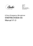
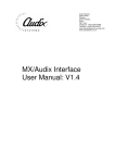
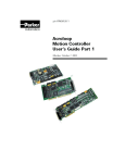
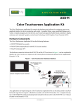
Audix Systems,
Station Road,
Wenden,
Saffron Walden,
Essex,
CB11 4LG.
Telephone: +44(0)1799 540888
Facsimile: +44(0)1799 541618
www.tycosafetyproducts-europe.com
www.audixsystems.co.uk
alpha
Configuration Suite V1.4
Manual
alpha Configuration Suite User Manual
Revision History
Issue
1.0
1.1
1.2
Modifications
Initial Draft
Initial Update
Update for Configuration Suite V1.4
Date
14/7/99
26/7/99
03/4/00
© Copyright Audix Systems. 2005
DISCLAIMER
This manual contains information that is correct to the best of Audix Systems knowledge. It is
intended to be a guide and should be used as such. It should not be considered as a sole
source of technical instruction, replacing good technical judgement, since all possible
situations cannot be anticipated. If there are any doubts as to exact installation, configuration
and/or use, call Audix Systems at +44 (0)1799 540888
ACKNOWLEDGEMENTS
Windows™, Windows 95™ and Windows 98™ are trademarks of Microsoft
Corporation
All other trademarks are recognised
Page 2 of 33
21003-1.2
alpha Configuration Suite User Manual
Technical Support
In the unlikely event of you having problems with the alpha configuration suite please contact
our Customer Services Department.
Audix Systems
Station Road
Wenden
Saffron Walden
CB11 4LG
Tel 01799 540888
Fax 01799 541618
Website www.tycosafetyproducts-europe.com
Page 3 of 33
21003-1.2
alpha Configuration Suite User Manual
REVISION HISTORY..................................................................................................................2
TECHNICAL SUPPORT ............................................................................................................3
ALPHA CONFIGURATIONS USING A PC.........................................................................................5
Installing the alpha configuration suite ................................................................................5
Running the alpha configuration suite. ................................................................................5
SYSTEM PROTECTION................................................................................................................6
FILE MENU ................................................................................................................................9
EDIT MENU .............................................................................................................................10
EDIT SIU ................................................................................................................................11
EDIT BUTTON ..........................................................................................................................12
EDIT MATRIX ...........................................................................................................................13
EDIT PIO (PARALLEL INPUT/OUTPUT).......................................................................................14
EDIT BUSY ..............................................................................................................................15
EDIT LIVE ................................................................................................................................16
EDIT SURVEY ..........................................................................................................................17
EDIT VOLUME (CONFIGURE INPUT LEVELS)...............................................................................18
EDIT TRIGGER (CONFIGURE TRIGGER) .....................................................................................19
PASSWORD .............................................................................................................................20
CONFIGURE MENU (NOW HAS TRIGGER & INPUT LEVEL) ...........................................................21
CONFIGURE SIU......................................................................................................................22
Example 1..........................................................................................................................22
Example 2..........................................................................................................................23
CONFIGURE PTT ....................................................................................................................23
CONFIGURE PTT.....................................................................................................................24
CONFIGURE MESSAGE .............................................................................................................25
CONFIGURE LOCK TIME ...........................................................................................................25
CONFIGURE COMMUNICATIONS ................................................................................................26
VIEW MENU (INACTIVE)............................................................................................................26
VIEW STATISTICS (INACTIVE)....................................................................................................27
SIMULATE MENU (INACTIVE).....................................................................................................28
SIMULATE SIU (INACTIVE)........................................................................................................28
SIMULATE PTT (INACTIVE) .......................................................................................................29
HELP MENU ............................................................................................................................30
ABOUT ....................................................................................................................................30
INSTRUCTION DEFINITIONS.......................................................................................................31
SIU.....................................................................................................................................31
INPUT Definition................................................................................................................31
SIU Definition.....................................................................................................................31
Input Definition...................................................................................................................31
PMCV Push Button Definition ...........................................................................................32
Input Source Definition ......................................................................................................32
Output Zone Definition ......................................................................................................32
Matrix Definition.................................................................................................................32
Trigger Definition ...............................................................................................................32
Parallel I/O Definition.........................................................................................................32
Busy Definition...................................................................................................................33
Live Definition ....................................................................................................................33
Wakeup Definition .............................................................................................................33
Surveillance Definition.......................................................................................................33
Message Configuration .....................................................................................................33
Page 4 of 33
21003-1.2
alpha Configuration Suite User Manual
alpha Configurations using a PC
The alpha is configured by a simple ASCII text file. This file can be downloaded to the alpha
and uploaded to the configuration PC for analysis and modifications.
When configuring the alpha using the Windows alpha configuration suite, the generation of
the ASCII text file is done for you. The configuration suite also checks the configurations for
errors. It is possible to edit the file using a simple text editor such as notepad, but caution
should be taken as the configuration will not be checked for errors, and this could cause the
alpha to not operate as desired.
Installing the alpha configuration suite
The alpha configuration suite is designed to operate in a Microsoft Windows 95/98
environment.
Insert the installation disk. Select “Run” on the “Start Menu”
Within the box type a:\setup.exe, then Click on the “Ok” box.
Follow the menus on screen to complete installation.
Running the alpha configuration suite.
Click on the alpha configuration suite Icon to start the program.
Page 5 of 33
21003-1.2
alpha Configuration Suite User Manual
System Protection
Before you can use the alpha configuration suite you must input your Username and
Password then press OK. The passwords are common for both the software suite and user
access from the front panel of the alpha.
The Configuration PC will now try to communicate with the alpha
If it fails to connect with the alpha you will get the following display.
The Configuration Suite can be used Off-line, This enable configurations to be produced and
edited off-site before downloading to the alpha.
Before you can use the Configuration suite you will need to either open an existing
configuration, create a new one or up-load the configuration resident in the alpha.
To open an existing configuration, simply select File-Open and select from the list of
configurations the file required.
The alpha configuration suite automatically checks the configuration for errors when loading.
If the configuration is Ok you will get the following message.
Page 6 of 33
21003-1.2
alpha Configuration Suite User Manual
If the configuration has errors you will see the following box appear. Click on the OK button
to check the errors in the configuration.
Page 7 of 33
21003-1.2
alpha Configuration Suite User Manual
The Configuration File Editor shows the ASCII text file that has been generated by the
configuration. The file can simply be edited here.
Fix the errors and press OK. If there are still errors the error box will shown again stating the
amount of errors. Re edit the file again until
Clicking on the Error File Tab shows all of the error currently in the configuration, It gives the
problem and line in the configuration that contains the error.
Page 8 of 33
21003-1.2
alpha Configuration Suite User Manual
File Menu
New
Open
Send
Receive
Load Backup
Save
Save As…
System Lock
Exit
Selecting this will generate a new configuration
Selecting this will open an existing configuration
This will transfer the current open configuration from the PC to the alpha via the
serial link
This will upload the current configuration operating within the alpha to the PC via
the serial link for viewing and editing in the configuration suite.
The configuration suite automatically saves a backup of each configuration. If
necessary you can load this backup to reverse any changes to the open
configuration.
Save the current open configuration
Saves the current configuration under a different name
Enables the system lock, preventing unauthorized users from editing the open
configuration. Simply re-enter your user password to continue editing.
Exit from the alpha configuration Suite
Page 9 of 33
21003-1.2
alpha Configuration Suite User Manual
Edit Menu
S.I.U
Button
Matrix
PIO
Busy
Live
Wake
Survey
Macro
Volume (now in Configure Menu “Input Level”)
Trigger (now in Configure Menu)
Password
Add or Edit A Serial Interface Unit
Edit a Button on an SIU
Configure Inputs and Outputs to the Matrix
Configure Parallel I/O
Configure Busy Outputs
Configure Live Outputs
Configure Wake up Signaling to amplifiers
Set up 20kHz Critical path testing signal
sources.
Not yet implemented
Volume and EQ settings for each input to the
matrix
Configure SIU buttons to trigger an I/O line
Configure User Passwords
Page 10 of 33
21003-1.2
alpha Configuration Suite User Manual
Edit SIU
SIU Name
SIU ID
Report Faults
Retry Attempts
Response Time
Failed Poll Rate
Normal Poll Rate
Normal Poll Rate
ProtoCol
Button Qty
Each mic unit can be given a unit name.
Each Mic unit must have a unique ID.
The mic unit can be configured to report any communications faults to the
FMS system.
Sets the amount of communications retries to a failed mic unit.
Set the time limit that the alpha waits for a reply from a polled mic unit
Sets the frequency at which the mic unit is attempted to be polled by the
alpha after a comms failed
Sets the frequency at which the alpha communicates with the mic unit
Sets the frequency at which the alpha communicates with the mic unit
Leave Set to 0
Unused
To Create a new SIU Press the New SIU button and configure as required.
If you need to add an SIU and it is similar to an existing SIU, using the Copy SIU may be
quicker to configure.
Press Apply to make the changes, and Ok to accept the Changes
To Delete the properties press delete, and then Ok to accept the Changes
To Ignore the changes press Cancel
For Help press Help.
Page 11 of 33
21003-1.2
alpha Configuration Suite User Manual
Edit Button
SIU Name
Button Name
Button ID
Button Override
Button Priority
Select the SIU of which you wish to edit the button configuration
Selects The button you wish to configure
Indicated the ID number of the selected button
Select for the button to be overriden by either another zone or another button
Each button can be configured to have its own priority.
Press Apply to make the changes, and Ok to accept the Changes
To Delete the properties press delete, and then Ok to accept the Changes
To Ignore the changes press Cancel
For Help press Help.
Page 12 of 33
21003-1.2
alpha Configuration Suite User Manual
Edit Matrix
Matrix Name
Matrix ID
Port Name
Port ID
Type
Busy Threshold
This allows you to name each of you matrices
Indicates the unique ID number
Each Input and Output can be given a unique
name.
This will indicate the physical ID of each input
or output
Select Input or Output to switch between I/O
types
Sets the threshold at which the input or output
will give a Busy output indication
Press Update to make the changes, and Ok to accept the Changes
To Delete the properties press delete, and then Ok to accept the Changes
To Ignore the changes press Cancel
For Help press Help.
Page 13 of 33
21003-1.2
alpha Configuration Suite User Manual
Edit PIO (Parallel Input/Output)
PIO Port
Port
8-1
Select either 1 or 2 for first or second bank of
8 I/O points.
Selects IO type you wish to edit (input or
Output)
Enable you to select the status of any input or
output to be Active Hi or Active Low
Press Apply to make the changes, and Ok to accept the Changes
To Delete the properties press delete, and then Ok to accept the Changes
To Ignore the changes press Cancel
Page 14 of 33
21003-1.2
alpha Configuration Suite User Manual
Edit Busy
Busy
Destination Name
Destination Button
IO Pin Number
Priority
Name of the Busy control signal
Matrix Name
Selects a button you require to generate a busy
output
Selects the Output you wish to trigger as a
result of a busy being generated
Sets the priority of the busy output
Press Apply to make the changes, and Ok to accept the Changes
To Delete the properties press delete, and then Ok to accept the Changes
To Ignore the changes press Cancel
Page 15 of 33
21003-1.2
alpha Configuration Suite User Manual
Edit Live
Live
Source
IO Pin
Give each Live output used a unique name.
Select the input, which will generate the Live
output. State matrix number and audio source
within that matrix.
Select I/O pin to operate for the Live output.
Press Apply to make the changes, and Ok to accept the Changes
To Delete the properties press delete, and then Ok to accept the Changes
To Ignore the changes press Cancel
Page 16 of 33
21003-1.2
alpha Configuration Suite User Manual
Edit Survey
Wake Name
Survey Source
Survey Zone
Name of the Wake Up signal to operate before
the broadcasting the 20kHz surveillance tone.
Select the source unit that will generate the
surveillance tone.
Add the zones the surveillance is required to
cover.
Press Apply to make the changes, and Ok to accept the Changes
To Delete the properties press delete, and then Ok to accept the Changes
To Ignore the changes press Cancel
For Help press Help.
Page 17 of 33
21003-1.2
alpha Configuration Suite User Manual
Edit Volume (Configure Input Levels)
Source
Controls
Selects the audio source input to modify
Set the individual Volume and EQ levels of the selected audio input
To accept the changes you have make press
To ignore the changes press Cancel
Page 18 of 33
21003-1.2
alpha Configuration Suite User Manual
Edit Trigger (Configure Trigger)
SIU Name
Button
IO Information
Select the SIU that will generate the trigger
Select the button which will cause the trigger
Select the I/O pin you wish to be triggered, you
need to state port number and pin
Press Apply to make the changes, and Ok to accept the Changes
To Ignore the changes press Cancel
For Help press Help.
Page 19 of 33
21003-1.2
alpha Configuration Suite User Manual
Password
Password
Access Level
Input a Password
Select the level of Access. Passer-by, User,
Engineer or Superuser.
Press Add to add a user, Press Finish to accept the Changes
Press Delete to remove a user, and then Finish to accept the Changes
Page 20 of 33
21003-1.2
alpha Configuration Suite User Manual
Configure Menu (Now has Trigger & Input Level)
S.I.U
Ptt
Message
Lock Time
Comms
Configure the Serial Interface Unit’s
Assignments
Configure Ptt’s inputs to the alpha
Configure the message cards of the alpha
Adjust the settings of the screen lock.
Configure the Comms settings of the
configuration PC
Page 21 of 33
21003-1.2
alpha Configuration Suite User Manual
Configure SIU
Example 1
This example shows the Routing of a microphone Audio Source to its Destination, dependant
upon a button selection on a specific SIU. Shown below is how the above configuration
would work in practice.
Page 22 of 33
21003-1.2
alpha Configuration Suite User Manual
Example 2
This example shows the Routing of a message as the audio source to multiple destinations
dependant upon a button selection on a specific SIU. Shown below is how the above
configuration would work in practice
Page 23 of 33
21003-1.2
alpha Configuration Suite User Manual
Configure PTT
PTT Name
Input Pin Number
Source
Destination
Priority
OverRide
Name of PTT signals
Set up the input pin that will be used for the
PTT signal.
Source input you wish to route
Destination you require your source input to be
routed to.
Sets the priority of the PTT signal
Configures the PTT to be either overriden by
another button or a complete Zone.
This Setup screen is used primarily to configure the operation of the SMU 1 microphones.
This pre configures the source and destination routing for when the PTT button is pressed.
The PTT is not limited to this, it could also be configured to accept any closing or opening
contact e.g. from a fire panel and route a source, e.g. an Evacuation message to a
destination.
Press Update to make the changes, and Ok to accept the Changes
To Delete the properties press delete, and then Ok to accept the Changes
To Ignore the changes press Cancel
For Help press Help.
Page 24 of 33
21003-1.2
alpha Configuration Suite User Manual
Configure Message
Message Source
Message Name
Message Id
Segment
Silence
Playback type
Level Controls
Select the source message card 1,2, or 3
You can give each message a informative
name
Each message has a unique Id, shown here.
Each D776 Message card is split into 10
segments. Select here the segment in which
the message is held.
Allows you to configure a fixed length of silence
after a message.
Each message has the option of either playing
the whole message to the end when the button
has been pressed and released or only playing
the message while the button is held
The sliders provide Volume and EQ controls on
a per message biases. There is also a volume
control for the 20kHz surveillance tone.
Press Apply to make the changes, and Ok to accept the Changes
To Delete the properties press delete, and then Ok to accept the Changes
To Ignore the changes press Cancel
For Help press Help.
Configure Lock Time
Page 25 of 33
21003-1.2
alpha Configuration Suite User Manual
Enter a Time for the Screen lock to activate, to prevent unauthorized users from using the
configuration software.
Configure Communications
Port Settings
Select the communications Port of the
Configuration PC you wish to use to
communicate to the alpha
Poll
Frequency at which the alpha is sent
messages (polled)
Configure the amount of time the PC will retry
the communications before failing the link.
Time to wait for a response back from the
alpha after proccess a packet
Reset defaults
Retry
Data Packet
Default
To keep any changes press Apply.
To discard the changes press cancel
View Menu (Inactive)
Page 26 of 33
21003-1.2
alpha Configuration Suite User Manual
Map
Statistics
Not yet implemented
Shows the real time statistics of the alpha
connected to the configuration PC
View Statistics (Inactive)
Page 27 of 33
21003-1.2
alpha Configuration Suite User Manual
Simulate Menu (Inactive)
S.I.U
Ptt
Macro
Simulate a Serial Interface Unit
Simulate the PTT control
Not Yet Implemented
Simulate SIU (Inactive)
Note: For this function to operate the Configuration PC must be connected to the alpha via
the serial link.
This allows you to simulate the operation of any of the SIU’s configured on the alpha. This
enable you perform full system testing without having to wire up all the SIU’s.
Page 28 of 33
21003-1.2
alpha Configuration Suite User Manual
Simulate PTT (Inactive)
Note: For this function to operate the Configuration PC must be connected to the alpha via
the serial link.
This allows you to simulate the operation of any of the PTT input configured on the alpha.
This enable you perform full system testing without having to wire up all the PTT inputs.
Page 29 of 33
21003-1.2
alpha Configuration Suite User Manual
Help Menu
Contents
Using Help
About…
Unavialable
Unavialable
Shows version and issue of configuration
software
About
Page 30 of 33
21003-1.2
alpha Configuration Suite User Manual
Instruction Definitions
SIU
#SIU,a,b,c,d,e,f,g,h,i;
a – SIU Number (1 to 8)
b – Button Number (1 to 16)
c – Source Matrix (1)
d – Source Port (1 –16)
e – Destination Matrix (0 or 1)
f – Destination Port (0 to 16)
g – Button Priority (1 to 255)
h – Override (Zone or Button)
i – Message Id Number (0 to 30)
Note:
If the destination port is set to zero, then the button has been configured to select a message.
Other buttons can be configured on the same SIU to route this selected message to the
different destination zones.
INPUT Definition
#INPUT,a,b,c,d,e,f,g,h,i,j;
a – Input Number (1 to 16)
b – Input Port Number (3 or 4)
c – Input Bit Number (1 to 8)
d – Source Matrix (1)
e – Source Port (1 to 16)
f – Destination Matrix (0 or 1)
g – Destination Port (1 to 16)
h – Priority (0 to 255)
i – Override (Zone or Button)
j – Message Id Number (0 to 30)
SIU Definition
#SIUDEF,a,b,c,d,e,f,g;
a – SIU Name
b – SIU Number (1 to 8)
c – SIU Fault Reporting (Fault Reporting On = 1, Fault Reporting Off = 0)
d – SIU Communications Retries (1 to 16)
e – SIU Communications Response Timeout (1 to 1000)msec
f - SIU Fail Poll Rate (1000 to 3000)msec
g - SIU Normal Poll Rate (1 to 1000)msec
Input Definition
#INPUTDEF,a,b;
a – Input Name
b – Input Number (1 to 16)
Page 31 of 33
21003-1.2
alpha Configuration Suite User Manual
PMCV Push Button Definition
#BUTTONDEF,a,b,c,d,e;
a – Button Name
b – Button Number (1 to 16)
c – SIU Number (1 to 8)
d – Button Priority (0 to 255)
e – Override (Zone or Button)
Input Source Definition
#SOURCEDEF,a,b,c,d,e,f;
a - Input source type (Message Card or Source)
b – Matrix Number (1)
c – Input Port Number (1 to 16)
d – Input Volume Level (0 to 63)
e - Input Bass EQ Level (0 to 63)
f – Input Treble EQ Level (0 to 63)
The user selects must select the type of input either message card or source (typically a
PMCV). The matrix number relates to the network address of the alpha. The input port
number is the port the input is physically connected to. Each source can also be configured
with individual Volume and EQ settings.
Output Zone Definition
#ZONEDEF,a,b,c;
a – Zone Name
b – Matrix Number (1)
c – Audio Output Channel Number (1 to 16)
Matrix Definition
#MATRIXDEF,a,b,c;
a – Matrix Name
b – Matrix Reference Number (1)
c - Busy Threshold (1 to 255)
Trigger Definition
#TRIGGER,a,b,c,d;
a – I/O Port Number (1 to 4)
b – I/O Pin Number (1 to 8)
c – SIU Number (1 to 16)
d – Button Number (1 to 96)
Parallel I/O Definition
#PIO,a,b,c;
a – I/O Pin Number (1 to 4)
b – Select I/O type (Input or Output)
c – Selects Active High or Active Low Output. Bit Clear for Active High, Bit Set for Active
Low.
Page 32 of 33
21003-1.2
alpha Configuration Suite User Manual
Busy Definition
#BUSY,a,b,c,d,e,f;
a – Busy Signal Name
b – Busy Port Number (1 or 2)
c – Busy Bit Number (1 to 8)
d – Matrix Number (1)
e – Destination Port Number(1 to 16)
f – Busy Priority (0 – 255)
Live Definition
#LIVE,a,b,c,d,e;
a – Live Signal Name
b – Live Port Number (1 or 2)
c – Live Bit Number (1 to 8)
d – Matrix Number (1)
e – Source Port Number (1 to 16)
Wakeup Definition
#WAKE,a,b,c,d;
a - Wakeup Signal Name
b - Wakeup Id Number (1 to 16)
c - Wakeup Port Number (1 or 2)
d – Wakeup Bit Number (1 to 8)
Surveillance Definition
#SURVEY,a,b,c,d,e;
a – Wakeup Id Number (1 to 16)
b – Source Matrix (1)
c – Source Port (1 to 16)
d – Destination Matrix (1)
e – Destination Port (1 to 16)
Message Configuration
#MSGCFG,a,b,c,d,e,f,g,h,i,j,k;
a – Message Name
b – Message Id Number (0 to 30)
c – Source Matrix (1)
d – Source Port (1 to 16)
e – Message Segment Number (0 to 9)
f – Message Volume Level (0 to 63)
g - Message Bass EQ Level (0 to 63)
h – Message Treble EQ Level (0 to 63)
I – Surveillance Level (0 to 9)
j – Silence after end of Message (0 to 9) seconds
k – Mode, Message can be configured for ‘Play To End’( ) or ‘Play While Held’ ( )
Each message can be assigned a name, this is ignored by the alpha,
Page 33 of 33
21003-1.2