1
HARDING UNIVERSITY
Single Player Against
Machine BAttleship Game
Mid-Term Progress Report
Matt Goodhart
Timothy Hoffmann
Matt Lewis
March 3, 2010
Tatiana Zeledon
Table of Contents
Requirements Specification ...................................................................................................... 4
Project Overview and Status .................................................................................................... 8
Accomplishments ...................................................................................................................... 9
LCD Screen .................................................................................................................. 10
Microcontroller ............................................................................................................ 11
Test Code ..................................................................................................................... 11
Power Supply ............................................................................................................... 14
LED Display and Digital Logic ................................................................................... 14
Keypad ......................................................................................................................... 18
Electromagnet .............................................................................................................. 19
Frame Construction .................................................................................................... 20
Motors .......................................................................................................................... 22
Steel Ball Bearings ....................................................................................................... 24
Ship Sensor Design ...................................................................................................... 25
Gears ........................................................................................................................... 30
Racks ............................................................................................................................ 31
Budget Analysis ....................................................................................................................... 40
Schedule Analysis .................................................................................................................... 41
Gameplay Flowcharts ............................................................................................. Appendix A
Gameplay Code ....................................................................................................... Appendix B
CNC Code................................................................................................................ Appendix C
Alternate Gear and Rack Calculations .................................................................. Appendix D
S-R Latch Data Sheets ............................................................................................ Appendix E
NAND Gate Data Sheets ......................................................................................... Appendix F
Power Rectifier Data Sheets ................................................................................... Appendix G
Multiplexer Data Sheets .......................................................................................... Appendix H
LED Data Sheet ........................................................................................................ Appendix I
Push Button for Keypad Data Sheet........................................................................ Appendix J
LCD Data Sheets ..................................................................................................... Appendix K
Microcontroller Data Sheets ................................................................................... Appendix L
Voltage Regulator Data Sheets .............................................................................. Appendix M
Electrolytic Capacitor Data Sheet .......................................................................... Appendix N
Resistor Data Sheet ................................................................................................. Appendix O
2
Electromagnet Data Sheet....................................................................................... Appendix P
Transformer Data Sheet ......................................................................................... Appendix Q
Encoder Data Sheets ............................................................................................... Appendix R
Power MOSFET Data Sheets.................................................................................. Appendix S
Plexiglas Data Sheet ................................................................................................ Appendix T
Stepper Motor Data Sheets ..................................................................................... Appendix U
Steel Ball Data Sheet ............................................................................................... Appendix V
Push Button for Ship Sensor Data Sheet ............................................................... Appendix W
Delrin Data Sheets ................................................................................................... Appendix X
English Gear Data Sheet ......................................................................................... Appendix Y
Metric Gear Data Sheet .......................................................................................... Appendix Z
Metric Gear Rack Data Sheet .............................................................................. Appendix AA
3
Single Player Against Machine BAttleship Game
(SPAMBAG)
Requirements Specification
Matt Goodhart, Timothy Hoffmann, Matt Lewis, Tatiana Zeledon
OVERVIEW:
Battleship is a classic game that many people play in their childhood. Typically,
it is a two player game where one person plays against another. We are recreating this game so
that one person can play by themselves against an interactive computer that has a robotic piece
placement device. This allows a novice player to get a feel for the rules and potentially develop
and improve strategies of their own. Aside from the inputs from the player on where he/she
wants to place his/her ships and target the computer’s ships, the game is hands free.
OPERATIONAL DESCRIPTION:
Our battleship game will follow all of the standard rules of the classic battleship game.
There will be a user input-interface, most likely an interactive LCD screen that will prompt the
user with instructions and notifications, such as when to make a move or indicate when the
player sunk one of the computer’s ships. There will also be a keypad which will accept the
coordinates of the player’s moves. Beginning game play will require the player to physically
place his/her ship pieces on the lower display. Once the player’s ships have been placed, the
game begins a random selection of who (player or computer) goes first. This selection will be
indicated on the LCD screen. On his/her turn, the player inputs his/her move. The
microprocessor then discerns if the input was a hit or miss and gives the corresponding output on
the upper display. Outputs include lighting a red LED (hit) or a green LED (miss). On the
computer’s turn, it makes a move, the microprocessor discerns a hit or miss, and shows its output
on the lower display by placing a red (hit) or green (miss) ball via the ball manipulator into its
respective spot. This process is repeated until the game is over.
DELIVERABLES:
· User’s Manual
· Software Logic Flowchart
· Technical Drawings and Analysis of Hardware
· Schematic of Circuit with Simulation Results
· Documentation of Testing
· A Final Report
· Parts List with Budget
· Battleship Game
4
DRAFT USER MANUAL:
Setup:
·
·
·
·
·
Remove the game from its package
Open the lid for the game
Plug in the power cord to a Type B NEMA 5-15 15 A/125 V grounded outlet.
Separate the balls by color and load them into the containers.
Turn on the game by flipping the ON/OFF switch located on the board.
Operation:
1. Physically place the ship pieces on the lower display board so that the holes in the
piece correspond to holes in the board.
· For the aircraft carrier (five cells).
· For the battleship (four cells).
· For the cruiser (three cells).
· For the submarine (three cells).
· For the destroyer (two cells).
2. Wait for the computer to choose the location of its ships as indicated by the LCD
screen located in the upper display of the game.
3. If the LCD screen indicates that it is the player’s turn, select coordinate of attack (a
space on the grid you believe the computer’s ship is). If the LCD screen indicates that
it is the computer’s turn, continue to step six (beginning of game only).
4. Enter the coordinate on the keypad by selecting the letter (A-J) that corresponds to the
chosen location and then select a number (1-10) that corresponds to the same
location.
5. Notice the LED light up which indicates that the coordinate selected in step 3 was
either a hit (red) or a miss (green).
6. Wait for the computer’s turn.
7. The attack of the computer will be recorded by dropping a ball on the lower display.
The ball will be red if it coincides with the location of one of your ships; it will be
green if it is a miss.
8. Repeat steps three through seven until the game is completed as indicated by the LCD
screen.
9. Select the option to play a new game if desired and repeat steps one through eight or
turn off the device using the ON/OFF switch on the lower display.
10. Unplug the game from the outlet.
5
USER INTERFACE:
The user interface will consist of an ON/OFF switch that allows the system to be turned
on and off. There will also be ship pieces for the user to physically place on the lower display
board to indicate the location of the user’s ships. There will be a keypad that will act as an input
receiver for the user’s moves and will also have keys for the player to indicate if the computer
sunk a ship. Also included is an interactive LCD screen that will prompt the user when it is their
turn, whether they hit or missed the computer’s ship, and other instructions throughout the
gameplay.
CAPABILITIES:
· Will have artificial intelligence for the computer to choose locations close to a hit in
order to sink the user’s ship. Once two hits are found, only locations along a straight
line should be attempted until a sinking takes place as confirmed by the user via the
keypad. When the user indicates which ship has been sunk via the keypad, the
computer will determine if it hit another ship in the process. If so, the computer will
continue selecting coordinates in the area until it sinks that ship. Once the computer
determines that there are no more known ships in the area, it will continue selecting
random coordinates of attack.
· Will be able to be operated and moved by one person.
· Will acknowledge whether the coordinate selected corresponds to either a hit or a
miss by displaying a message in the LCD screen and lighting up the LED in the upper
display of the game that corresponds to the coordinate selected by the user. If it is a
hit the color of the LED will be red and if it is a miss it will be green.
· Will be able to setup in no more than 5 minutes.
· Will be able to place balls of different colors to different locations on the board in no
more than 20 seconds per move.
TESTING:
Ball Manipulator Test / Motor Test: To test the ball manipulator and the motors, a full
mechanical system test will be performed where a test program is run and tells the ball
manipulator to place one ball in every possible location (A1-A10 though J1-J10) in order. The
test will be considered successful if the mechanical device arrives at the correct coordinate every
time and if the ball makes it to the coordinate without dropping prematurely 99 out of 100 times
the movement is done. This test will be run five times and statistical analysis will be performed
on the results. If the ball drops prematurely, the user can place the ball in the correct location as
displayed on the LCD screen.
6
Portability Test: To determine portability and ease of operation by one person, three
volunteers not associated with the Senior Design class will move the device to a testing room
where outlets are available and will follow the setup and operation as described in the user’s
manual. Feedback will be gathered from the volunteers via a survey to determine if the device is
portable and through observation if it is easily operated. The game will weigh no more than
22.73 kg (50 pounds) and will take up a volume no more than 1.0 m3. The footprint of the
device will be no more than 1.0 m2 and its depth no greater than 1.0 m.
LEDs Test: To test the proper functioning of the LEDs, the program will be written so
that every possible location corresponds to a hit. Then, a tester will key in values for all one
hundred locations. The program will reset the board and repeat the process so that all locations
correspond to a miss. Only one LED must be lit whenever a coordinate is entered and should be
either green (miss) or red (hit). If only one LED lights up for each entry and corresponds to the
correct color, the LED test will be considered a success. Also, there will be a question on the
survey for the volunteers that asks how easily the LEDs were seen.
Artificial Intelligence Test: To test the artificial intelligence of the computer, following
a hit, it must continue choosing coordinates in the immediate proximity of the hit. Once two hits
are found, only locations along a straight line should be attempted until a confirmed sinking
takes place. Also, if it is known that a particular ship has been sunk, the computer will not
attempt to re-sink that battleship. Once sunk, the computer may choose a random location of
attack based on an externally programmed algorithm. The AI will be tested by playing the game.
7
Project Overview and Status
Our goal is to create an essentially hands-free version of the classic Battleship® game.
The game will be powered through a standard 110 VAC household outlet. There will be a
keypad that will receive input such as accepting the coordinates of the player’s moves. Also,
there will be an LCD screen that will provide feedback to the user and will prompt the user with
instructions and notifications, such as when to make a move or indicate when the player has sunk
one of the computer’s ships.
The major accomplishments that have been reached this semester include the cutting of
all Plexiglas pieces, the construction of the motor carts, the boring out of the gears to ensure that
they can be securely attached onto the stepper motors’ shafts, bread-boarding of the power
circuitry, learning to use the software for CNC programming, the modification of the design of
the power circuit, and the learning of the implementation for the programmer and the
microcontroller.
Though we have reached many of our goals on time, we are making less progress than
anticipated. This time delay is due to the change of some modules of the project to ensure the
creation of a prototype that meets our requirements specification. Because the ship sensor
module and LED module have changed significantly and the original spring schedule was done
with a lack of knowledge of the remaining tasks to be completed, an updated schedule for the
spring semester has been developed. This new schedule includes much more detail of the
specific parts of each module that need to be completed. This will allow us to continue with the
building and testing phases and complete the integration of the individual modules of our project
on time. The fabrication of the gear racks, uploading of working code into the microcontroller,
and PCB design of the LED array and digital logic have been our biggest roadblocks. These
roadblocks were caused mainly by the lack of knowledge of the CNC programming language
and functioning of the microcontroller and programmer and the complexity of the digital logic.
The difficulty of the programming and the uploading of the code were underestimated. On the
other hand, we have been able to make good progress on areas such as: sensing system, gears,
LCD screen and construction of the frame. The changes and current status of our project will be
discussed in detail in this report.
As we continue in the assembling and testing phases of our project, there are still some
changes that will need to be made for our Battleship game to operate in the way it is intended.
These areas will most likely be in the frame measurements, attachment of the sensing system
onto the overall movement system and the PCB layouts. Over the next few weeks, the gear racks
will be fabricated, frame assembly will be complete, and the code will be uploaded into the
microcontroller. These accomplishments will enable us to continue with the assembling and
testing of the independent modules for them to be integrated into the overall project.
8
Accomplishments
9
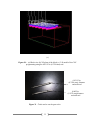
LCD Screen
The LCD screen has sixteen wires that send power and signals that run the screen
according to the specifications sent from the manufacture. While soldering wires to the circuit
board for our LCD screen, one of the solder pads was damaged causing complications in
operation during testing. After finding the issue with the damaged solder pad, it was able to be
repaired after a difficult process to fix the problem. The working LCD screen is shown in Fig. 1
outputting test values from the program written on our dsPIC30F6015 microcontroller.
Figure 1 – LCD output
In Fig. 2 below, you can see the leads more closely, including the one that was damaged.
The pad in the lower right hand corner of Fig. 2 was the one that was damaged. You can see how
the wire had to be bent over to the trace in order to solder a connection. Using a microscope and
a high quality soldering iron, the precise connection needed for the repair was made.
Figure 2 – Solder pads
The datasheet and other information for the LCD screen used in this project can be found
in Appendix K.
10
Microcontroller
In this project, we went with the dsPIC30F6015 microcontroller from Microchip due the
convenience of equipment provided by the school and because of the optimal amount of
input/output pins for the project’s needs. As of right now, we are writing functions for the LCD
screen and stepper motors. We have been able to test these devices and they work well. The
code that has been written that should print to the LCD and then run the stepper motor
continuously can be found in Appendix B.
Figure 3 – MPLAB PM3
The code used to test the microcontroller initially looked like the code below that flashed
an LED. The code below did not work however; this was likely due to two possible issues. The
first issue with this code was the possibility that the I/O pins were not responding, meaning they
were not initialized correctly. The other issue was that the microcontroller was corrupted due to
electrostatic damage. These microcontrollers are very sensitive, and since the issue seemed to be
the electrostatic damage, additional microcontrollers were ordered so that we have nine.
Modifications have been made to how the code is set up and those modifications can be viewed
in the test code included in Appendix B.
Test Code
#include <p30f6015.h>
// Config directive to set configuration bits
_FOSC(CSW_FSCM_OFF & XT_PLL4);
_FWDT(WDT_OFF);
_FBORPOR(PBOR_ON & BORV_20 & PWRT_64 & MCLR_EN);
#define FCY 7378200
#define MILLISEC FCY/7378
// 7.37Mhz crystal in 4X PLL mode
// 1 mSec delay constant
11
#define
#define
#define
#define
LED1
LED2
LED3
LED4
PORTDbits.RD4
PORTDbits.RD5
PORTDbits.RD6
PORTDbits.RD7
// LED connected to RD4
// LED connected to RD5
// LED connected to RD6
// LED connected to RD7
// Definitions for subroutines
void SetupPorts(void);
void DelayNmSec(unsigned int N);
void DelayMSec(unsigned int N);
int main(void)
{
SetupPorts();
while(1)
{
LED2 = !LED2;
DelayNmSec(200);
}
}
void SetupPorts(void)
{
PORTD = 0;
TRISD = 0xFF0F;
}
// Initialize I/O
// Do endlessly
// sample keys every 20 mS
// end of while(1) statement
// end main
// Set RD7 to RD4 as outputs
void DelayNmSec(unsigned int N)
{
unsigned int j;
while(N--)
for(j=0;j < MILLISEC;j++)
{
DelayMSec(20);
}
}
void DelayMSec(unsigned int N)
{
unsigned int j;
while(N--)
for(j=0;j < MILLISEC;j++);
}
12
After writing working code to the microcontroller, we were able to test it using the TQFP
to DIP adapter pictured in Fig. 4 below that was provided by the school. You can also see how
the circuit is set up to test the LCD screen and the stepper motor simultaneously. This adapter
will be used for testing until the final code has been written to the microcontroller and testing is
done. In addition, we are using an NI ELVIS station for power until we have a working power
system for the project.
Figure 4 - MCU test circuit
Most of the code will come from the flowcharts which can be viewed in Appendix A
(flowcharts) and Appendix B (code). Once all testing of the code is completed and the final
version of the code has been loaded to the microcontroller, it will then be attached to a Schmart
board. Pictured below in Fig. 5 is the type of Schmart board that will be used in our project. The
advantage of this product is that it is an EZ solder product. The solder is already on the board
where the leads from the microcontroller make contact, which is optimal for components this
small.
Figure 5 – Schmart Board
The datasheet and other information for the microcontroller used in this project can be
found in Appendix L.
13
Power Supply
The power supply circuit has been modified slightly from its original design. This
modification was due to the previous design’s inability to produce a sufficient amount of current
to the LED module. In the original design, the power supply was using a series of resistors as a
voltage divider but this did not account for the current sinked. Hence, the modification made was
the addition of an op-amp as a voltage follower after the needed voltage has been reached by the
voltage divider circuit. This op-amp references the voltage outputted from the original design
and outputs an equivalent voltage, but the current is drawn through the +Vcc.
Figure 6 – Voltage Follower Circuit
This eliminates the limit that the original design put on the current drawn from the power
supply. The voltage follower is the only major change that has been made to the power supply’s
design.
LED Display and Digital Logic
Similar to the power supply, the LED array has not changed much either. It is still a ten
by ten grid of dual color, lead dependent LEDs which accept signals from the digital logic
module. The digital logic module has been changed slightly. The modification was necessary
because the outputs of the SR latches used are the complement of what was originally expected.
To explain, the Q output of the SR latch ‘keep state’ in Multisim happens when the inputs are
both low logic signals, but on the SR latch ordered, the ‘keep state’ happens when both logic
input signals are high. The original design was expecting the Q output of the SR latch to be ‘keep
state’ when the inputs were both low. The modification switch was made to expect the Q output
to be ‘keep state’ when both inputs are high. To explain furthermore, the difference in the logic
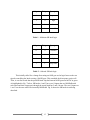
for an SR latch is shown in Table 1 and Table 2 below.
14
S input
R input
Q output
0
0
keep state
1
0
high
0
1
low
1
1
unstable
Table 1 – Multisim SR latch logic
S input
R input
Q output
0
0
unstable
1
0
low
0
1
high
1
1
keep state
Table 2 – Ordered SR latch logic
This initially called for a change from using an AND gate as the logic between the two
signals controlling the latch to using a NAND gate. This remedied the discrepancy quite well.
Then, it was discovered that the quad SR latch chip had internal AND gates on half of its gates.
As highlighted in Fig. 7 below, SR latches 1 and 3 have two S-inputs that are “ANDed” with
each other and their output goes through the actual latch but 2 and 4 do not. The two S-inputs on
1 and 3 are the ones which are internally “ANDed”. Fig. 8 shows the SR latch circuit being
described.
15
1S1
1S2
3S1
3S2
Figure 7 – SR latch Topview
Figure 8 – SR latch circuits
Originally, the AND on these two gates was an asset because it would save money that
would have been spent on the AND gates to be placed before it. But, since the design now
requires NAND gates instead of AND gates, it has saved nothing. This problem could not be
solved by inverting the output because the output was completely internal. In order to adapt to
this unforeseen problem, the new design will short the two inputs to those particular SR latches
and connect them to an output of an external NAND gate. This leaves these SR latches looking
very similar to the ones without the internal AND gate while still having the same functionality.
Fig. 9 below shows the design for the printed circuit board (PCB) without ground and
power. These two items will be added over the next day or two. The LED array is located
toward the center of the layout and the digital logic is located to the left, right and bottom of the
display.
16
Figure 9 – PCB Layout for LED Array and Digital Logic
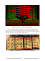
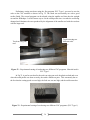
Fig. 10 below is a breadboard mockup of a 3x3 array of LED’s and the digital logic
running them. The LED’s are easily visible with ambient lighting but the camera was unable to
show the contrast of the color to the background well. Fig. 11 is of the same breadboard with the
room lights turned off to better display the lit LED’s in the photo.
Figure 10 – Breadboard mockup of a 3x3 LED array with digital logic
17
Figure 11 – 3x3 mockup with room lights turned off
Keypad
The keypad design is very straightforward. The original design uses an encoder to accept
signals from the keypad and reduces it to a smaller amount. In this project, we use the encoder to
encode the twelve decimal inputs to seven binary inputs. Now, instead of the maximum of
twelve pins it would have taken on the microcontroller, it will take only seven. The twelve pins
would have consisted of one pin for each button on the keypad but the encoder reduces eight of
those keys to only three and keeps the other four, making a total of seven.. Unfortunately, it
won’t be able to reduce all of the input lines to four like originally planned, but that’s only
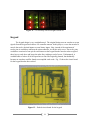
because no encoders could be found to accomplish such a task. Fig. 12 shows the circuit board
for the keypad that has been etched.
Figure 12 – Etched circuit board for the keypad
18
Fig. 13 below is a picture of the push buttons that will be used in the keypad. The circuit
board will be placed in the electronics holder on the right with leads running into the electronics
cover where the buttons will be attached. Twelve holes will be drilled into the cover and the
buttons can be fit inside of them and the top screwed back on top. If the cover or buttons should
ever need to be replaced, the buttons are easily removed by unscrewing the top and pulling the
button out of the hold.
Figure 13 – Push button for keypad
Electromagnet
The electromagnet has had no change in design and is currently awaiting implementation.
It still requires a fixture to attach to its head to allow it to interact with the balls better. Design
considerations for that include drilling a small indentation into the head to create a small divot
where the ball can rest or adding a small amount of solder to the head to create a ring where the
ball cannot roll around on the head. Fig. 14 shows the electromagnet used in this project.
Figure 14 – Electromagnet used in this project
19
Frame Construction
Little modification has been done to the design of the frame. One or two small pieces
have been removed from the motor carts because there was no good way to fasten them to the
rest of the cart. The removal does not affect any performance of the motor carts. After creating
the mock-up for the last report, the large size of the frame was apparent. Evidently, not all of the
space allotted for electronics will be needed, but it has been left alone in case modifications need
to be made later. The requirements specification states that the frame must stay within 1m x 1m
x 1m – which it has. The current dimensions are 28.25 inches (717.55 mm) wide by 24 inches
(609.6 mm) deep by 16 inches (406.4 mm) tall.
The Plexiglas pieces for the frame are all cut out of their original sheets. All of the pieces
are within 1/8 inches (3.175 mm) of their intended dimensions. All pieces small enough to fit
into the vice on the milling machine have been machined to their intended sizes within 0.005
inches (0.127 mm) neglecting surface roughness. Such pieces include the longitudinal and
latitudinal walls, the sides and top of the upper display, and the cross members. For larger pieces
such as the base, the plan is to make a very light impression or score in the surface of the
Plexiglas through the protective paper. It will not be enough to compromise the integrity of the
base; it is only to mark where the actual edge will be. The walls will be attached using the score
as a guide and after construction is complete, the overhang will be sanded off with very coarse
sandpaper followed by finer grit or very carefully using a Dremel sander. Fig. 15 shows the
completed motor carts without the stepper motors fixed to them so that the entire cart is visible.
Figure 15 – Completed motor carts
20
The hoppers have undergone a very major design change in the last week due to an
unforeseeable design flaw. Originally, when the hoppers were being designed, a switchback
system was created. This design was tested by building a 1:1 scale model of the hoppers using
cardboard because it was easy to use and obtain. The design worked well with the cardboard and
it was assumed that because the Plexiglas was much smoother than the cardboard that the balls
would roll even better. The hoppers were constructed and the design was tested. Unfortunately,
the balls did not move as they had in the cardboard tests; in fact, they did not move at all. We
believe this to be because there is a greater coefficient of static rolling friction between the
chrome steel balls and the Plexiglas than between the chrome steel balls and the cardboard. It
was only after the hopper was placed at about a 45° angle that they moved as originally expected.
Because of its size and the boundary conditions, this was not permissible, so an improved design
had to be created. Using the “miss” hopper as it had been constructed, it was cut in half and
made into a vertical hopper that will be glued to the front of the upper display on the lower righthand corner. The hopper itself will hold about 40 balls. A track that can hold an additional 4045 balls will come from the exit of the hopper that runs to the front of the frame over the top of
the electronics cover. It will make a 90° turn and the end of the track will be about where the
ball was to be picked up before. The trick with designing this is to ensure that the track does not
interfere with the path of the cart for the movement system. The “hit” balls will run along the
same track as the “miss” balls but separated by a thin divider. Because significantly less balls
are needed for the “hits”, no hopper is required; only the track. The assembled “miss” hopper
can be seen below in Fig. 16.
Figure 16 – Hopper for the “miss” balls
21
The method of fastening the frame together has changed slightly as well. Originally, the
pieces were going to be superglued to make sure they are in the right spot and then sealed with
silicone. After testing the strength of the superglue and the silicone, we have decided not to use
silicone unless there is a great need. The test pieces that were superglued together were unable
to be separated when subjected to tension, shear, or torsion. The superglue holds quite well and
does not really need any extra help from the silicone on smaller sections. Since silicone is not
greatly needed, we do not want to spend part of our budget unnecessarily. Because the silicone
has already been bought and opened, we may use some on the ball return plate to cushion the fall
and to help support the shock to the superglue holding it in place. 70 to 80 balls falling all at
once on the ball return board could eventually take its toll.
Pieces of the frame such as the game board and front wall have been cut out, but the
details of those pieces have not been added. Such details include cutting holes and slots. The
holes need to be cut using the drill press and until recently, the drill press did not have a way to
securely clamp the machined piece. Now that there is a clamp available, progress will be made
to cut such details.
Motors
Due to the light weight of the motorcarts and the ship sensing system that the stepper
motors are moving, only a very small amount of torque was needed. The important factor that
the motors had to possess, however, was precision and repeatability. The easiest way to do this
was to use stepper motors. After deciding on stepper motors, we decided on hybrid stepper
motors because the angle per step was only 1.8° as opposed to the 7.5° - 15° of regular stepper
motors. Using a pinion with a diameter of 0.9583 inches (24.342 mm) meant that we could
control the movements to as small as 0.015 inches (0.38 mm). In addition, stepper motors
possess the advantage of being significantly smaller and lighter than DC motors of the same
torque output. Stepper motors have open loop control circuits so no controller is needed which
makes using them significantly easier to use.
We originally purchased three RB-soy02 hybrid stepper motors from Robot Shop
(www.robotshop.ca) but after re-evaluating the design, we decided it would be best to add a
fourth stepper motor to aid in the longitudinal movements to avoid lagging. All four motors
have been tested to ensure that all four electromagnets in each stepper motor are functioning
properly. Figure 17 below shows the stepper motor we are using with a pinion attached.
22
Figure 17 – Stepper motor with pinion attached
Each stepper motor being used is a six wire stepper motor. This means that it has one
wire for each electromagnet inside the motor and two center wires that connect the
electromagnets to complete the circuit. Each center wire will receive 2.5V and the other four
wires receive 5V with 25mA signals from the microcontroller. Motor testing has revealed that
not enough current was being sent from the microcontroller to adequately run the stepper motors.
To fix this, we are using transistors as switches to allow or cutoff current flow from the
microcontroller to account for the current deficiency. When the microcontroller sends a signal,
current is allowed to flow; but, when no signal is sent, current is not allowed to flow. Because
the number of pins on the microcontroller was a concern, the stepper motor on the right and the
one on the left are receiving signals from the same four pins. Otherwise, eight pins would be
required. However, the stepper motor on the right side of the movement system will be wired
“backwards” so that when one turns clockwise, the other will turn counter-clockwise and viceversa. Since the shafts are facing one another, this will cause the motors to move the system in
the same direction.
23
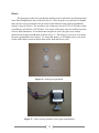
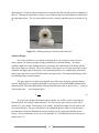
Steel Ball Bearings
The steel balls shown in Fig. 18 serve as the game pieces that mark the placement of the
computer’s move. They were ordered from McMaster-Carr because that company sold steel ball
bearings in the small number we needed. The material was chosen to be E52100 chromium steel
because of its magnetic properties and its resistance to corrosion and oxidation.
Tests have been performed with the steel balls and the electromagnet to determine how
much voltage and current are needed to attract the ball but not attract other balls with it. Nearer
to the completion of the project, the balls will be lightly sanded to help the spray paint adhere
and then spray painted red and green to symbolize hit or miss respectively. There is a slight
concern that sanding may remove a small amount of the chromium on the steel balls which
would decrease the magnetism. This will be accounted for by using magnetic spray paint.
Figure 18 – Steel ball bearings used as markers
24
Ship Sensor Design
Two different sets of rails were being considered for the push button sensing system. The
first set of rails are standard kitchen drawer rails as shown in Fig. 19. The advantage of these
rails is their light weight. Light-weight is desirable since a lot of weight could cause a lag on the
movement of the motor in one direction. Also, they fit perfectly in the space requirements of our
original design. The rails would need to be machined, since the minimum length in which they
are manufactured is 12 inches (30.48 cm). A major disadvantage for using this rail system is the
difficulty of attaching the gear rack to the rail; an additional lubricant will be needed to decrease
friction with that specific model of rails. Also, an extra set of wheels would be needed to ensure
that the gear rack could be moved easily along the whole rail. In addition, Plexiglas pieces will
need to be incorporated to successfully attach the gear rack onto the rails.
Figure 19 - Standard Kitchen Drawer Rails.
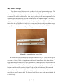
The second set of rails considered are telescopic rails seen in Fig. 20. These rails are heavier
than the other set of rails which could affect the linear movement produced by the motors. They
also come in 12 inch (30.48 cm) lengths and would need to be machined. Also, these rails are
bigger than the expected size, so the space requirements of the original design would need to be
modified. The advantage of using these rails is that no additional wheels need to be incorporated
to attach the rail to the gear rack. Since telescopic rails operate will ball bearings, no additional
lubricant would be needed to reduce friction. For the way the rail is designed, the gear would
need to support a portion of the weight of the rail. However, it was shown in the gear
calculations that the gear teeth will be able to handle roughly four times the maximum load
exerted by the stepper motor’s shaft. The factors of safety are the same as the ones calculated for
the initial design.
25
Figure 20 - Telescopic Rails
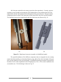
The rails chosen for the sensing system design are the telescopic rails mainly for the ease of
attachment between the gear rack and the rail. To overcome the weight factor mentioned above,
the rails were cut using a horizontal band saw, as shown in Fig. 21, and the outer part of the rail
was removed. The finished product is displayed in Fig. 22.
Figure 21 – Cutting of rails
26
Figure 22 – Rails cut to size
Other than the consideration of an alternative set of rails that will be used for the ship
sensor, the sensing system design has not changed. The system will still consist of a set of rails,
two gear racks, and a gear. The electromagnet will be attached to the end of one rack, and the
push button will be attached to the end of the other rack as shown in Fig. 23.
Electromagnet
Push Button
Figure 23 – Electromagnet and push button incorporated into sensing system
27
All of the parts needed for the sensing system have been purchased. Currently, progress
regarding system assembly and testing have been hindered due to the problems that have been
experienced with the CNC machine for the fabrication of the gear rack pieces. The gear racks’
components interact will all of the other parts of the system; thus, they have not been attached.
The similarity between the original design and the actual sensor are shown in Fig. 24.
(a)
(b)
Figure 24 - Ship Sensor System (a) Assembly (b) SolidWorks model.
The spatial distribution of the different components that are integrated into the sensing
system for final assembly was determined based on the width of the rails, the height of the gear
racks, and the diameter of the gears purchased. A SolidWorks drawing was made to represent the
locations of each of the components on the Plexiglas piece (2.5in. x 2.5in.) that is attached to the
crossmember cart. The final design is shown in Fig. 25.
28
Figure 25 – Final design of sensing system with dimensions.
29
Gears
The four gears needed were purchased according to the requirements specification stated
in the Final Design Report and are shown in Fig. 26. Since the gears were purchased in English
units, the bore size was selected to be the closest to the diameter of the stepper motor’s shaft
which is 5 mm (0.1969 in.). The actual bore size of the gears was 0.1875 in. (4.7625mm), which
is a difference of 0.0094 in. (0.23876mm). The centers of the gears were successfully bored out
to fit the shaft dimensions. It was shown that using the set screw, the gears were securely
attached to the stepper motor’s shaft as shown in Fig. 27. The design of a set screw is such that
the gear is guaranteed to stay in place. To ensure this further, we will lightly sand a very small
section of the shaft to increase friction between the shaft and the set screw.
Figure 26 - Actual gears purchased.
Figure 27 - Gears securely attached to the stepper motor’s shaft
30
Racks
Another modification to the original design is the material selected for the gear racks.
Two different types of plastic bars were purchased. Instead of Nylon 101, acetal (Delrin) and
PVC Type 1 were purchased. This modification was because of the availability on the market
and the cost of the bars in the dimensions that were needed. Even though Delrin has a lower
yield strength compared to Nylon 101, no additional gear calculations are needed since the
previous gear calculations were made using Delrin.
For the fabrication of the gear racks, a CNC program was written using free software
downloaded (CNC Simulator) from www.cncsimulator.com. This software could be used for
non-machine specific simulations. The simulation offers a three-dimensional and a twodimensional simulation at the same time. In this program, the tool position, tool number, and
machining time are specified.
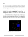
The tool that is being used in the CNC machine to cut the racks is very small (0.03125in.)
(0.79375mm) because of the size restrictions the tooth profile creates. The number of lines of
code to make a small movement increased dramatically to ensure that the tool does not break.
The trimetric view of the tool movement is shown in Fig 28. Even when the dimensions of the
plastic bars are small (18 in. x 0.5 in. x 0.5 in.) (45.72mm x 1.27mm x 1.27mm), the desired
output of the tool needs to be divided into a lot of small intervals.
Figure 28 – Trimetric view of the tool-movement
31
The movement of the tool for the outer edge of the tooth profile is solely in the Y and Z
directions. The inclination of the tooth profile is given by a change in the X. There is an
alternation between G00 mode and G01. G00 is a rapid transverse mode that moves the axes to a
location with a rapid feed rate. It is used for tool movements were no material needs to be cut.
G01 is a linear interpolation mode which adjusts the velocity of the movement to allow material
to be cut.
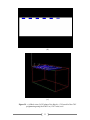
The CNC programming is complete and the code for a single tooth profile can be viewed
in Appendix C. The tooth profile was programmed based on the dimensions available at the
Urley Laboratory. Two different programs were developed to cut the teeth. The first program
uses two different tools. The first is a 0.0625in (1.5875mm) diameter tool to cut straight lines
and remove an initial amount of plastic as shown in Fig. 29. The second part of the program uses
a 0.03125in (0.79375mm) diameter tool in which the “V” shape of the tooth is done with two
different passes to avoid the tool being broken. This process is shown below in Fig. 30. The
advantage of this program is the significant reduction in the time needed to cut every tooth. The
disadvantage is that additional time is needed to change the tool in the machine and to zero the
coordinates to accurately match the two cuts to form the tooth profile. The tools used are shown
in Fig 31.
(a)
32
(b)
(c)
Figure 29 – (a) Block-view (b) XZ plane of the block (c ) 3-D model of the CNC
programming using the 0.0625 in (1.5875 mm) tool.
33
Straight-cut
First-pass
Second-pass
(a)
(b)
34
(c)
Figure 30 – (a) Block-view (b) XZ plane of the block (c ) 3-D model of the CNC
programming using the 0.03125 in (0.7938 mm) tool.
0.03125 in.
(0.7938 mm) diameter
end-mill tool
0.0625 in.
(1.5875 mm) diameter
end-mill tool
Figure 31 – Tools used to cut the gear racks.
35
Preliminary testing was done using the first program. PVC Type 1 was used to test the
code on the CNC machine as shown in Fig. 32. The tooth was successfully cut with a good
surface finish. The second program was developed using the smaller tool that does the straight
cut and the “V” shape. It is the fastest way to cut the tooth profile since it avoids the tool being
changed and eliminates the error produced by the alignment of the smaller tool with the cut done
with the larger tool.
Tooth cut using two
different tools.
Teeth cut using one
tool.
Figure 32 – Experimental cutting of teeth using two different CNC programs. Material used is
PVC Type 1.
In Fig 33, it can be seen that for the teeth cut using one tool, the plastic melted and even
when the tooth profile was done correctly, the surface finish was poor. This was mostly due to
the fact that the cutting speed was too high, the feed rate was too high, and the tool became hot.
Figure 33 – Experimental cutting of teeth using two different CNC programs. (PVC Type 1)
36
From the experimentation using PVC Type 1, it was determined that the teeth needed to
be cut using the program that incorporated two different tool sizes. To determine the settings for
cleanest cut of the teeth, the feed rate and spindle speed were altered separately. Since these
settings would be used to cut the actual racks, we decided to perform the tests using Delrin. Six
different teeth were cut using the combinations of feed rate and spindle speed specified in Table
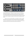
3. The results can be seen in Fig. 34.
Table 3: Testing used for the experimentation using Delrin
Tooth Number
Feed Rate
(in./min)
Spindle Speed
(rev/min)
1
1
1000
2
1
2000
3
1
3000
4
2
1000
5
2
2000
6
2
3000
Tooth # 1
Figure 34 – Testing results using Delrin with different feed rates and spindle speeds.
It was determined that the best tooth cut was done using the lowest feed rate and the
lowest spindle speed. At higher feed rates and spindle speeds, the plastic started melting and
produced an accumulation of melted plastic inside the cut as was seen in Fig. 33. The
disadvantage of this combination of feed rate and spindle speed is the time needed to complete
the cuts. Using this combination, the average time needed to cut one inch of material is
approximately 2 hours. The parts needed for the project are 3 racks of 18 inches (45.72 cm) each
and 2 racks of 7 inches (17.78 cm) each. The total time required to cut all the racks needed is
37
approximately 136 hours without taking into account the time delay produced by the changing of
the tool. Through the preliminary testing, it was confirmed that the programming was done with
the right dimensions. The cut teeth meshed correctly with the purchased gears as shown in Fig.
35.
Figure 35 – Meshing of the gear and cut teeth on the rack
Alternate Design
Due to the problems we are facing with being able to successfully cut the racks in a
timely manner, an alternate design is being considered as a potential backup. The major
roadblock right now is that without the gear racks ready, the construction of the frame and the
ship sensor design are delayed. These two modules of the project are of great importance as they
constitute the biggest part of the project. One potential option we are considering is purchasing
metric gears and racks to avoid the fabrication of the gear racks. The major disadvantage would
be the budget that it would consume.
The gear analysis was done using English units. However, most gear equations that are
used for English gears are equally applicable to metric gears if the module ‘m’ is substituted for
diametral pitch. The relationship between diametral pitch and module is shown in Eq. 1, where m
is the module and
is the diametral pitch.
=
.
(1)
In our previous design, the diametral pitch chosen was 24 DP, so after converting the
diametral pitch, the module is approximately 1. For this reason, gears and gear racks with a
module of 1 were chosen. The material, style, quality, and pressure angle were the same as the
ones selected before. The gear calculations were computed again to make sure the alternative
gear and rack selection will handle the stresses produced by the movement and ship sensor
system. These calculations can be viewed in Appendix D. A SolidWorks sketch of the gear is
shown in Fig. 36.
38
Gear Specifications
Manufacturer: Stock Drive Products Sterling Instruments SDP/SI
Part Number: A 1Z 2MYZ1002405
Unit: Metric
Module: 1
No. Of Teeth: 24
Material: Acetal - Brass insert
Style: Pin Hub – with Set Screw
Quality: Class Commercial –Molded-
Figure 36 – Alternative Metric Gear
Bore Size: 5 mm
Pressure Angle: 20°
Face Width: 9 mm
Pitch Dia.: 24 mm
Hub Dia.: 15 mm
Rack Specifications
Part Number: A 1M12MYZ1025
Module: 1
Pressure Angle: 20°
Material: Acetal Molded
Quality Class: ISO 8 (AGMA Q9)
Stock Length: 250 mm
Face Width: 9 mm
Height: 9 mm
Pitch Height: 8 mm
39
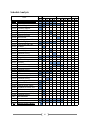
Budget Analysis
Item
Push Button for Ship Sensor
Steel Balls
Motors
LCD Screen
LEDs
Electromagnet
Movement Rails
Gears
Ship Sensor Rails
PVC Type 1
Quad SR Latches
Quad 2 Input NAND Gates
Push Buttons for Keypad
Plexiglas
Binding
Delrin Bars
Silicone and Superglue
Diodes, Demultiplexors,Voltage Regulators
Superglue
Transformer and Transistors
Spent
$9.15
$33.77
$96.56
$24.41
$33.00
$37.21
$14.52
$32.96
$9.67
$3.90
$47.00
$8.92
$11.80
$165.22
$2.00
$32.50
$8.33
$17.96
$14.04
$30.00
$632.92
Estimated
Cost
$100.00
$10.00
$15.00
$125.00
Unpurchased Items
Professional Etching Board
Schmart Board
Small Circuit Supplies
Actual costs and anticipated costs match the budget well. We have purchased $633 and
still have to purchase approximately $125 of supplies. This $125 is for a dual layer professional
PCB, a Schmart Board, and small circuit components. Out of the total of $850 that we are
allowed to spend, we expect to spend $758, but will probably have a few small things such as a
little extra PCB cost or a few extra resistors which will put out total around $780. This is
approximately 92% of our allotted budget leaving 8% or $70 for anything we have missed.
40
Schedule Analysis
Tasks
S 1.0
S1.1
S1.1.1
S1.1.2
S1.1.3
S1.1.4
S1.1.5
S1.1.6
S1.1.7
S1.2
S1.2.1
S1.2.2
S1.2.3
S1.2.4
S1.2.5
S1.3
S1.3.1
S1.3.2
S1.3.3
S1.3.4
S1.4
S1.4.1
S1.5
S1.5.1
S1.5.2
S1.5.3
S1.6
S1.6.1
S1.6.2
S1.6.3
S1.6.4
S1.6.5
S1.6.6
S1.7
S1.7.1
S1.7.2
S2.0
Feb
28
March
14 21
S
P
R
I
N
G
7
Parts Assembly and Testing
Frame Construction
Finish Milling to Size
Assemble Hoppers
Rails andWalls
Upper Display
Movement System
Game Boards
Remaining Walls and Covers
Ship Sensing System
Finish Design and Code
Cut Racks
Make Ship Pieces
Assemble System
Individual Testing
LED
Design PCB
Send For Etching
Assembly
Individual Testing
LCD
Individual Testing
Keypad
Etch Board
Assemble Keypad Elements
Individual Testing
Power Supply
Fix Motor Current Issue
Redesign Power Supply
Breadboard Circuit & Test
Etch board
Assemble Power Supply
Individual Testing
Microcontroller
Write code
Write Test Code
Midterm Progress Report
B
R
E
A
K
!
!
!
S
P
R
I
N
G
B
R
E
A
K
!
!
!
S
P
R
I
N
41
28
4
April
11 18
25
May
2
9
S2.1
S2.2
S3.0
S4.0
S5.0
S6.0
S6.1
S6.2
O4.0
O5.0
O6.0
Report
Presentation
System Integration
System Testing
Finalize Prototype
Project Readiness Review
Report
Presentation
Documentation
A3 Status Reports
Time Management
G
B
R
E
A
K
!
!
!
The schedule above is our updated schedule. The old schedule was created at the
beginning of the project and some components of the project have been removed while others
have been altered tremendously. Also, because we had been set back due to the complexity of
the LED PCB design and the gear rack fabrication, those parts of the schedule needed to be
revised. This new schedule will keep us on track much better and we can reference it weekly to
see exactly what needs to be done. The previous schedule merely had the duration of each whole
module, but this new schedule has a breakdown of tasks that need to be completed within each
module.
Because we have just revised the schedule, we are completely on schedule. We should
have about three weeks to have all of the finished modules implemented, tested and debugged.
They will have all been individually tested so it is merely a matter of getting each module to
work with every other module. We are sure that we can have our prototype completed and fully
functioning as described in the Requirements Specification by the end of April.
42