1
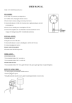
CZE-T251 User Manual 1. Attention before use: 1) Make sure the supplied voltage is within the acceptable range. 2) Only professionals can do the maintenance. 3) Please make sure the antenna has lightening protection. 4) Please don’t touch the antenna when the machine is connected with power supply. 5) Please don’t power on the machine without connecting antenna. 6) Please don't use the transmitter in explosive environment(e.g. gas station, places with gas or steam) 7) Please don’t use the transmitter in extreme dusty, damp, hot environment. 8) Please use the transmitter under the regulations by local wireless administration institutions. 2. Menu 1) Product features 2) Product configuration 3) Product user guide 4) Product specification 5) Troubleshoot 3. Product Features CZE-T251 is a multi-functional FM transmitter. It has stable structure, excellent performance , super good sound quality and is very easy to use. *Main Features: -Stereo/Mono optional - RF output power is continuously adjustable from 0~25watt. -One button controls all functions. -SWR protection. When antenna is not well connected, the transmitter will turn to protection mode automatically. -Temperature protection. When the temperature of transmitter is too high, it will turn to protection mode automatically. 4. Product configuration NO NAME DESCRIPTION QTY UNIT PORT 1 FM transmitter CZE-T251 1 PCS NO 2 ALLUMINUM ANTENNA 1/4 1 SET RF OUT 3 POWER ADAPTER DC12V/6A 1 SET 12.0V-6.0A 4 AUDIO CABLE 1 TO 2 - 3.5m TO RCA 1 PCS LINE IN 5 USER MANUAL ELECTRONIC VERSION 1 PCS NO 5. User Guide 1) Front and Back Panel description Front Panel Back Panel 2) Knob description Action Definition Description Main page, adjusting page, shift ( turn clockwise to increase, turn Turn left/right Adjust, shift Short press Confirm Enter/Exit Menu page Press hold Confirm On Main page, press and hold to enter Menu and Counterclockwise to reduce) 3) Operation Instruction a) Turn ON Check the antenna first, make sure it’s well connected. Then connect the power cord to home socket, press the power button to I position to turn ON the transmitter. O position means OFF. See picture on the right. After power on, the transmitter goes into working status. Real-time working frequency: Real-time internal working temperature: RF output power: SWR: Sound Mode: Line-in Volume: Microphone Volume: means Stereo, means Mono , the range is 0~79 , the range is 0~79 b) Function and Parameter setting Press the knob to enter Menu page. Turn the knob to shift pages. There are 9 pages altogether rotating on the screen. Frequency setting On the Menu page, turn the knob to page 1 FERQ setting, press the knob to enter setting(the RF output will be shut down temporarily). Turn the knob to adjust the frequency by stepping of 0.1MHz, then press the knob to confirm setting and exit. Line-in Volume setting On the Menu page, turn the knob to page 2 LINE VOLUME setting, press the knob to enter setting. Turn the knob to adjust the volume within the range of 0~79, then press the knob to confirm setting and exit. MIC volume setting On the Menu page, turn the knob to page3 MIC VOLUME setting, press the knob to enter setting. Turn the knob to adjust the microphone volume within the range of 0~79, then press the knob to confirm setting and exit. RF output power setting On the Menu page, turn the knob to page 4 RF POWER setting, press the knob to enter setting. Turn the knob to adjust the output power within the range of 0~50w, then press the knob to confirm setting and exit. Sound mode setting On the Menu page, turn the knob to page 5 ST<OR>MO setting, press the knob to enter setting. Turn the knob to shift the sound mode between Stereo and Mono, then press the knob to confirm setting and exit. Temperature Protection Setting On the Menu page, turn the knob to page 6 TEMP setting, press the knob to enter setting. Turn the knob to adjust the protection temperature point within the range of 30~80℃, then press the knob to confirm setting and exit. SWR protection setting On the Menu page, turn the knob to page 7 SWR SET setting, press the knob to enter setting. Turn the knob to adjust the SWR protection point within the range of 1.0~5.0, then press the knob to confirm setting and exit. Line Mute setting On the Menu page, turn the knob to page 8 MUTE setting, press the knob to enter setting. Turn the knob to set Mute status, ON means the line-in is muted, OFF means the line-in is available. Press the knob to confirm setting and exit. Exit setting On the Menu page, turn the knob to page 9 MENU EXIT, press the knob to exit setting and return to main page. Remark: In the MENU page, if there is no action within 20 seconds, the system will return to Main page automatically. 6. Technical Specification NO Item Specification 1 Working Voltage 12V 2 Working Current ﹤5A 3 Frequency Range 87~108MHz 4 Frequency Stability ±10PPM 5 Frequency Stepping 100KHz 6 Environment temperature -10℃~45℃ 7 Output Impedance 50Ω 8 RF output power 0W~25W 9 Harmonic, clutter radiation ≤-60dB 10 Audio distortion 0.2% 11 Frequency Response 50Hz~15000Hz 12 Separation ≥35 dB 13 Input level ≤15 dBV 14 Frequency Modulation ±75KHZ 15 SNR ≥70dB 16 Size 210 ㎜(L)*174 ㎜(W)*59 ㎜(H) (Exclude projected parts) 17 Net Weight About 1.5kg 7. Troubleshooting NO 1 2 Problem description Possible Reasons Unable to Power ON 1)Socket is not connected with electricity 2)Power cord is not well plugged. 3)The fuse is not working properly in socket. SWR Alarm 1)Antenna is not well connected. 2)SWR value is too high because antenna doesn’t match transmitter 3) There are too many reflecting objects close to antenna. Temperature Alarm 1)Fan is not working; 2)Antenna doesn't match transmitter, the SWR value is too high, thus temperature rises up. 3)The fan holes are jammed. SWR value is too high 1)Antenna not well connected. 2)SWR value is too high because antenna doesn’t match transmitter 3) There are too many reflecting objects close to antenna. 5 Short transmitting distance 1)High loss of feeder cable. 2)Poor broadcasting environment. 3)Output power is low. 4)Antenna is not placed high enough. 5)Antenna and transmitter doesn’t match. 6)Radio receiver has low sensitivity. 6 No power output 1) RF output power needs to be adjust higher 2) Transmitter is powered OFF. 7 No audio output 1)Transmitter line-in volume is too low. 2)Line-in audio signal is abnormal. No microphone output 1)Microphone is not working well. 2)Microphone volume is too low. 3)Microphone is dynamic type. 4)Microphone is not well plugged. Poor sound quality 1)Microphone quality is low. 2)Audio source quality is low. 3)Antenna is not well assembled and connected. 4)Audio signal or transmitter line-in volume is not adjusted well. 3 4 8 9