1
Copyright
This manual and any accompanying software and firmware are copyrighted.
No parts of this publication may be reproduced, stored in a retrieval system, or
transmitted, in any form or by any means, electronic, mechanical, photocopy,
recording, or otherwise, without prior written consent except for copies
retained by the purchaser for backup purposes.
Trademarks
Product and company names mentioned in this manual are for identification
purposes only and may be trademarks of their respective companies.
Microsoft and Windows are registered trademarks of Microsoft Corporation.
ICA, MetaFtrame, WinFrame are registered trademarks of Citrix Systems, Inc.
Disclaimer
The information described in this manual is intended for instructional purposes
only. The Vendor reserves the right to revise this manual and all accompany
software, firmware without obligation to notify any person or organization of the
revision or change. The Vendor accepts no responsibility or liability for errors
or misleading information that may be contained in this manual.
Radio Frequency Interference Statement
FCC Statement
This equipment has been tested and found to comply with the limits for a Class
B digital device, pursuant to Part 15 of FCC Rules. These limits are designed
to provide reasonable protection against harmful interference when the
equipment is operated in a residential installation. This equipment generates,
uses, and can radiate radio frequency energy. if it is not installed and used in
accordance with the instructions, may cause harmful interference to radio
communications. However, there is no guarantee that interference will not
occur in a particular installation. If this equipment does cause harmful
interference to radio or television reception, which can be determined by
turning the equipment off and on, the user is encouraged to try to correct the
interference by one or more of the following measures:
1
Reorient or relocate the receiving antenna.
Increase the separation between the equipment and receiver.
Connect the equipment into an outlet on a circuit different from that to which
the receiver is connected.
Consult the dealer or an experienced radio TV technician for help.
Notice:
The changes or modifications not expressly approved by the party responsible
for compliance could void the user's authority to operate the equipment.
IEC/EN Notice
This product conforms to the requirement of IEC950 and EN60950.
This product conforms to requirements of EN55022 for Class A equipment or
EN55022 for Class B equipment.
2
End User License Agreement ("EULA") for MICROSOFT WINDOWS CE
OPERATING SYSTEM FOR WINDOWS-BASED TERMINAL DEVICES
VERSION 1.0
IMPORTANT-READ CAREFULLY:
This End User License Agreement (“EULA”) is a legal
agreement between you (either an individual or a single entity) and the manufacturer (“Manufacturer”) of the special
purpose computing device (“SYSTEM”) you acquired which includes certain Microsoft software product(s) installed on
the SYSTEM and/or included in the SYSTEM package (“SOFTWARE”). The SOFTWARE includes computer software,
the associated media, any printed materials, and any “online” or electronic documentation. By installing, copying
downloading, or otherwise using the SOFTWARE, you agree to be bound by the terms of this EULA. If you do not agree
to the terms of this EULA, Manufacturer and Microsoft Licensing, Inc. (“MS”) are unwilling to license the SOFTWARE to
you. In such event, you may not use or copy the SOFTWARE, and you should promptly contact Manufacturer for
instructions on return of the unused product(s) for a refund.
SOFTWARE LICENSE
The SOFTWARE is protected by copyright laws and international copyright treaties, as well as
other intellectual property laws and treaties. The SOFTWARE is licensed, not sold.
GRANT OF LICENSE. SOFTWARE includes software already installed on the
SYSTEM (“SYSTEM Software”) and, if included in the (Desktop Software”).
This EULA grants you the following rights to the SOFTWARE:
․SYSTEM Software. You may use the SYSTEM Software only as installed in the
SYSTEM.
․Desktop Software.
Desktop Software might not be included with your SYSTEM. If
Desktop Software is included with your SYSTEM, you may install and use the component(s) of
the Desktop Software in accordance with the terms of the end user license agreement
provided with such component(s). In the absence of the a separate end user license
agreement for particular components(s) of the Desktop Software, you may install and use only
one (1) copy of such component(s) on a single computer with which you use the SYSTEM.
․Use of Windows CE Operating System for Windows-Based Terminal
Devices with Microsoft Windows NT Server, Terminal Sever Edition. If the
SOFTWARE is Windows CE operation system for Windows-Based Terminal devices, the
following special provisions apply. In order to use the SYSTEM in connection with Windows
NT Server, Terminal Server Edition, you must possess (1) a Client Access License for
Windows NT Server, Terminal Server Edition and (2) an end user license for Windows NT
Workstation or an end user license agreement for Windows NT Workstation for
Windows-Based Terminal Devices (please refer to the end user license agreement for
Windows NT Server, Terminal Sever Edition for additional information). Manufacturer may
have included a Certificate of Authenticity for Windows NT Workstation for Windows-Based
Terminal Devices with the SYSTEM. In that case, this EULA constitutes an end user license
3
for the version of Windows NT Workstation for Window-Based Terminal Devices indicated on
such Certificate of Authenticity.
․Back-up Copy. If Manufacturer has not included a back-up copy of the SYSTEM
Software with the SYSTEM, you may make a single back-up copy of the SYSTEM Software.
You may use the back-up copy solely for archival purposes.
DESCRIPTION OF OTHER RIGHTS AND LIMITATIONS.
․ Speech/Handwriting Recognition. If the SYSTEM Software includes speech
and/or handwriting recognition component(s), you should understand that speech and
handwriting recognition are inherently statistical processes; that recognition errors are inherent
in the processes; that it is your responsibility to provide for handling such errors and to monitor
the recognition processes and correct any errors. Neither manufacturer nor its suppliers shall
be liable for any damages arising out of errors in the speech and handwriting recognition
processes.
․Limitations on Reverse Engineering, Recompilation and Disassembly.
You may not reverse engineer, recompiles, or disassemble the SYSTEM Software, except and
only to the extent that such activity is expressly permitted by applicable law notwithstanding
this limitation.
․Single SYSTEM.
The SYSTEM Software is licensed with the SYSTEM as a single
integrated product. The SYSTEM Software installed in Read Only Memory ("ROM") of the
SYSTEM may only be used as part of the SYSTEM.
․Single EULA.
The package for the SYSTEM Software may contain multiple versions
of this EULA, such as multiple translations and/or multiple media versions (e.g., in the user
documentation and in the software). Even if you receive multiple versions of the EULA, you are
licensed to use only one (1) copy of the SYSTEM Software.
․Rental.
You may not rent or lease the SOFTWARE.
4
․Software Transfer.
You may permanently transfer all of your rights under this EULA
only as part of a sale or transfer of the SYSTEM, provided you retain no copies, you transfer all
of the SOFTWARE (including all component parts, the media, any upgrades or backup copies,
this EULA and, if applicable, the Certificate(s) of Authenticity), and the recipient agrees to the
terms of this EULA. If the SOFTWARE is an upgrade, any transfer must include all prior
versions of the SOFTWARE.
․Termination.
Without prejudice to any other rights, Manufacturer or MS may terminate
this EULA if you fail to comply with the terms and conditions of the EULA. In such event, you
must destroy all copies of the SOFTWARE and all of its component parts.
․UPGRADES.
If the SYSTEM Software and this EULA are provided separate from the
SYSTEM by Manufacturer and the SYSTEM Software is on a ROM chip, CD ROM disk(s) or
floppy disk(s), and labeled "For ROM Upgrade Purpose Only" ("ROM Upgrade"), you may
install one copy of the ROM Upgrade onto the SYSTEM as a replacement copy for the
SYSTEM Software originally installed on the SYSTEM and use it in accordance with Section 1
of this EULA.
․COPYRIGHT.
All title and copyrights in and to the SOFTWARE (including but not
limited to any images, photographs, animations, video, audio, music, text and “applets,”
incorporated into the SOFTWARE), the accompanying printed materials, and any copies of the
SOFTWARE, are owned by MS or its suppliers (including Microsoft Corporation). You may not
copy the printed materials accompanying the SOFTWARE. All rights not specifically granted
under this EULA are reserved by MS and its suppliers (including Microsoft Corporation).
․PRODUCT SUPPORT.
Product support for the SOFTWARE is not provided by MS,
its parent corporation, Microsoft Corporation, or their affiliates or subsidiaries. For product
support, please refer to Manufacturer’s support number provided in the documentation for the
SYSTEM. Should you have any questions concerning this EULA, or if you desire to contact
Manufacturer for any other reason, please refer to the address provided in the documentation
for SYSTEM.
5
․EXPORT RESTRICTIONS.
You agree that you will no export or re-export the
SOFTWARE to any country, person, or entity subject to U.S. export restrictions. You
specifically agree no to export or re-export the SOFTWARE: (i) to any country to which the U.S.
has embargoed or restricted the export of goods or services, which as of March 1998include,
but are not necessarily limited to Cuba, Iran, Iraq, Libya, North Korea, Sudan and Syria, or to
any national of any such country, wherever located, who intends to transmit or transport the
products back to such country; (ii) to any person or entity who you know or have reason to
know will utilize the SOFTWARE or potion thereof in the design, development or production of
nuclear, chemical or biological weapons; or (iii) to any person or entity who has been
prohibited from participating in U.S. export transactions by any federal agency of the U.S.
government. If the SOFTWARE is labeled “North America Only Version” above, on the
Products Identification Card, or on the SOFTWARE packaging or other written materials, then
the following applies: The SOFTWARE is intended for distribution only in the United States, its
territories and possessions (including Puerto Rico, Guam, and U.S. Virgin Islands) and
Canada. Export of the SOFTWARE from the United States is regulated under “EI controls” of
the Export Administration Regulations (EAR, 15 CFR 730-744) of the U.S. Commerce
Department, Bureau of Export Administration (BXA). A license is required to export the
SOFTWARE outside the United States or Canada. You agree that you will not directly or
indirectly, export or re-export the SOFTWARE (or portions thereof) to any country, other than
Canada, or to any person or entity subject to U.S. export restrictions without first obtaining a
Commerce Department Export license. You warrant and represent that neither the BXA nor
any other U.S. federal agency has suspended, revoked or denied your export privileges.
6
․NOTE ON JAVA SUPPORT.
The SYSTEM Software may contain support for
programs written in Java. Java technology is not fault tolerant and is not designed,
manufactured, or intended for use or resale as on-line control equipment in hazardous
environments requiring fail-safe performance, such as in the operation of nuclear facilities,
aircraft navigation or communication systems, air traffic control, direct lie support machines, or
weapons systems, in which the failure of Java technology could lead directly to death,
personal injury, or severe physical or environmental damage.
LIMITED WARRANTY
․ Limited Warranty. Manufacturer warrants that the SOFTWARE will perform
substantially in accordance with the accompanying written materials for a period of ninety (90)
days from the date of receipt. Any implied warranties on the SOFTWARE are limited to ninety
(90) days. Some states/jurisdictions do not allow limitations on duration of an implied warranty,
so the above limitation may not apply to you.
․ Customer Remedies.
Manufacturer’s and its suppliers entire liability and your
exclusive remedy shall be, at Manufacturer’s option, either (a) return of the price paid, or (b)
repair or replacement of the SOFTWARE that does not meet the above Limited Warranty and
which is returned to Manufacturer with a copy of your receipt. This Limited Warranty is void if
failure of the SOFTWARE has resulted from accident, abuse, or misapplication. Any
replacement SOFTWARE will be warranted for the remainder for the original warranty period
or thirty (30) days, whichever is longer.
․No Other Warranties. EXCEPT AS EXPRESSLY PROVIDED IN THE LIMITED
WARRANTY SECTION ABOVE, THE SOFTWARE IS PROVIDED TO THE END USER “AS
IS” WITHOUT WARRANTY OF ANY KIND, EITHER EXPRESSED OR IMPLIED, INCLUDING,
BUT NOT LIMITED TO, WARRANTIES OF NON-INFRINGEMENT, MERCHANTABILITY,
AND/OR FITNESS FOR A PARTICULAR PURPOSE.
THE ENTIRE RISK OF THE
QUALITY AND PERFORMANCE OF THE SOFTWARE IS WITH YOU.
․ No
Liability
for
Consequential
Damages.
MANUFACTURER
OR
MANUFACTURER’S SUPPLIERS, INCLUDING MS AND ITS SUPPLIERS, SHALL NOT BE
HELD TO ANY LIABILITY FOR ANY DAMAGES SUFFERED OR INCURRED BY THE END
USER (INCLUDING, BUT NOT LIMITED TO, GENERAL, SPECIAL, CONSEQUENTIAL OR
INCIDENTAL DAMAGES INFORMATION AND THE LIKE), ARISING FROM OR IN
CONNECTION WITH THE DELIVERY, USE OR PERFORMANCE OF THE SOFTWARE.
7
If you acquired this EULA is the United States, this EULA is governed by the
laws of the State of Washington.
If you acquired this EULA in Canada, this EULA is governed by the laws of the
Province of Ontario, Canada. Each of the parties hereto irrevocably attires to
the jurisdiction of the courts of the Province of Ontario and further agrees to
commence any litigation which may arise hereunder in the courts located in
the Judicial District of York, Province of Ontario.
If this EULA was acquired outside the United States, then local law may apply.
Should you have any questions concerning this EULA, please contact the
Manufacturer of your SYSTEMS.
U.S. GOVERNMENT RESTRICTED RIGHTS
The SOFTWARE and documentation are provided with RESTRICTED
RIGHTS. Use, duplication, or disclosure by the Government is subject to
restrictions as set forth in subparagraph (c)(1)(ii) of the Rights in Technical
Data and Computer Software clause at DFARS 252.227-7013 or
subparagraphs(c)(1)
and
(2)
of
the
Commercial
Computer
Software—Restricted Rights at 48 CFR 52.227-19, as applicable.
Manufacturer is Microsoft Corporation/One Microsoft Way/Redmond, WA
98052-6399.
8
INTRODUCTION
INTRODUCING THE THINCLIENT
FEATURES OF THINCLIENT TC-620 SERIES
HARDWARE SETUP
UNPACKING & CHECKING THE EQUIPMENT
IDENTIFY PARTS OF THE THINCLIENT TC620
CONNECTING THE TERMINAL
USING THE POWER ON/OFF SWITCH
START UP
12
12
13
15
15
16
18
18
19
QUICKLY CONFIGURE YOUR THINCLIENT
19
TERMINAL CONNECTION MANAGER
24
DEFAULT CONNECTION
Media Player
Imager Viewer
ADDING A NEW CONNECTION
Creating a new ICA Client Connection
Creating a new RDP Connection
Creating a Internet Explorer Connection
Creating a Terminal Emulator
Creating a Dial-Up Connection
Creating a Direct Connection
Creating a Virtual Private Network Connection
Creating a PPPoE connection
CONFIGURE AN EXISTING CONNECTION
CONNECTING TO A SERVER
25
25
26
27
30
33
36
37
38
40
41
42
43
46
AUTO CONNECTING
VNC MONITOR AGENT
47
62
CHANGING THE TERMINAL PROPERTIES
INTERNET OPTION
General
Connection
Security
Privacy
Advanced
48
49
49
49
50
50
51
9
Pop-ups
CERTIFICATES
DATE/TIME
DIALING PROPERTIES
DISPLAY
ETHERNET PROPERTIES
FIRMWARE
GLOBAL ICA CLIENT SETTINGS
Keyboard Shortcuts
Preferences
Server Location
Firewall Settings
KEYBOARD PROPERTIES
LINE PRINTER
51
52
52
52
53
54
54
55
56
56
57
57
58
58
MOUSE PROPERTIES
NETWORK SETTINGS
OWNER
REGIONAL AND LANGUAGE SETTINGS
SECURITY
SYSTEM PROPERTIES
TERMINAL SERVER CLIENT LICENSES
THINPRINT CLIENT CONFIGURATION
TOUCH PANEL PROPERTIES
VOLUME & SOUND PROPERTIES
WIRELESS PROPERTIES
TCP/IP Settings for Wireless LAN
Card Setup
58
59
59
59
60
60
61
61
62
63
63
63
64
SLAVE SMART CARD FOR THINCLIENT
SMART CARD FEATURES:
HOW TO USE THE SLAVE SMART CARD ON THIN CLIENT
Login with NEW Slave Smart Card
Change to a New Pin Number
USING SMART CARD ON A THINCLIENT WITH EXISTING CONNECTION
USING SMART CARD AT POWER ON
TERMINAL SMART CARD PROPERTIES
Smart Card Pin Number
Connection Information
Erasing Smart card contents
66
66
66
66
67
67
69
69
69
70
71
10
BIOS UPGRADE
72
OPERATION SYSTEM RECOVERY
72
11
Introduction
Introducing the ThinClient
ThinClient Windows Based Terminals are designed to access any Windows
application such as Microsoft Word, Excel or PowerPoint residing on Windows
Terminal Server. ThinClient is easy to implement and built with user-friendly
interface. Simply plug a ThinClient onto the network, configure ThinClient,
and then connect to Windows Terminal Server to run Windows applications.
ThinClient supports RDP (Remote Desktop Protocol) and Citrix ICA
(Independent Computing Architecture). Built with extreme flexibly, ThinClient
can connect to one or more Windows NT-based Servers via RDP, Citrix
MetaFrame or WinFrame capable with ICA.
12
Features of ThinClient TC-620 Series
Model
TC-600 Thin Client
Processor
CPU
VIA Luke 800Hz/1GHz
Memory
RAM
One SDRAM 144pin DIMM 128MB up to 512MB
DOM
One Disk on chip flash ROM 32MB up to 144MB
Standard Interface
VGA
up to 2048×1536x32bit ture color, VESA monitor support with DDC
LAN
One 10/100BaseT fast Ethernet port, twisted pair RJ45
Wireless LAN
USB Wireless LAN 802.11b/g (Option)
Smart Card
One Smart Card (Option)
PS2
Support PS2 KB, Mouse
Serial
Two RS232, 9Pin DSUB COM1, COM2
Parallel
25Pin DSUB
USB Port
2 x USB 2.0 Ports (Front), 2 x USB 2.0 Ports (Back)
Audio Line Out
1/8inches mini, full 18bit stereo, 44KHz sample rate
Power System
Connector
2 Pin Jack 5V DC.
AC/DC Adapter
Input AC 100/240 Volt, 50~60Hz. Output 12VCD, 4.2A
Physical Mechanical
Dimension
220 mm (H) x 45 mm (W) x 155 mm (D)
Client Side System Software
OS System
Microsoft Windows CE 5.0
Terminal
IBM: 3270, 5250 for Display and Printer
Emulations
Digital: VT52, VT100, VT220-7, VT220-8, VT320-7, VT320-8, VT420-7, VT420-8,
Supports SSH
VT525-7, VT525-8
(Option)
ANSI: SCO ANSI, BBS ANSI, AT 386, AIXTERM, LINUX, XTERM, WYSE 370
General Terminals: TANDEM, HP, DG, SIEMENS, IBM 3151
ASCII Terminals: WYSE 50, WYSE 50+, WYSE 60, TVI 910+, TVI 920, TVI 925, TVI
950, TVI 955, ADDS VP A2, HZ 1500
Local Browser
IE 6.0
Connectivity
Microsoft Remote Desktop Protocol, RDP5.5
Citrix ICA Protocol, ICA 9.0
Server Side System Software
13
Management Tool AXUS ThinClient Remote Manager
14
Hardware Setup
Unpacking & Checking the Equipment
Before unpacking the ThinClient, prepare a clean, stable surface to put the
contents of your ThinClient shipping container on. You should find following
items in the ThinClient package:
The ThinClient TC620
One AC Adapter
A Power Cord
A Stand for your ThinClient
User's Manual
*A PS/2 Keyboard with cable
*A PS/2 Mouse with cable
The ThinClient TC820
One AC Adapter
A Power Cord
User's Manual
PS/2 Mouse, Keyboard spilt cable
*A PS/2 Keyboard with cable
*A PS/2 Mouse with cable
Notice:
*PS/2 Keyboard and Mouse are optional items.
15
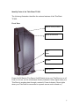
Identify Parts of the ThinClient TC620
The following illustration identifies the various features of the ThinClient
TC620.
Front View
Network Activity Indicator
Power On/Off Switch
USB 1
USB2
Speaker
Microphone
Power On/Off Switch (The Power On/Off Switch turns your ThinClient on or off.
Push it in for on, out for off) Network Activity Indicator (Yellow lights when your
ThinClient is sending data through a network) Power Indicator (Green lights
when your ThinClient is connected to a power source and is turned on)
16
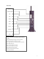
Rear View
Printer Port
Wireless LAN
LAN
VGA
COM2
USB3
USB4
Mouse
Keyboard
Power Connector
COM1
Network , RJ-45 jack for a 10/100BaseT twisted pair Ethernet
connector.
Video, standard DB-15 VGA type connector for Monitor.
Parallel, standard DB-25 parallel port for printer.
COM1, DB-9 RS232 port, for external modem, touch screen .
COM2, DB-9 RS232 port.
USB1, Universal Serial Bus connector.
USB2, Universal Serial Bus connector.
Mouse, PS/2 type mouse connector.
Keyboard, PS/2 type keyboard connector.
Power, Power Connector
17
Connecting the Terminal
Before connecting the cables, arrange your ThinClient and monitor in your
work area. Be sure not to block the ventilations around ThinClient and Monitor.
Plug the AC power core into the power adapter, then into AC power source.
Connect the adapter cable to power connector
Connect the keyboard cable to keyboard connector.
Connect the mouse cable to mouse connector.
Connect the monitor video cable to video connector.
Connect the monitor power cable to the AC power source.
Connect the 10/100Base-T twisted pair network cable to network connector.
If you have a local printer, connect its cable to parallel port.
If you have microphone, plug its cable into microphone port.
If you have headphone or speaker, plug its cable into headphone port.
Using the Power On/Off Switch
After the cables are all connected, you are now ready to turn it on by pressing
power On/Off switch.
To turn on your ThinClient, push the power On/Off switch in. The power
indication light will be led.
To turn off your ThinClient, push the power On/Off switch again and hold for 4
seconds so that it returns to its extended position. The power indication light
will be off.
18
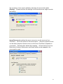
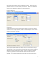
START UP
Quickly Configure Your ThinClient
After completing the hardware setup, the ThinClient must be configured before
it is ready to use. This chapter guides you through the most easy and quick
way to configure your WinClinet. Quick configuring your ThinClient can be
accomplished through following steps:
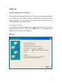
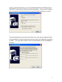
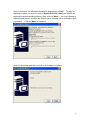
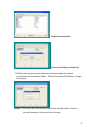
Turn on your ThinClient.
The Welcome setup wizard dialog box is first dialog box when you turn on your
terminal for the first time. Click on the [NEXT] button in the dialog box to
display the next setup wizard dialog box.
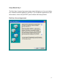
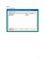
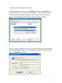
Welcome
19
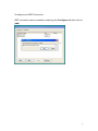
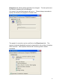
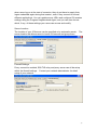
Setup Wizard Step 1
The End User License Agreement setup wizard dialog box is the next dialog
box. Read the license agreement carefully. If you accept the agreement to use
this terminal, click on the [ACCEPT] and continue with setup process.
End User License Agreement
20
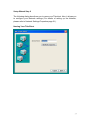
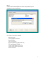
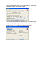
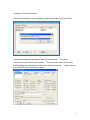
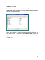
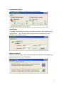
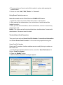
Setup Wizard Step 2
The following dialog box allows you to name your Thinclient. Also, it allows you
to configure your Network settings (For details of setting up the Network,
please refer to Network Settings Properties page 51).
Naming Your ThinClient
21
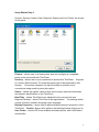
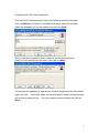
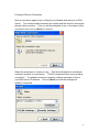
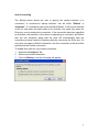
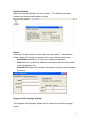
Setup Wizard Step 3
Printers, Security, Owner, Date, Regional, Display and Line Printer are all part
of this panel.
Printers – allows user to choose printer port and configure a compatible
printer to be connected with ThinClient.
Security – allows user to put a password to protect this ThinClient. At power
on, Screen Saver resume, F2 properties panel can all be protected by this
function. Connection manager can also be hidden to prevent more
connections being made by using this option.
Owner – allows the rightful owner of this client to input personal information
and network identification on the ThinClient.
Date/Time – allows ThinClient to be adjusted to the current local time.
Regional Settings – allows ThinClient to be regionalized. The settings within
consist of locale, Interface language, input language.
Display Properties – allows user to adjust desktop area and resolution of the
ThinClient. Caution: Always click perform test settings before clicking on ok.
Line Printer – allows LPD to be enabled and share printer with UNIX based
server/client.
22
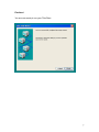
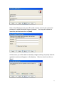
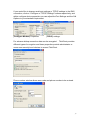
Finalized
You are now ready to run your ThinClient
23
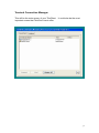
Terminal Connection Manager
This will be the main screen of your ThinClient.
important screen that ThinClient has to offer.
It could also be the most
24
Default Connection
Media Player
Media Player enables user to open a steam media and play it. User can
specify the location of media file which he would like to play. It allows the path
of internet or external storage such as USB Disk.
y
Windows Media Buffering:
To specifies the buffering time (up to 5 seconds). The longer the buffer time,
the longer it takes for streaming content to begin playing.
y
Playback:
Play once: the selected media file will be played once.
Repeat forever: When repeat is turned on, a selected media file can be
played repeatedly.
Zoom: There are four types to view a selected media file
Full Screen: view a video using the entire screen.
50%: Screen zooms to 50%
25
100%: Screen zooms to 100%
200%: Screen zooms to 200%
y
Volume: enable user to adjust volume or mute.
y
Default path of file: Select the media file to play from external storage, or
network using HTTP or MMS format.
For instance of HTTP: http://1.1.1.1/play.mpg.
For instance of MMS: mms://1.1.1.1/play.mpg
Imager Viewer
User can view the picture or images using Imager Viewer.
folder to show pictures or images, where you can:
y
y
y
y
y
To specify the
Scroll through the images in the folder.
Increase or decrease the image preview size.
View the image in full size or as the best fit for your window.
View a slide show of all your images, or select the set of images you’d
like to view in a slide show.
Rotate images right or left by 90 degrees.
26
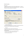
Adding a new connection
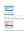
Step 1
Click on [Configure] tab
27
Step 2
Click on [Add] button
28
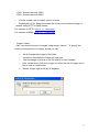
Step 3
A popup window should appear there will be many different types of
connection for you to choose from.
List of types of connections allowed.
RDP Connection
Internet Explore Connection
Citrix ICA Client
Dial-Up Connection
Ericom PowerTerm (for NE model only)
PPP over Ethernet (PPPoE)
Virtual Private Network (L2TPVPN)
Virtual Private Network (PPTPVPN)
Direct Connection
29
Creating a new ICA Client Connection
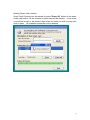
First select ICA client connections then the following window will popup.
Click on [Refresh] to search for available ICA server within the network.
Select the available ICA on the network and click on [Next]
Now you will be prompted to enter a name or tile for this connection.
Once you have decided on the name then click on [Next]
The next screen specifies an application will allow programs to be executed at
logon of a user. Use the file name as the command line and working directory
will be use to locate the file. You may choose to leave it blank and click on
[Next].
30
Now at the following screen you will be able to enter a set of user name and
password to enable automatic logon at connect. You may also choose to
leave this part black and click on [Next].
At this screen you will be able to manually configure settings to specify how the
application window will appear on the desktop. Select a color then click on
[Next]
31
Security configuration and sound will be a on the next screen.
Once settings
are properly configured, and then click on [Next].
This section is for advance users or administrator only, to configure the firewall
and proxy settings. If you are unsure what each field’s purpose and impact,
please contact your network administrator for help. For most networks you
can go ahead and click on [Done] leaving this section untouched.
32
Creating a new RDP Connection
RDP connection can be created by selecting the [Configure] tab then click on
[add].
33
A pop up window will allow you to choose [Microsoft Remote Desktop Client].
After RDP is selected the following screen will appear. Now you are ready to
key in a name for the connection and a host IP for the Thinclient to connect.
The automatically log onto screen will allow you to use a pre-configured client
and use that set of client to logon to the server every time when the connection
is made. You may also choose to leave this part blank and click on [Next] to
continue.
34
Upon connection, the Windows desktop is displayed by default.
To start an
application when you connect, select [Application file name] and specify an
application and its residing directory then click on [Next]. You may choose to
leave this part blank, and then by default user’s desktop will be at display upon
connection.
Click on [Next] to continue.
Now you are done with the connection and ready to connect.
35
Creating a Internet Explorer Connection
At the main screen first click on the [Configure] tab and select [Add] at the
lower left hand corner to create a new connection. After you click on add a
window should pop up asking what type of connection wish to be created.
Now you make select Microsoft Internet Explore and click on [OK].
Now you will be prompted to enter the connection name and the starting page
and an internet search engine. Once done entering all the information then
click on [New\Add] to continue.
36
Creating a Terminal Emulator
A terminal connection can be added by selecting the Ericom Power Term.
Connection properties will appear after OK was clicked. To make a
connection a host name must entered. The connection name at the very
bottom will be the connection at the main connection screen. In this case we
have NTUST as the connection name.
37
Creating a Dial-Up Connection
Dial-up connection page let you configure your Modem and dial up to a RAS
Server. The communication between the system and the clients is connected
through dial-up modem. First you will be prompted to key in the name of this
connection then click on [Next] to continue.
Select the serial port or modem to use. This field will depend on whichever
serial port modem is connected to. TCP/IP is important when using a dialup
connection. To establish connection properly, always remember to key-in
your DNS server IP address.
properly configured.
Click on [Next] once all the settings are
38
If you would like to change serial port settings or TCP/IP settings to the RAS
connection, click on “Configure or TCP/IP Settings” buttons respectively, and
within configure device properties you can adjust the Port Settings and the Call
Options to your standard requirement.
[Configure Modem] Properties
[TCP/IP] settings.
For advance dialup connection data can be encrypted. ThinClient provides
different types of encryption and these properties provide administrator or
users more security level choices to access ThinClient.
Phone number window allows area code and phone number to be entered.
39
Creating a Direct Connection
The communication between the server and the clients is connected through a
serial port. First users will be prompted to enter a name for this connection.
Once name is key in then click on [Next] to continue to the next page of setup.
The second step is to select the port used to communicate. Once again, the
serial port can be configured and TCP/IP can be given. For instructions on
configure the serial port, TCP/IP settings, and Security Settings, please refer to
page 36 of this manual.
40
Creating a Virtual Private Network Connection
The communication is connected through an established virtual channel
between the server and the client itself in the entire network. There are two
types of VPN. Please contact your Network Administrator if you are unsure
which one you should select.
Same as always, we must give a name to this connection and click on [Next].
Key in the host name or IP address of the server you wish to connect.
In order to have a proper connection, TCP/IP must be configured correctly.
The security settings maybe also configured.
41
Creating a PPPoE connection
PPPoE is mostly used to make connections with modern DSL. To create a
PPPoE connection, first at the main connection manager page and select
[Configure] tab from the top. Once you are in the configure screen, click on
[Add] to create a new connection.
The first step, same as always, this connection must be named.
For most PPPoE connection default is set to be PPPoe line 0. If you are
unsure which one to use, please contact your network administrator for help.
42
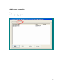
Configure an existing connection
You may edit the pre-made connection, by selecting the [Configure]. Once
you are in the configure tab select a connection name which needed to be
modify then click on [Edit].
Let’s use RDP connection for example.
The first option you are allowed to modify will be the [General] tab. Under
this tab you are allowed to change the connection name and the server IP
address. [Automatic Logon] may also be changed or leave untouched by
unselecting the Automatic logon box.
43
The numbers of color can be edited by selecting the second tab called
[Display]. Please note that the settings on the remote server might override
this setting.
[Local Resources] enables the remove server to use the resource from
ThinClient. One of the options is the sound option. Remote computer sound
can be either played at remote server or at the local ThinClient (if speaker is
connected). Second option allows disk mapping. All local devices such as
Disk drives, Printers, Serial ports, and Smart cards can be mapped to the
server and be used.
44
[Programs] tab, allows startup application be changed. The two options are:
On connect, desktop will be at displayed.
On connect, the specified program will be run. Please always remember to
specify the directory the program is located under.
The speed of connection can be modified on the [Experience] tab. The
amount of network bandwidth required is depended on the number of desktop
effect selected. More options selected will consume greater network
bandwidth.
45
Connecting to a server
To establish connection is simple on the ThinClient.
First select the
[Connections] tab on the Terminal Connection Manager and double click on a
pre-made connection to connect.
The list view allows the user to view and select connections for the purpose of
adding, editing, deleting, or specifying the startup behavior of a connection. If a
user double-clicks on a connection in the “Connection Name” column, the
effect is the same as selecting a connection and pressing the “Edit” button.
Highlighting a connection and pressing the Enter key also has the same effect
as double-click.
46
Auto Connecting
The Startup button allows the user to specify the startup behavior of a
connection. A connection’s startup behavior can be either “Default” or
“Autostart”. If a connection has been specified Default, it will be pre-selected
in the list view when the shell starts up so that the user need only press the
Enter key once to startup the connection. If the connection has been specified
as Autostart, the behavior is the same as specifying a connection as Default
with the one exception being that the shell will automatically start the
connection process instead of requiring that the user press the Enter key. If a
user does not select a Default connection, the first connection in the list will be
specified as the Default connection.
To enable Auto start on a pre-made connection:
1. Select the [Configure] Tab
2. Select a pre-made connection.
3. Click on [Startup..] and the following will appear
47
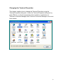
Changing the Terminal Properties
This chapter explains how to change the Terminal Properties using the
Terminal Properties dialog box. Invoke the Terminal Properties dialog box by
press “F2” key, or click the properties button located on right-bottom of
Terminal Connection Manager while Terminal Connection Manager is the most
front window.
48
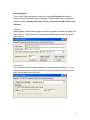
Internet Option
This Control Panel component opens the Internet Properties dialog box,
where Internet properties can be changed. These properties are organized
under five tabs: General, Security, Privacy, Connections, Advanced, and
Pop-ups.
General
Starting page, default search page and History cache can all be set under this
menu option. My Favorite link can also be disabled and enable under this
menu option.
Connection
The connection tab is mostly important for configure proxy settings. If your
network requires all out going connections to go through a proxy server first
then here is where you can set it.
49
Security
The security tab is where user configures the trusted sites and restricted sites
on Internet Explorer Browser. The additional ActiveX and plug-ins can be
found under the settings button.
Privacy
Privacy tab contain the cookie settings. This where cookies can be disabled if
needed.
50
Advanced
The advanced tab consists of Accessibility, Browsing, multimedia, Security.
you are new to Thinclient or you don’t understand the content at which it
contains you should leave this part alone.
If
Pop-ups
With pop-ups enabled all pop up window from a web site will be automatically
blocked.
51
Certificates
Allows you to manage certificates, trusted certificates can be imported or
deleted under this menu option.
Date/Time
The current time, date and time zone can be set under this menu option.
Daylight saving can be enabled here, to fit your time zone.
Dialing Properties
Dialing properties allows user to configure or add the “calling from” properties.
New calling origin can be added to make future dialing easier.
52
Display
There are two major functions under the display menu option. One is desktop
and the second one will be Screen Saver. For Detail information please refer
to below.
1. Desktop, allows you to change the desktop area and the refresh
frequency. Please note that for most standard LCD’s desktop area will be
at 1024 x 768. The default color will be True Color (32 bit).
Caution: be sure to click on test before you click on ok.
2. Screen Saver, enable and disable screen saver. Specifies the idle time
must elapse before the selected screen saver is displayed.
53
Ethernet Properties
The network properties tab will allow user to test and adjust network
connections. Within there are 2 tabs one is configuration tab and the other
will be network function tab. The detail of each will be explained at the
following.
1. Configuration, allows adjusting network adaptor’s duplex mode.
default it should be set at “auto detect”.
By
2. Network Function is made up by the ping command. Ping can be used,
whenever a user is in doubt of whether or not there is a network
connection.
In place, next to command, key in the IP address of the destination and
press ping to test. The result should be displayed at the status box.
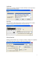
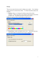
Firmware
Firmware Properties page allows you to upgrade firmware using a FTP server,
in which firmware is downloaded to ThinClient from your FTP server. You must
54
fill out the FTP server information and Login information in the Firmware
Properties page in order to start downloading the firmware image.
Notice: The upgrade process cannot be cancelled once you have started
upgrading.
ThinClient must be restarted for changes to take effect. The
created connection items remain no change and Terminal Properties are reset
to the factory defaults settings during the upgrade process.
Following are the steps for upgrading the firmware:
1. Click “Upgrade” button to start firmware downloading. After image download
finished, a dialog will popup for you to confirm update.
2. Fill in the server name and the server path that you are upgrading to and
click the upgrade icon.
3. To confirm upgrade firmware click “Yes” button on the dialog box or Click
“No” button to cancel upgrading.
4. Upgrade process completed.
5. Click “Reboot” button to restart the ThinClient
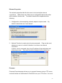
Global ICA Client Settings
55
ICA’s global client settings can be modified by this field. Some tools were
added to ensure a more user-friendly environment. Each of the additional
function will be explained in detail at the following section.
Keyboard Shortcuts
Hotkeys can be set by using Ctrl+number.
Preferences
At the preferences tab, users are allowed to specify at connect, the default
number of colors of their desktop, enable or disable PNAgent, and the serial
number of their local ThinClient.
The Program Neighborhood Agent allows users to connect without using a
Web browser to a server running the Web Interface and access all published
applications across multiple server farms. Users do not have to manually
configure a connection to each application as they do with Connection
Manager. The Program Neighborhood Agent also provides single sign-on:
56
when users log on at the start of a session, they do not have to supply their
logon credentials again during that session, even if they connect to several
different applications. You can update server URLs and configure ICA session
settings using the Program Neighborhood Agent, and you can also choose
which, if any, of these settings your users can access and modify.
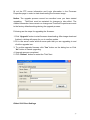
Server Location
The location of your ICA server can be specified or by automatic search. The
server location tab allows users to locate ICA servers and group them.
Firewall Settings
Proxy connection method, SSL/TLS relay and proxy server can all be setup
within the firewall settings. Contact your network administrator for detail
setup of your network.
57
Keyboard Properties
To adjust and configure the behavior of your keyboard
Line Printer
To enable Thinclient’s Line Printer, in another word is to use ThinClient as a
printer server. Any OS with UNIX printing protocol are allowed to use
ThinClient as a printer server.
Mouse Properties
Mouse Properties menu option allows adjusting the double click speed and
mouse movement of your ThinClient.
58
Network Settings
Adjust the network settings to fit your network.
contact your network administrator for help.
For detail setup please
Owner
There are 3 major functions or tab under this menu option. Identification,
Notes, Network ID, all plays important role in your network connectives.
Identification allows you to input your company information
Notes allow you to add any additional information which is not included
in the identification tab.
Network ID Windows CE uses this information to gain access to network
resources.
Regional and Language Settings
The Regional and Language allows user to customize to fit their language
needs.
59
Security
Security setting on the menu option protects your ThinClient from unauthorized
usage. You can put a password lock on your Thinclient at power on, resume of
screen saver, and properties (F2).
System Properties
System information can be obtained from the system properties menu option.
The following are the tabs within the system properties.
General This tab contains Operation System information and the
Processor type.
Product Product Name, Product ID (serial number), firmware version are
all part of this tab.
Memory Adjust the memories allocation of your ThinClient. When the
slider moves to the right then more memories is dedicated to programs.
When the slider moves to the left then more memories is dedicated to
storage.
Device Name Used to identify your ThinClient to other computers
(computer on the network).
About Displays the manufacture of your ThinClient.
60
Terminal Server Client Licenses
To view and manage the terminal client licenses that is stored on the
ThinClient. These licenses are normally issued by a server that Thinclient
connects to.
ThinPrint Client Configuration
The basic of ThinPrinter can be configured under this menu option.
61
Touch Panel Properties
Your ThinClient is compatible with few selected touch screens. The basic
configuration and type selection can be found under the Touch Panel
Properties. Once you have selected a touch screen and are ready to put it to
use make sure you always want to calibrate it before clicking on OK.
Virtual Desktop
Virtual Desktop allows network administers to monitor the actives on this
particular WinClient by VNC viewer. VNC (Virtual Network Computing)
Software makes it possible to view and fully-interact with one computer from
any other computer or mobile device anywhere on the Internet. VNC
software is cross-platform, allowing remote control between different types of
computer.
The virtual desktop is disabling by default.
62
Volume & Sound Properties
Your ThinClient is equipped with built in sound device. To configure the
loudness and default built in sounds, double click on the Volume & Sound
menu.
Wireless Properties
Your ThinClient equipped with wireless LAN capability.
wireless LAN will work with your ThinClient.
A few selected
TCP/IP Settings for Wireless LAN
Your wireless LAN TCP/IP setup is located under wireless LAN also in the
Network Setting icon under the F2.
63
Card Setup
Under the wireless menu and to the lower right you should see Card Setup.
This function is used to configure your wireless LAN settings. Within the Card
Setup there should be 2 sub menu or tabs. They are IP Information and
Wireless Information. For detail explanation of each function, refer to the
following and you can select the appropriate access point to for connecting.
IP Information displayed the current IP information of your wireless such as:
Address Type, IP Address, Subnet Mask and Default Gateway.
64
Wireless Information enable user to select a network to connect.
The main window will display the searched network, and user selects a
favorite one and press Connect button or right-click for more options like
encryption settings. To add a new network, double-click ‘Add New’.
This page consist of Connect, Advanced and View Log functions.
Connect: Press Connect when you select your favorite network.
Advanced: Windows will connect to the available networks; preference will be
given to networks at the top of this list.
View Log: List the wireless networking log.
65
Slave Smart Card for ThinClient
This chapter describes how to use the Smart Card on ThinClients which
support smart card features. Smart card reader has been built onto Thin Client
series and with its convenient function of “Mobile Connections” and advanced
security features, users are able to operate ThinClient anywhere by inserting
the smart card which is stored with their own connections. Such function is
specially designed for users who have to share thin-client with others.
Smart Card Features:
PIN number is encrypted to the smart card based on the DES (Data
Encryption Standard).
The smart card follows ISO-7816-4 standard
Flexible Mobile connections
More Security & More Convenient
How to Use the Slave Smart Card on Thin Client
Login with NEW Slave Smart Card
Pin number will need to be changed at the first usage of the smart card for
security reasons. Pin number can not exceed 8 characters by default the pin
number is “11111111”.
66
Change to a New Pin Number
You must type in the new digit that you wish to change to on the New Pin
Number column, and then re-type it to verify on the Confirm Pin Number
column. Both numbers must be identical or the system will provide you with the
following message.
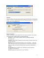
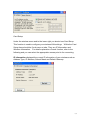
Using smart card on a ThinClient with existing connection
The original connection will be hidden on the ThinClient when smart card is
inserted on a ThinClient with residing connection.
The following method is for using a smart card with exiting connection on the
ThinClient.
Insert the smart card into Thin Client at POWER-ON state.
1. Please close all running sessions on ThinClient before the smart card is
inserted.
2. The color of the window of Connection Manager will turn gray. Then a
message saying “backup connections” will appear. This means ThinClient is
hiding the original connections
67
Original Connections
Process of hiding connection
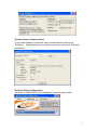
3. PIN Number authentication dialog box will popup after the original
connections is successfully hidden. Enter the default PIN Number to login
the system.
Notice: The smart card will be locked after three invalid entries. Contact
your administrator if the smart card is locked.
68
4. The connections of smart card will be loaded to system after passing the
authentication.
5. Users can now “Add”,”Edit”,”Delete” or “Connect”.
Using Smart Card at power on
Insert the smart card to Thin Client on POWER-OFF status.
1. Insert the smart card to Thin Client then power-on the system.
2. After passing the authentication, the connections of smart card will be
loaded to system.
3. Now you can add connections, delete connections, connect to a server by
using smart card.
Notice: The smart card will be locked after three invalid entries. Contact with
administrator if the smart card is locked.
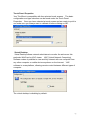
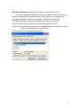
Terminal Smart Card Properties
There are three sections Smart Card Pin Number, Connections Information
and “Erase Smart Card Contents” in the smart card properties dialog box.
Smart Card Pin Number
Smart card Pin number function enables users to modify their pin number on
the smart card.
1. Into the Smart Card Pin Number section, enter the “New Pin Number” &
Retype “New Pin Number”.
2. Press the “Modify” button
3. Wait for Modify completed messages appear.
69
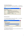
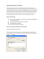
Connection Information
In the connections information section select the connections which you want
to save to smart card then click on save.
Notice: The “Total size” indicates the total size of the selected connections.
There are two kinds of smartcard supported, which are 8KB size and 16K size.
If your card is 8KB size, the total size can not exceed to 7KB; if your card is
16KB size, the total size can not exceed to 15KB.
For instance, if your card is 8KB size, and the total size, for example as follow
“14432”, has exceeded 7KB, the “Save” button will disabled, unselect the
connections and keep the total size within 7KB then save again.
After completed the save procedure, you can pull the smart card out of
ThinClient.
70
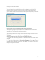
Erasing Smart card contents
Smart Card Contents can be erased by press “Erase All” button in the erase
smart card section. All the contents of smart card will be deleted. If only a few
connections is wish to be deleted, then select the ones you wish to keep then
click on save. All unwanted connection will be deleted.
71
BIOS Upgrade
This function is used to upgrade BIOS. To upgrade BIOS, follow the steps
below.
1 Connect USB floppy to WinClient and put the disk included BIOS image
file.
2 Power on WinClient.
3 When BIOS information appears, press “ALT+F2”, the upgrading utility will
be appears, and it will search BIOS image from USB floppy automatically.
If the image file is searched, the utility starts to upgrade BIOS.
4 After finishing to upgrade, the system will reboot automatically, press
“DEL” to enter BIOS menu when reboot. Go to “Load Optimized
Defaults” and enter “Y” to restore default settings, and press F10 to save
the settings and quit.
*Note: Do not remove USB floppy during upgrading progress.
Operation System Recovery
In TC620/820 series, you can recover operation system by using USB Disk or
USB CD-ROM.
Follow the steps to recovery your WinClient as below
1 Prepare recovery tool, USB Disk or USB CD-ROM, You can create those
recovery tools by WinClient Remote Manager. For more detail, please
refer to WinClient Remote Manager Guide.
2 Connect to WinClient.
3 Power on WinClient.
4 The utility will start to recover your WinClient automatically.
5 After finishing recovering, please remove recovery tool and reboot.
Note: The recovery speed can be enhanced by setting BIOS. Please follow
the steps as below:
1 Power on WinClient.
2 Press “DEL” to enter BIOS menu.
3 Go to Integrated Peripherals Î VIA OnChip PCI Device.
4 Set USB Ram Allocate to “Shadow”.
Note: Please restore this setting to “Ram Base” after finishing recovering.
72