1
Copyright
This manual and any accompanying software and firmware are copyrighted. No parts of
this publication may be reproduced, stored in a retrieval system, or transmitted, in any
form or by any means, electronic, mechanical, photocopy, recording, or otherwise,
without prior written consent except for copies retained by the purchaser for backup
purposes.
Trademarks
Product and company names mentioned in this manual are for identification purposes
only and may be trademarks of their respective companies.
Microsoft and Windows are registered trademarks of Microsoft Corporation.
ICA, MetaFtrame, WinFrame are registered trademarks of Citrix Systems, Inc.
Disclaimer
The information described in this manual is intended for instructional purposes only.
The Vendor reserves the right to revise this manual and all accompany software,
firmware without obligation to notify any person or organization of the revision or
change. The Vendor accepts no responsibility or liability for errors or misleading
information that may be contained in this manual.
Radio Frequency Interference Statement
FCC Statement
This equipment has been tested and found to comply with the limits for a Class B digital
device, pursuant to Part 15 of FCC Rules. These limits are designed to provide
reasonable protection against harmful interference when the equipment is operated in a
residential installation. This equipment generates, uses, and can radiate radio frequency
energy. if it is not installed and used in accordance with the instructions, may cause
harmful interference to radio communications. However, there is no guarantee that
interference will not occur in a particular installation. If this equipment does cause
harmful interference to radio or television reception, which can be determined by
turning the equipment off and on, the user is encouraged to try to correct the
interference by one or more of the following measures:
1
Reorient or relocate the receiving antenna.
Increase the separation between the equipment and receiver.
Connect the equipment into an outlet on a circuit different from that to which the
receiver is connected.
Consult the dealer or an experienced radio TV technician for help.
Notice:
The changes or modifications not expressly approved by the party responsible for
compliance could void the user's authority to operate the equipment.
IEC/EN Notice
This product conforms to the requirement of IEC950 and EN60950.
This product conforms to requirements of EN55022 for Class A equipment or EN55022
for Class B equipment.
2
End User License Agreement ("EULA") for MICROSOFT WINDOWS CE
OPERATING SYSTEM FOR WINDOWS-BASED TERMINAL DEVICES
VERSION 1.0
IMPORTANT-READ CAREFULLY:
This End User License Agreement (“EULA”) is a legal agreement
between you (either an individual or a single entity) and the manufacturer (“Manufacturer”) of the special purpose computing device
(“SYSTEM”) you acquired which includes certain Microsoft software product(s) installed on the SYSTEM and/or included in the
SYSTEM package (“SOFTWARE”). The SOFTWARE includes computer software, the associated media, any printed materials,
and any “online” or electronic documentation. By installing, copying downloading, or otherwise using the SOFTWARE, you agree
to be bound by the terms of this EULA. If you do not agree to the terms of this EULA, Manufacturer and Microsoft Licensing, Inc.
(“MS”) are unwilling to license the SOFTWARE to you. In such event, you may not use or copy the SOFTWARE, and you should
promptly contact Manufacturer for instructions on return of the unused product(s) for a refund.
SOFTWARE LICENSE
The SOFTWARE is protected by copyright laws and international copyright
treaties, as well as other intellectual property laws and treaties. The SOFTWARE
is licensed, not sold.
GRANT OF LICENSE. SOFTWARE includes software already installed on the
SYSTEM (“SYSTEM Software”) and, if included in the (Desktop Software”).
This EULA grants you the following rights to the SOFTWARE:
˙SYSTEM Software. You may use the SYSTEM Software only as installed in the
SYSTEM.
˙Desktop Software. Desktop Software might not be included with your SYSTEM. If
Desktop Software is included with your SYSTEM, you may install and use the
component(s) of the Desktop Software in accordance with the terms of the end
user license agreement provided with such component(s). In the absence of the
a separate end user license agreement for particular components(s) of the
Desktop Software, you may install and use only one (1) copy of such
component(s) on a single computer with which you use the SYSTEM.
˙Use of Windows CE Operating System for Windows-Based Terminal Devices with Microsoft
Windows NT Server, Terminal Sever Edition. If the SOFTWARE is Windows CE
operation system for Windows-Based Terminal devices, the following special
provisions apply. In order to use the SYSTEM in connection with Windows NT
Server, Terminal Server Edition, you must possess (1) a Client Access License
for Windows NT Server, Terminal Server Edition and (2) an end user license
for Windows NT Workstation or an end user license agreement for Windows
NT Workstation for Windows-Based Terminal Devices (please refer to the end
user license agreement for Windows NT Server, Terminal Sever Edition for
additional information). Manufacturer may have included a Certificate of
Authenticity for Windows NT Workstation for Windows-Based Terminal
Devices with the SYSTEM. In that case, this EULA constitutes an end user
3
license for the version of Windows NT Workstation for Window-Based
Terminal Devices indicated on such Certificate of Authenticity.
˙Back-up Copy. If Manufacturer has not included a back-up copy of the SYSTEM
Software with the SYSTEM, you may make a single back-up copy of the
SYSTEM Software. You may use the back-up copy solely for archival
purposes.
DESCRIPTION OF OTHER RIGHTS AND LIMITATIONS.
˙Speech/Handwriting Recognition. If the SYSTEM Software includes speech and/or
handwriting recognition component(s), you should understand that speech and
handwriting recognition are inherently statistical processes; that recognition
errors are inherent in the processes; that it is your responsibility to provide for
handling such errors and to monitor the recognition processes and correct any
errors. Neither manufacturer nor its suppliers shall be liable for any damages
arising out of errors in the speech and handwriting recognition processes.
˙Limitations on Reverse Engineering, Recompilation and Disassembly. You may not reverse
engineer, recompiles, or disassemble the SYSTEM Software, except and only to
the extent that such activity is expressly permitted by applicable law
notwithstanding this limitation.
˙Single SYSTEM. The SYSTEM Software is licensed with the SYSTEM as a single
integrated product. The SYSTEM Software installed in Read Only Memory
("ROM") of the SYSTEM may only be used as part of the SYSTEM.
˙Single EULA. The package for the SYSTEM Software may contain multiple
versions of this EULA, such as multiple translations and/or multiple media
versions (e.g., in the user documentation and in the software). Even if you
receive multiple versions of the EULA, you are licensed to use only one (1) copy
of the SYSTEM Software.
˙Rental. You may not rent or lease the SOFTWARE.
˙Software Transfer. You may permanently transfer all of your rights under this
EULA only as part of a sale or transfer of the SYSTEM, provided you retain
no copies, you transfer all of the SOFTWARE (including all component parts,
the media, any upgrades or backup copies, this EULA and, if applicable, the
Certificate(s) of Authenticity), and the recipient agrees to the terms of this
EULA. If the SOFTWARE is an upgrade, any transfer must include all prior
versions of the SOFTWARE.
˙Termination. Without prejudice to any other rights, Manufacturer or MS may
terminate this EULA if you fail to comply with the terms and conditions of the
EULA. In such event, you must destroy all copies of the SOFTWARE and all of
its component parts.
3. UPGRADES. If the SYSTEM Software and this EULA are provided separate
from the SYSTEM by Manufacturer and the SYSTEM Software is on a ROM
4
chip, CD ROM disk(s) or floppy disk(s), and labeled "For ROM Upgrade
Purpose Only" ("ROM Upgrade"), you may install one copy of the ROM
Upgrade onto the SYSTEM as a replacement copy for the SYSTEM Software
originally installed on the SYSTEM and use it in accordance with Section 1 of
this EULA.
4. COPYRIGHT. All title and copyrights in and to the SOFTWARE (including but
not limited to any images, photographs, animations, video, audio, music, text and
“applets,” incorporated into the SOFTWARE), the accompanying printed
materials, and any copies of the SOFTWARE, are owned by MS or its suppliers
(including Microsoft Corporation). You may not copy the printed materials
accompanying the SOFTWARE. All rights not specifically granted under this
EULA are reserved by MS and its suppliers (including Microsoft Corporation).
5. PRODUCT SUPPORT. Product support for the SOFTWARE is not provided by MS,
its parent corporation, Microsoft Corporation, or their affiliates or subsidiaries. For
product support, please refer to Manufacturer’s support number provided in the
documentation for the SYSTEM. Should you have any questions concerning this
EULA, or if you desire to contact Manufacturer for any other reason, please refer to
the address provided in the documentation for SYSTEM.
6. EXPORT RESTRICTIONS. You agree that you will no export or re-export the
SOFTWARE to any country, person, or entity subject to U.S. export restrictions.
You specifically agree no to export or re-export the SOFTWARE: (i) to any
country to which the U.S. has embargoed or restricted the export of goods or
services, which as of March 1998include, but are not necessarily limited to Cuba,
Iran, Iraq, Libya, North Korea, Sudan and Syria, or to any national of any such
country, wherever located, who intends to transmit or transport the products
back to such country; (ii) to any person or entity who you know or have reason to
know will utilize the SOFTWARE or potion thereof in the design, development
or production of nuclear, chemical or biological weapons; or (iii) to any person
or entity who has been prohibited from participating in U.S. export transactions
by any federal agency of the U.S. government.
If the SOFTWARE is labeled. “North America Only Version” above, on the
Products Identification Card, or on the SOFTWARE packaging or other written
materials, then the following applies: The SOFTWARE is intended for
distribution only in the United States, its territories and possessions (including
Puerto Rico, Guam, and U.S. Virgin Islands) and Canada. Export of the
SOFTWARE from the United States is regulated under “EI controls” of the E
xport Administration Regulations (EAR, 15 CFR 730-744) of the U.S. Commerce
Department, Bureau of Export Administration (BXA). A license is required to
export the SOFTWARE outside the United States or Canada. You agree that you
will not directly or indirectly, export or re-export the SOFTWARE (or portions
thereof) to any country, other than Canada, or to any person or entity subject to
U.S. export restrictions without first obtaining a Commerce Department Export
5
license. You warrant and represent that neither the BXA nor any other U.S.
federal agency has suspended, revoked or denied your export privileges.
7. NOTE ON JAVA SUPPORT. The SYSTEM Software may contain support for
programs written in Java. Java technology is not fault tolerant and is not
designed, manufactured, or intended for use or resale as on-line control
equipment in hazardous environments requiring fail-safe performance, such as
in the operation of nuclear facilities, aircraft navigation or communication
systems, air traffic control, direct lie support machines, or weapons systems, in
which the failure of Java technology could lead directly to death, personal injury,
or severe physical or environmental damage.
8. LIMITED WARRANTY.
˙Limited Warranty. Manufacturer warrants that the SOFTWARE will perform substantially in accordance
with the accompanying written materials for a period of ninety (90) days from the date of receipt. Any implied
warranties on the SOFTWARE are limited to ninety (90) days. Some states/jurisdictions do not allow
limitations on duration of an implied warranty, so the above limitation may not apply to you.
˙Customer Remedies. Manufacturer’s and its suppliers entire liability and your exclusive remedy shall
be, at Manufacturer’s option, either (a) return of the price paid, or (b) repair or replacement of the
SOFTWARE that does not meet the above Limited Warranty and which is returned to Manufacturer
with a copy of your receipt. This Limited Warranty is void if failure of the SOFTWARE has resulted
from accident, abuse, or misapplication. Any replacement SOFTWARE will be warranted for the
remainder for the original warranty period or thirty (30) days, whichever is longer.
˙No Other Warranties. EXCEPT AS EXPRESSLY PROVIDED IN THE LIMITED WARRANTY SECTION
ABOVE, THE SOFTWARE IS PROVIDED TO THE END USER “AS IS” WITHOUT WARRANTY OF
ANY KIND, EITHER EXPRESSED OR IMPLIED, INCLUDING, BUT NOT LIMITED TO, WARRANTIES
OF NON-INFRINGEMENT, MERCHANTABILITY, AND/OR FITNESS FOR A PARTICULAR PURPOSE.
THE ENTIRE RISK OF THE QUALITY AND PERFORMANCE OF THE SOFTWARE IS WITH YOU.
˙ No
Liability for Consequential Damages. MANUFACTURER OR MANUFACTURER’S SUPPLIERS,
INCLUDING MS AND ITS SUPPLIERS, SHALL NOT BE HELD TO ANY LIABILITY FOR ANY
DAMAGES SUFFERED OR INCURRED BY THE END USER (INCLUDING, BUT NOT LIMITED TO,
GENERAL, SPECIAL, CONSEQUENTIAL OR INCIDENTAL DAMAGES INFORMATION AND THE
LIKE), ARISING FROM OR IN CONNECTION WITH THE DELIVERY, USE OR PERFORMANCE OF
THE SOFTWARE.
If you acquired this EULA is the United States, this EULA is governed by the laws of the State of Washington.
If you acquired this EULA in Canada, this EULA is governed by the laws of the Province of Ontario, Canada.
Each of the parties hereto irrevocably attires to the jurisdiction of the courts of the Province of Ontario and
further agrees to commence any litigation which may arise hereunder in the courts located in the Judicial
District of York, Province of Ontario.
If this EULA was acquired outside the United States, then local law may apply.
Should you have any questions concerning this EULA, please contact the Manufacturer of your SYSTEMS.
U.S. GOVERNMENT RESTRICTED RIGHTS
The SOFTWARE and documentation are provided with RESTRICTED RIGHTS. Use, duplication, or disclosure by the
Government is subject to restrictions as set forth in subparagraph (c)(1)(ii) of the Rights in Technical Data and Computer
6
Software clause at DFARS 252.227-7013 or subparagraphs(c)(1) and (2) of the Commercial Computer Software—Restricted
Rights at 48 CFR 52.227-19, as applicable. Manufacturer is Microsoft Corporation/One Microsoft Way/Redmond, WA
98052-6399.
7
Contents
INTRODUCTION .....................................................................................10
INTRODUCING THE WINCLIENT.................................................................................... 10
FEATURES OF WINCLIENT TC320 SERIES ................................................................... 11
FEATURES OF WINCLIENT TC600 SERIES ................................................................... 12
FEATURES OF WINCLIENT TC805 SERIES ................................................................... 13
FEATURES OF WINCLIENT TC810 SERIES ................................................................... 14
HARDWARE SETUP ...............................................................................15
UNPACKING & CHECKING THE EQUIPMENT ................................................................. 15
IDENTIFY PARTS OF THE WINCLIENT TC320 ............................................................... 16
Front View .............................................................................................................. 16
Rear View ............................................................................................................... 17
IDENTIFY PARTS OF THE WINCLIENT TC600 ............................................................... 18
Front View .............................................................................................................. 18
Rear View ............................................................................................................... 19
IDENTIFY PARTS OF THE WINCLIENT TC805/TC810................................................... 20
Front View .............................................................................................................. 20
Rear View ............................................................................................................... 21
CONNECTING THE TERMINAL ....................................................................................... 22
USING THE POWER ON/OFF SWITCH ............................................................................ 22
START UP..................................................................................................23
QUICKLY CONFIGURE YOUR WINCLIENT .................................................................... 23
QUICKLY CONNECT YOUR WINCLIENT WITH SERVER ................................................. 29
Add new connection. .............................................................................................. 29
ICA Connection ...................................................................................................... 30
RDP Connection ..................................................................................................... 36
Internet Browser ..................................................................................................... 41
Terminal Emulator .................................................................................................. 43
Starting a connection .............................................................................................. 45
Stopping Connections ............................................................................................. 45
TERMINAL CONNECTIONS MANAGEMENT.................................46
USING THE CONNECTIONS PROPERTIES ........................................................................ 47
USING THE CONFIGURE PROPERTIES ............................................................................ 50
CHANGING THE TERMINAL PROPERTIES ...................................57
GENERAL PROPERTIES ................................................................................................. 57
8
Reset the Terminal to Factory Default Settings...................................................... 58
LOCAL RESOURCES PROPERTIES .................................................................................. 59
DISPLAY PROPERTIES ................................................................................................... 60
EXPERIENCE PROPERTIES ............................................................................................. 62
CONTROL PANEL.......................................................................................................... 63
Regional Settings Properties ................................................................................... 64
Network and Dial-Up Properties ............................................................................ 66
Printers Properties................................................................................................... 81
Keyboard Properties ............................................................................................... 85
System Properties ................................................................................................... 86
Mouse Properties .................................................................................................... 88
Volume and Sounds Properties............................................................................... 89
Date and Time Properties ....................................................................................... 90
FIRMWARE PROPERTIES ............................................................................................... 91
SECURITY PROPERTIES ................................................................................................. 92
MISCELLANEOUS PROPERTIES ..................................................................................... 94
ICA Global Setting: ................................................................................................ 94
Built-in Ethernet Duplex Mode: ............................................................................. 96
Touch Screen: ......................................................................................................... 97
Network Card Interface Settings............................................................................. 99
Ping Function ........................................................................................................ 101
SLAVE SMART CARD FOR WINCLIENT .......................................102
SMART CARD FEATURES:........................................................................................... 102
HOW TO USE THE SLAVE SMART CARD ON THIN CLIENT .......................................... 103
Login with NEW Slave Smart Card ..................................................................... 103
Change to a New Pin Number .............................................................................. 104
Backup the original connections to Disk on Chip ................................................ 105
Add and/or Edit Connections and Save Connections to Smart Card.................... 111
Change Smart card Pin Number ........................................................................... 117
9
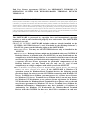
Introduction
Introducing the WinClient
WinClient Windows Based Terminals are designed to access any Windows application
such as Microsoft Word, Excel or PowerPoint residing on Windows Terminal Server.
WinClient is very easy on installation; there is no need to install any software onto
network. Simply plug a WinClient into the network, configure WinClient, and then
connect to Windows Terminal Server to run Windows applications.
WinClient supports RDP (Remote Desktop Protocol) and Citrix ICA (Independent
Computing Architecture). WinClient connects to one or more Windows NT-based
Servers via RDP & the Servers must be running Citrix MetaFrame or WinFrame to
capable with ICA.
10
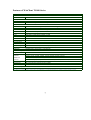
Features of WinClient TC320 Series
Model
Processor
TC-320N
TC-320NE
CPU
NS Geode 300MHz with 16KB unified Cache
NS Geode 300MHz with 16KB unified Cache
Memory
RAM
ROM
One SDRAM 168pin DIMM 64/128MB or above
One SDRAM 168pin DIMM 64/128MB or above
One Disk on chip flash ROM 8/16MB or above
One Disk on chip flash ROM 8/16MB or above
Up to 1024 * 768, 16bit high color, VESA monitor
support with DDC
10/100BaseT fast Ethernet, twisted pair RJ45
Up to 1024 * 768, 16bit high color, VESA monitor support
with DDC
10/100BaseT fast Ethernet, twisted pair RJ45
PS2 Type
RS232, 9Pin DSUB COM1, COM2
PS2 Type
RS232, 9Pin DSUB COM1, COM2
25Pin DSUB
25Pin DSUB
Standard Interface
VGA
LAN
Keyboard and Mouse
Serial
Parallel
USB Port
Audio Line Out
2 USB Ports
2 USB Ports
1/8inches mini, full 16bit stereo, 44KHz sample rate
1/8inches mini, full 16bit stereo, 44KHz sample rate
Power System
Connector
AC/DC Adapter
2 Pin Jack 5V DC.
2 Pin Jack 5V DC.
Input AC 100/240 Volt, 50~60Hz. Output 5VDC, 4A.
Input AC 100/240 Volt, 50~60Hz. Output 5VDC, 4A.
Physical Mechanical
Dimension
232 mm (H) x 42 mm (W) x 240 mm (D)
232 mm (H) x 42 mm (W) x 240 mm (D)
Client Side System Software
OS System
Terminal
Emulations
Microsoft Windows CE
Microsoft Windows CE
Local Browser
Microsoft – Internet Explorer (option)
Microsoft Remote Desktop Protocol RDP
IBM: AIXterm, 3270, 5250
Digital: VT42, VT100, VT220, VT320, VT420, VT520,
VT525
ANSI: ANSI-BBS, SCO-ANSI, AT386
Additional: Wyse (50/60), Data General D-412, Televido (TVI
925/950)
Microsoft – Internet Explorer (option)
Microsoft Remote Desktop Protocol RDP
Citrix ICA Protocol ICA
Local SNMP support
Citrix ICA Protocol ICA
Local SNMP support
Connectivity
SNMP
Server Side System Software
WinClient Remote Manager
WinClient Remote Manager
Wake on LAN
Wake on LAN
*Specification subject to change without notice, all trademarks or registered trademarks are properties of their respective owners
Management Tool
11
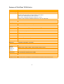
Features of WinClient TC600 Series
Model
TC-600 Thin Client
Processor
CPU
VIA Eden 533MHz or above
Memory
RAM
One SDRAM 144pin DIMM 64MB up to 512MB
DOC
One Disk on chip flash ROM 8MB up to 144MB
Standard Interface
VGA
up to 1024×768×32bit high color, VESA monitor support with DDC
LAN
One 10/100BaseT fast Ethernet port, twisted pair RJ45
PCMCIA
One IEEE802.11b Wireless LAN (Option)
Smart Card
One Smart Card (Option)
PS2
Support PS2 KB, Mouse
Serial
Two RS232, 9Pin DSUB COM1, COM2
Parallel
25Pin DSUB
USB Port
2 USB Ports
Audio Line Out
1/8inches mini, full 18bit stereo, 44KHz sample rate
Power System
Connector
2 Pin Jack 5V DC.
AC/DC Adapter
Input AC 100/240 Volt, 50~60Hz. Output 5VCD, 4A
Physical Mechanical
Dimension
220 mm (H) x 45 mm (W) x 155 mm (D)
Client Side System Software
OS System
Microsoft Windows CE
Optional
IBM: AIXterm, 3270, 5250
Terminal
Digital: VT42, VT100, VT220, VT320, VT420, VT520, VT525
Emulations
ANSI: ANSI-BBS, SCO-ANSI, AT386
(Option)
Additional: Wyse (50/60), Data General D-412, Televido (TVI 925/950)
Local Browser
Optional Microsoft Internet Explorer
Connectivity
Microsoft Remote Desktop Protocol RDP
Citrix ICA Protocol ICA
Server Side System Software
Management Tool WinClient Remote Manager
*Specification subject to change without notice, all trademarks or registered trademarks are properties of their respective owners.
12
Features of WinClient TC805 Series
Model
LCD
Panel Size / Type
OSD Control
TC-805 Thin Client
15”TFT Color LCD Panel
Auto-adjust
Monitor-control: H-position,V-position,Phase, Clock, Reset
OSD-control: OSD-H-position, OSD-V-position
Misc-control: Language, Information (firmware version)
Graphic-Control: Contrast, Brightness,Sharpness, Color, R, G & B Adj.
Processor
CPU
NS Geode 300MHz
Memory
RAM
One SDRAM 144pin SODIMM 64MB up to 512MB
DOC
One Disk on chip flash ROM 8MB up to 144MB
Standard Interface
VGA
up to 1024 × 768 16bit high colors, VESA monitor support with DDC
LAN
One 10/100BaseT fast Ethernet port, twisted pair RJ45
PCMCIA
One IEEE802.11b Wireless LAN (Option)
Smart Card
One Smart Card (Option)
PS2
Support PS2 KB, Mouse
Serial
One RS232, 9Pin DSUB COM1
Parallel
25Pin DSUB
USB Port
2 USB Ports
Audio Line Out
2 × 1 Watts speakers with Amplifier
Power System
Connector
2pin Jack 12V DC
AC/DC Adapter
Input AC 100/200 Volt, 50~60Hz, Output 12VDC 3.75A
Physical Mechanical
Dimension
331mm(H)×362mm(W)×175mm(D)
Client Side System Software
OS System
Microsoft Windows CE
Optional
IBM: AIXterm, 3270, 5250
Terminal
Digital: VT42, VT100, VT220, VT320, VT420, VT520, VT525
Emulations
ANSI: ANSI-BBS, SCO-ANSI, AT386
(Option)
Additional: Wyse (50/60), Data General D-412, Televido (TVI 925/950)
Local Browser
Optional
Connectivity
Microsoft Remote Desktop Protocol RDP
Citrix ICA Protocol ICA
Server Side System Software
Management Tool WinClient Remote Manager
*Specification subject to change without notice, all trademarks or registered trademarks are properties of their respective owners
13
Features of WinClient TC810 Series
Model
LCD
Panel Size / Type
OSD Control
TC-805 Thin Client
15”TFT Color LCD Panel
Auto-adjust
Monitor-control: H-position,V-position,Phase, Clock, Reset
OSD-control: OSD-H-position, OSD-V-position
Misc-control: Language, Information (firmware version)
Graphic-Control: Contrast, Brightness,Sharpness, Color, R, G & B Adj.
Processor
CPU
VIA Eden
Memory
RAM
One SDRAM 144pin SODIMM 64MB up to 512MB
DOC
One Disk on chip flash ROM 8MB up to 144MB
Standard Interface
VGA
up to 1024 × 768 16bit high colors, VESA monitor support with DDC
LAN
One 10/100BaseT fast Ethernet port, twisted pair RJ45
PCMCIA
One IEEE802.11b Wireless LAN (Option)
Smart Card
One Smart Card (Option)
PS2
Support PS2 KB, Mouse
Serial
One RS232, 9Pin DSUB COM1
Parallel
25Pin DSUB
USB Port
2 USB Ports
Audio Line Out
2 × 1 Watts speakers with Amplifier
Power System
Connector
2pin Jack 12V DC
AC/DC Adapter
Input AC 100/200 Volt, 50~60Hz, Output 12VDC 3.75A
Physical Mechanical
Dimension
331mm(H)×362mm(W)×175mm(D)
Client Side System Software
OS System
Microsoft Windows CE
Optional
IBM: AIXterm, 3270, 5250
Terminal
Digital: VT42, VT100, VT220, VT320, VT420, VT520, VT525
Emulations
ANSI: ANSI-BBS, SCO-ANSI, AT386
(Option)
Additional: Wyse (50/60), Data General D-412, Televido (TVI 925/950)
Local Browser
Optional
Connectivity
Microsoft Remote Desktop Protocol RDP
Citrix ICA Protocol ICA
Server Side System Software
Management Tool WinClient Remote Manager
*Specification subject to change without notice, all trademarks or registered trademarks are properties of their respective owners
14
Hardware Setup
Unpacking & Checking the Equipment
Before unpacking the WinClient, prepare a clean, stable surface to put the contents of
your WinClient shipping container on. You should find following items in the
WinClient package:
The WinClient TC320
One AC Adapter
A Power Cord
A Stand in three parts for your WinClient
User's Manual
*A PS/2 Keyboard with cable
*A PS/2 Mouse with cable
The WinClient TC600
One AC Adapter
A Power Cord
A Stand for your WinClient
User's Manual
*A PS/2 Keyboard with cable
*A PS/2 Mouse with cable
The WinClient TC805/TC810
One AC Adapter
A Power Cord
User's Manual
PS/2 Mouse, Keyboard spilt cable
*A PS/2 Keyboard with cable
*A PS/2 Mouse with cable
Notice:
*PS/2 Keyboard and Mouse are optional items.
15
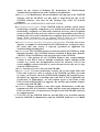
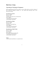
Identify Parts of the WinClient TC320
The illustrations that follow identify the various features of the WinClient TC320.
Front View
Network Activity
Indicator
Power Indicator
Power On/Off
Switch
Power On/Off Switch (The Power On/Off Switch turns your WinClient on or off. Push it in for on, out for off)
Network Activity Indicator (Yellow lights when your WinClient is sending data through a network)
Power Indicator (Green lights when your WinClient is connected to a power source and is turned on)
16
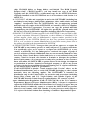
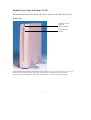
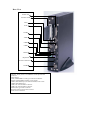
Rear View
TC-320 Series
Microphone
Headphone
Parallel
LAN
VGA
COM1
COM2
USB1
USB2
Keyboard
Mouse
Power Connector
Microphone, audio input.
Headphone, audio output for Headphones, Speaker.
Network , RJ-45 jack for a 10/100BaseT twisted pair Ethernet connector.
Video, standard DB-15 VGA type connector for Monitor.
Parallel, standard DB-25 parallel port for printer.
COM1, DB-9 RS232 port, for external modem, touch screen .
COM2, DB-9 RS232 port.
USB1, Universal Serial Bus connector.
USB2, Universal Serial Bus connector.
Mouse, PS/2 type mouse connector.
Keyboard, PS/2 type keyboard connector.
Power, Power Connector
17
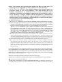
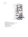
Identify Parts of the WinClient TC600
The illustrations that follow identify the various features of the WinClient TC600.
Front View
Network Activity
Indicator
Power Indicator
Power On/Off
Switch
Power On/Off Switch (The Power On/Off Switch turns your WinClient on or off. Push it in for on, out for off)
Network Activity Indicator (Yellow lights when your WinClient is sending data through a network)
Power Indicator (Green lights when your WinClient is connected to a power source and is turned on)
18
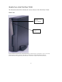
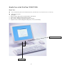
Rear View
Printer Port
Wireless LAN
LAN
VGA
COM2
Audio
USB1
USB2
Mouse
Keyboard
Power Connector
COM1
Network , RJ-45 jack for a 10/100BaseT twisted pair Ethernet
connector.
Audio output
Video, standard DB-15 VGA type connector for Monitor.
Parallel, standard DB-25 parallel port for printer.
COM1, DB-9 RS232 port, for external modem, touch screen .
COM2, DB-9 RS232 port.
USB1, Universal Serial Bus connector.
USB2, Universal Serial Bus connector.
Mouse, PS/2 type mouse connector.
Keyboard, PS/2 type keyboard connector.
Power, Power Connector
19
Identify Parts of the WinClient TC805/TC810
Front View
Power On/Off Switch (The Power On/Off Switch turns your WinClient on or off. Push it in for on, out for off)
OSD Functions include :
1.
2.
3.
4.
5.
Auto-adjust.
Monitor-control: H-position,V-position,Phase, Clock, Reset.
OSD-control: OSD-H-position, OSD-V-position.
Misc-control: Language, Information (firmware version)
Graphic-Control: Contrast, Brightness,Sharpness, Color, R, G & B Adj.
Power ON/OFF Switch
OSD Control
20
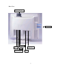
Rear View
Wireless LAN card
Smart Card
USB 1 & 2
Com 1
Printer Port
P/S 2
Power Connector
LAN
21
Connecting the Terminal
Before connecting the cables, arrange your WinClient and monitor in your work area.
Be sure not to block the vents around WinClient and Monitor.
Plug the AC power core into the power adapter, then into AC power source.
Connect the adapter cable to power connector
Connect the keyboard cable to keyboard connector.
Connect the mouse cable to mouse connector.
Connect the monitor video cable to video connector.
Connect the monitor power cable to the AC power source.
Connect the 10/100Base-T twisted pair network cable to network connector.
If you have a local printer, connect its cable to parallel port.
If you have microphone, plug its cable into microphone port.
If you have headphone or speaker, plug its cable into headphone port.
Using the Power On/Off Switch
After the cables are connected, you are ready to turn it on by pressing power On/Off
switch.
To turn on your WinClient, push the power On/Off switch in. The power indicator
lights.
To turn off your WinClient, push the power On/Off switch again so that it returns to
its extended position. The power indicator lights off.
Please note that the unit needs about 4-5 seconds of leading time when turning on or off.
So, once turn off the machine, to switch it on again, wait for 4 to 5 seconds, then switch
on.
22
START UP
Quickly Configure Your WinClient
After completing the hardware setup, the WinClient must be configured before it is
ready to use. This chapter guides you through the most easy and quick way to configure
your WinClinet. Quick configuring your WinClient can be accomplished through the
following steps:
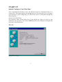
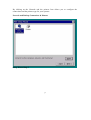
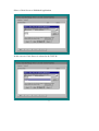
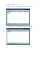
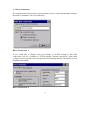
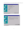
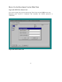
Power on your WinClient.
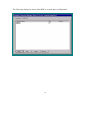
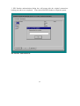
The Welcome setup wizard dialog box is first dialog box when you turn on your
terminal for the first time. Click on the [NEXT] button in the dialog box to display the
next setup wizard dialog box.
Welcome
Setup Wizard Step 1
23
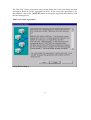
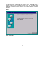
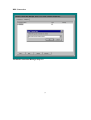
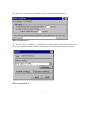
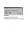
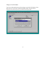
The End User License Agreement setup wizard dialog box is the next dialog box that
will appear. Read the license agreement carefully. If you accept this agreement to use
this terminal, click on the [ACCEPT] button to accept the agreement and continue with
the next setup process.
End User License Agreement
Setup Wizard Step 2
24
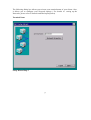
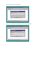
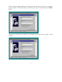
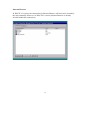
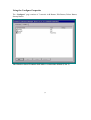
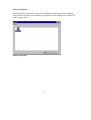
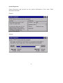
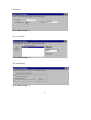
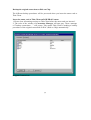
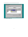
The following dialog box allows you to insert your terminal name of your clients. Also,
it allows you to configure your Network settings ( For details of setting up the
Networks, please refer to Network and Dial-up Properties) .
Terminal Name
Setup Wizard Step 3
25
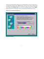
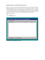
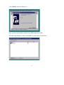
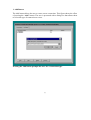
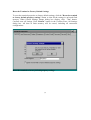
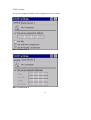
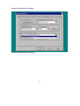
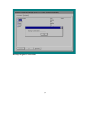
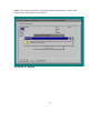
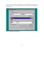
Desktop Area and Refresh Frequency setup wizard dialog box is the next dialog box. To
use the default resolution click [NEXT] button. You may choose other resolution from
the Desktop Area and Refresh frequency scroll list. To ensure your selection works with
your monitor, click [TEST] button. If you see the test image properly, click [NEXT]
button to go to the next dialog box, otherwise select other resolution and test again.
Desktop Area and Refresh Frequency
Setup Wizard Step 4
26
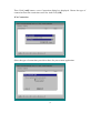
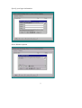
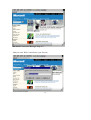
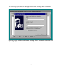
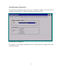
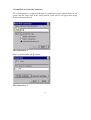
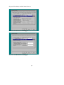
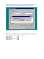
By clicking on the Network and the printers Icon allows you to configure the
connections and the printers type for your systems.
Network and Dial-up Connections & Printers
Setup Wizard Step 5
27
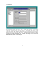
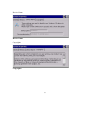
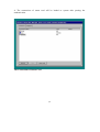
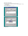
You have successfully completed the Setup Wizard. Click on the [FINSH] button to
apply the settings you have specified and exit Setup wizard. Any future change can be
made using the Terminal Properties dialog box. See the chapter Changing the Terminal
Properties.
Finish
Setup Wizard Step 6
28
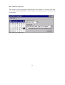
Quickly Connect your WinClient with Server
Now, you are ready to connect your WinClient with Server. The Terminal Connection
Manager dialog box will be displayed after the Setup Wizard closed. Terminal
Connection Manager will help you to manage your Terminal’s network connections.
See the Chapter Terminal Connections Management. This section guides you through
the most easy and quick way to connect your WinClinet with Server. Quick-Connecting
your WinClient on the network can be accomplished through following steps:
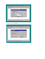
Add new connection.
Click [Configure] button
Terminal Connection Manager Step 1-1
29
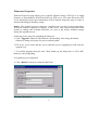
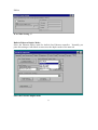
Then Click [Add] button, a new Connection dialog box displayed. Choose the type of
connection from the connection scroll list. And Click [OK].
ICA Connection
Select the type of connection you wish to have for your remote application.
30
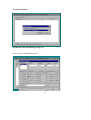
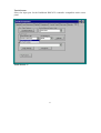
Select a Citrix Server or Published Application
In this case our Citrix Server is selected to be TEST2K
31
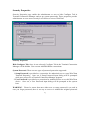
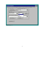
Put a title down for your ICA connection.
Specify your Command Line and Working Directory for your application.
32
Specify your logon information.
Select Window Options
33
Configure your Firewall Settings
34
ICA Client TEST2K now created.
The following dialog box shows when ICA is created under Connections.
The following dialog box shows when ICA is created under Configuration.
35
RDP Connection
Terminal Connection Manager Step 1-2
36
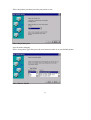
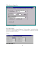
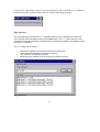
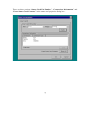
WTS Connection Wizard dialog box displayed. Enter the name of the new connection
into the “Name” field. Enter the server IP into the “Server” field. Click on [NEXT]
button.
In this case, we take server test2k as an example, type in the name “test2k” in both
columns.
37
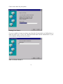
If you want to automatically log onto the server, click [Automatic Logon] and enter
your user name, password, and domain. Otherwise, you will be prompted for this
information each time you choose the connection. Click on [NEXT] button.
Using the default setting and click [NEXT] in the dialog box.
38
Click [Finish] button in dialog box
Now, you have successfully created a new RDP connection test2k.
The following dialog box shows when RDP is created under Connections.
39
The following dialog box shows when RDP is created under Configuration.
40
Internet Browser
In WinCE 3.0 version, the connection for Internet Browser will need to be created by
the users manually. However, in WinCE 4.0 version, Internet Browser is already
in-build within the connections.
41
Terminal Connection Manager Step 1-3
Add your own Web Connection to your favorite.
42
Terminal Emulator
Terminal Connection Manager Step 1-4
Select your Connection Properties
43
Type in your Terminal and Host name, in this case we selected “test” as our client.
Click on the ok icon to create your Power Term.
44
Starting a connection
Click [Connections] button.
Click the [Connection Name] in the list that you want to connect.
Click [Connect] button
Starting a Connection
Now, you are connected! Once you have started a connection, you can use programs
just as you would on a networked personal computer.
Stopping Connections
To stop connection, click-disconnect or logo-off from the windows start menu.
45
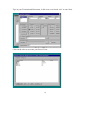
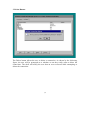
Terminal Connections Management
WinClient uses Terminal Connection Manager to manage connections with its server(s).
The Terminal Connection Manager dialog box displayed after Setup Wizard closed,
reboot or turn on WinClient in future. Terminal Connections Manager also can be
invoked at anytime during normal terminal operation by pressing the “Ctrl + Alt +
End”. Terminal Connection Manager dialog box consists of Connections and Configure
properties. The Connections properties provide the interface that users can start sessions,
switch among active sessions, and end sessions. The Configure properties also provide
the interface that users can add, modify, delete and startup connections.
The Windows-based Terminal shell with default conection
46
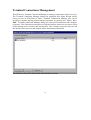
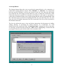
Using the Connections Properties
The Connections Properties page contains four controls: Connection Name List,
Connect Button, End Button and Power Off Button .
The Windows-based Terminal shell with 2 connections defined (AA and BB).
47
1. Connection Name List
After a connection is added, the name and the type of the connection will show in the
Connection Name List.
The Connection Name List allows user to view and select connections or end a
connection. If user double-clicks on a connection in the [Connection Name] column,
the effect is the same as selecting a connection and pressing the Connect button.
Highlighting a connection and pressing the Enter key also has the same effect as a
double-click.
2. Connect button
The Connect button is overloaded in terms of its functionality. If a connection is not
active, the button serves to activate the selected connection from the Name List. If a
connection is active, the button serves to switch between connections.
3. End button
The End button ends the connection process. When the user presses the “End” button,
the Terminal Connection Manager post a message to the client. If the connection is still
active after some specified amount of time (10 seconds by default), the user is given the
option of terminating the process as shown in figure.
The End Task dialog appears if a specified amount of time has passed and the
connection is still active after having pressed the End button.
48
The client should respond to the message and give user the opportunity to shut down the
connection. For example, in the case of RDP, the remote Window NT desktop comes to
the foreground and prompts the user as is shown by the following figure. The user will
only receive this message if they are logged in. If the session was simply waiting for a
user to login, the session will quietly exit.
The Microsoft RDP client responds to a WM_CLOSE message by prompting the
user as shown.
49
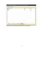
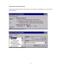
Using the Configure Properties
The “Configure” page consists of 5 controls: Add Button, Edit Button, Delete Button,
Startup Button.
The Windows-based Terminal shell with no connections defined (View 2)
50
1. Add Button
The Add button allows the user to create a new connection. This figure shows the effect
of pressing the “Add” button. The user is presented with a dialog box that allows them
to select the type of connection to create.
Pressing the Add button prompts the user for a connection type.
51
The following figure shows the dialog presented when selecting a RDP connection.
Selecting to add a “Microsoft Remote Desktop Client” connection starts the WTS
Connection Wizard.
52
2. Edit Button
The Edit button allows the user to edit or modify the properties of an existing
connection. Following figure shows the effect of pressing the Edit button for the
connection named “AA” which is a RDP connection (acronym for Microsoft Remote
Desktop Client). By pressing the “Edit” button, the shell starts the Edit Helper for RDP.
Selecting to edit the connection “AA” starts the Edit Helper for the “Microsoft
Remote Desktop Client” connection type.
53
3. Delete Button
The Delete button allows the user to delete a connection. As shown by the following
figure, the user will be prompted as to whether or not they really want to delete the
connection. The shell will notify the user that an error occurred while attempting to
delete the connection.
54
4. Startup Button
The Startup button allows the user to specify the startup behavior of a connection. A
connection’s startup behavior can be either “Default” or “Autostart”. If a connection
has been specified Default, it will be pre-selected in the list view when the shell starts
up so that the user need only press the Enter key once to startup the connection. If the
connection has been specified as Autostart, the behavior is the same as specifying a
connection as Default with the one exception being that the shell will automatically start
the connection process instead of requiring that the user press the Enter key. If a user
does not select a Default connection, the first connection in the list will be specified as
the Default connection.
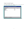
The list view allows the user to view and select connections for the purpose of adding,
editing, deleting, or specifying the startup behavior of a connection. If a user
double-clicks on a connection in the “Connection Name” column, the effect is the same
as selecting a connection and pressing the “Edit” button. Highlighting a connection and
pressing the Enter key also has the same effect as double-click.
Selecting a connection’s startup behavior
55
The connection “BB” with its startup behavior set to Auto-start.
56
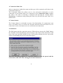
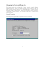
Changing the Terminal Properties
This chapter explains how to change the Terminal Properties using the Terminal
Properties dialog box. Invoke the Terminal Properties dialog box by press “F2” key
while Terminal Connection Manager is the most front window. Terminal Properties
dialog box consists of eight properties, General, Local Resources, Display, Experience,
Control Panel, Firmware, Security, and Miscellaneous that can be invoked by press
respective buttons.
General Properties
General Properties page describes the general information of WinClient.
General Properties
57
Reset the Terminal to Factory Default Settings
To reset the terminal properties to factory default settings, click the "Reset the terminal
to factory default property settings" button to clear all the settings in on-board flash
memory. When System Settings change dialog box display, click "Yes" button.
Confirm erase all settings Click “Reboot” button in the Confirm Erase All Settings
dialog box. All data in flash memory will be erased, including all connection
configurations.
Reset the terminal to factory default property settings
58
Local Resources Properties
Local Resources Properties page allows you to add and configure your local devices
including sound, disk drives, Printers, Serial Ports and Smart Cards .
Local Resources Properties
The default are set as Printers and Smart Card. To add local devices, simply click on the
items that you need.
59
Display Properties
Display Properties page let you configure your terminal’s display. The functions of
control buttons are as follow:
Desktop Area and Refresh Frequency: The Desktop Area Refresh Frequency
scrolling list displays current Terminal’s display resolution mode. You may choose
other resolution from the Desktop Area and Refresh frequency scroll list. To ensure
your selection works with your monitor, click “TEST” button.
Display Properties-1
60
If you see the test image properly then click “OK’ button, otherwise select other
resolution and test again.
Display Properties-2
Screen Saver: Set the Screen Saver enable or disable. When Screen Saver set enable,
select the display background and adjust the amount of elapse time to start the energy
saver
Colors: The Colors scrolling list displays current color depth. You may choose other
color depth from the Colors scroll list.
Click “OK” button to save changes and quit the Display Properties page. Click
“Cancel” button to quit the Display Properties without save changes.
Note:
Some of Terminal’s display resolutions and colors support by specific H/W platforms
only.
61
Experience Properties
Experience Properties page allows you to choose your own connection in order to
maximize your client’s connectivity performance.
Experience Properties
The connection allow the following configuration to be set-up :
1.
2.
3.
4.
5.
Desktop background
Show contents of window while dragging
Menu and window animation
Themes
Bitmap caching
62
Control Panel
Control Panel Properties is specially design for setting up the basic configuration of
your clients. It includes the following :
Control Panel Properties
1.
2.
3.
4.
5.
6.
7.
8.
Regional Settings
Network and Dial-up Properties
Printers
Keyboard
System
Mouse
Volume & Sounds
Date/Time
63
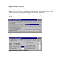
Regional Settings Properties
Regional Setting Properties allow you to change the locale and the user interface
language for your clients. It includes how numbers, dates, currencies and times and all
of these elements will change accordingly to your selected adjustments.
The Keyboard mapping and driver will be changed accordingly when you change the
Locale.
Regional Setting Properties
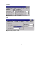
Number:
Regional Setting Properties- Number
64
Currency
Regional Setting Properties – Currency
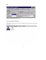
Time
Regional Setting Properties – Time
65
Date
Regional Setting Properties - Date
Network and Dial-Up Properties
This properties allows you to set up the configuration for your Network and Dial-up
connections.
66
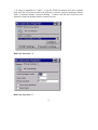
Dian Up Properties
Dial-Up Properties contain 3 different types of connections.
1. Dial-Up Connection
Dial-Up Connection page let you configure your Modem and dial up to a RAS Server.
The communication between the system and the clients is connected through dial-up
modem.
Dial-Up Connection -1
Setting up your Dial-Up connection, simply follow steps below to dial up to RAS server
when using a modem:
67
1.Select the serial port or modem to dial-in: Connect Hayes compatible modem to the
selected port.
Dial-Up Connection-2
2.If you would like to change TCP/IP settings to this RAS connection, click on
“Configure or TCP/IP Settings” buttons respectively. And within configure device
properties you can adjust the Port Settings and the Call Options to your standard
requirement..
Dial-Up Connection - 3
68
3. If “Hayes Compatible on COM1:” or specific PCMCIA modem card (if the optional
built-in PCMCIA slot has modem card inserted) is selected, input the telephone number
inside “Telephone Number” group for dialing. Country code and Area code have to be
inputted to make the dialing number formed correctly.
Dial-Up Connection – 4
Dial-Up Connection –5
69
TCP/IP settings :
Set up your assigned IP address and configuration of your clients.
Dial-Up Connection - 6
Dial-Up Connection - 7
70
Security Settings :
Security Properties page enable the administrator or user to hide Configure Tab in
Terminal Connection Manager and set up system passwords. These properties provide
administrator or users more security level choices to access WinClient.
Dial-Up Connection - 8
Enter your country, area code and phone number to complete set-up.
Dial-Up Connection - 9
71
2. Direct Connection
The communication between the systems and the clients is connected through serial port
then link to destination via LAN connection
Direct Connection -1
If you would like to change serial port settings or TCP/IP settings to this RAS
connection, click on “Configure or TCP/IP Settings” buttons respectively. And within
configure device properties you can adjust the Port Settings and the Call Options to your
standard requirement..
Direct Connection -2
72
Use the device properties to configure your port settings and call options.
Direct Connection -3
If “Serial Cable on COM1:” is selected, direct serial cable connection is assumed, in
this case, telephone number fields will be grayed. Click finish to complete the set-up.
Direct Connection -4
73
TCP/IP settings :
Set up your assigned IP address and configuration of your clients.
Direct Connection -5
Direct Connection -6
74
Security Settings :
Security Properties page enable the administrator or user to hide Configure Tab in
Terminal Connection Manager and set up system passwords. These properties provide
administrator or users more security level choices to access WinClient.
Direct Connection -7
75
3.Virtual Private Network Connection
The communication is connected through an established virtual channel between the
system and the client itself in the entire network. Date will be encrypted when being
transform between the two.
VPN Connection –1
Select your Host name and IP address.
VPN Connection –2
76
TCP/IP settings :
Set up your assigned IP address and configuration of your clients.
VPN Connection –3
VPN Connection –4
77
Security Settings :
Security Properties page enable the administrator or user to hide Configure Tab in
Terminal Connection Manager and set up system passwords. These properties provide
administrator or users more security level choices to access WinClient.
VPN Connection –5
78
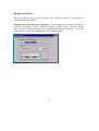
Network Properties
Network Properties page allows you to configure your network. The functions of
control buttons are as following:
IP Address
Network Properties –1
Obtain an Address from a DHCP server: Using this control button to gather IP
address and other settings from a DHCP server automatically.
Specify an IP Address: Using this control button to enter a specific IP address. Fill the
network information in the fields, if you don’t know the information, ask your network
administrators.
79
Name Servers: Using this control button to configure Name Servers settings. If “Name
Servers” control button is pressed, Name Servers settings dialog box displays. You can
set primary and secondary IP addresses for DNS server and primary and secondary IP
addresses for WINS server.
Network Properties –2
Click “OK” button to save changes and quit the Network Properties page. Click
“Cancel” button to quit the Network Properties without save changes.
80
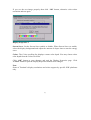
Printers Properties
Printer Properties support the local printer installation and network printer mapping.
Choose the local printer port and then press add printer will enable users to choose all
kind of printer driver.
Printer Properties
81
Select the printer port that you wish your printer to use.
Select the printer port
Network Printer Mapping
Select your printer type, then press the next button to make it as your default printer.
Select Printer Model
82
Create a user name for your printer
Naming Your Printer
If you are unable to locate an printer type from the list provided, use Defined box to
make an printer type of your own. Enter the model name and the manufacture of your
selected printer, then press the next button.
Make an Printer Model -1
83
The system will provide you an auto message of whether to configure another printer.
Make an Printer Model -2
Print Setup Finish -1
84
Print Setup Finish -2
You have now successfully configured your own printer.
Keyboard Properties
Keyboard Properties page allows you to set up the configuration of your keyboard.
Keyboard Properties
85
System Properties
System Properties page provide you the general information of the client. Those
information includes:
General :
general information
Memory
86
Device Name
Device Name
Copyrights
Copyrights
87
Mouse Properties
Mouse Properties page allows you to set up the configuration of your keyboard.
Mouse Properties -1
Mouse Properties -2
88
Volume and Sounds Properties
Volume and sound properties page allows you the make an adjustment on your client’s
sound qualities.
Volume and sound properties -1
Volume and sound properties -2
89
Date and Time Properties
This section is specially design for different time zone purpose, as one may have such
need for the time requirement. It will enable user to set up the time for the local
requirement.
Date and Time Properties
90
Firmware Properties
Firmware Properties page allows you to upgrade firmware using a FTP server, in which
firmware is downloaded to WinClient from your FTP server. You must fill out the FTP
server information and Login information in the Firmware Properties page in order to
start downloading the firmware image.
Notice: The upgrade process cannot be cancelled once you have started upgrading.
WinClient must be restarted for changes to take effect. The created connection items
remain no change and Terminal Properties are reset to the factory defaults settings
during the upgrade process.
Following are the steps for upgrading the firmware :
1. Click “Upgrade” button to start firmware downloading. After image download
finished, a dialog will popup for you to confirm update.
2. Fill in the server name and the server path that you are upgrading to and click the
upgrade icon.
3. To confirm upgrade firmware click “Yes” button on the dialog box or Click “No”
button to cancel upgrading.
4. Upgrade process completed.
5. Click “Reboot” button to restart the WinClient
Firmware Properties
91
Security Properties
Security Properties page enable the administrator or user to hide Configure Tab in
Terminal Connection Manager and set up system passwords. These properties provide
administrator or users more security level choices to access WinClient
Security Properties
Hide Configure Tab: Once it was selected, Configure Tab in the Terminal Connection
Manager will be hidden. User can not Add/Edit/Delete connections.
System Password: There are two types of password protection supported:
1. Setup Password is provided as a protection for authorized user to setup WinClient
Terminal Properties. Once set, a Setup Password input dialog will be prompted
while user presses F2 at Terminal Connection Manager program.
2. User Password is provided as a protection for authorized user to use this WinClient
device. Once set, a User Password input dialog will be prompted at the system
boot.
WARNING: Please be aware that once either user or setup password is set, and in
case you forget password, there is no way to recover it without the original password
92
except upgrading firmware image from boot ROM, please contact with your local
distributor in case you encounter this problem.
93
Miscellaneous Properties
Miscellaneous Properties
ICA Global Setting:
Note: Refer to Citrix ICA client for Windows CE Windows-Based Terminal User Guide
to set up ICA Global Settings. Under ICA Global Setting, users can adjust the following
functions according to their needs.
HotKeys
ICA Globe Setting –1
94
Preferences
ICA Globe Setting –2
Server Location
ICA Globe Setting –3
Firewall Settings
ICA Globe Setting –4
95
PNLite
ICA Globe Setting –5
Built-in Ethernet Duplex Mode:
Select the Ethernet duplex mode for built-in fast Ethernet controller. Normally you
place this setting at Auto Mode to auto sense the duplex mode of the network.
Select the Ethernet duplex mode
96
Touch Screen:
Select the input port for the PenMount DMC9512 controller compatible touch screen
panel.
Tauch Screen –1
97
Tauch Screen –2
98
Network Card Interface Settings.
Network Card Interface Settings -1
99
Set your IP Address and the Name Servers
Network Card Interface Settings -2
Network Card Interface Settings -3
100
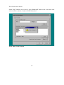
Click on the Card Setup icon to set up the wireless LAN card, however, if unable to
locate the card, the system will provide you with the following message.
Ping Function
The ping dialog box executes the ping diagnostic utility. Ping is a diagnostic tool that send
echo requests until interrupted by clicking on the Exit button. The ping utility sends one echo
request per second and calculates round trip times and packet loss statistics, and displays a brief
summary on completion.
The ping utility can be used to:
x
x
x
x
Determine the status of the network and various foreign hosts.
Track and isolate hardware and software problems.
Test, measure, and manage networks.
Determine the IP address of a host if only the hostname is known.
Ping Function
101
Slave Smart Card for WinClient
This chapter describes how to use the Smart Card on WinClients which support smart
card features. Smart card reader has been built onto Thin Client series and with its
convenient function of “Mobile Connections” and advanced security features, users are
able to operate Thin Client anywhere by inserting the smart card which is stored with
their own connections. Such function is specially designed for users who have to share
thin-client with others.
Smart Card Features:
PIN number is encrypted to the smart card based on the DES (Data
Encryption Standard).
The smart card follows ISO-7816-4 standard
Flexible Mobile connections
More Security & More Convenient
102
How to Use the Slave Smart Card on Thin Client
Login with NEW Slave Smart Card
User need to change the password when login Thin Client with the NEW smart card.
Password can’t exceed 8 characters and normally the default password is
“11111111”.
Login with NEW smart card
103
Change to a New Pin Number
Type the new digit number that you wish to change to on the New Pin Number column,
then re-type it to verify on the Confirm Pin Number column. They both must be
identical or the system will provide you with the following message.
104
Backup the original connections to Disk on Chip
The different backup procedures will be processed when you insert the smart card to
Thin Client.
Insert the smart card to Thin Client on POWER-ON status.
1: Please close all running sessions on Thin Client before the smart card was inserted .
2: The color of the window of Connection Manager will turn gray. Then a message
of ”backup connections….” will popup. This means Thin Client is making a backup
procedures of the original connections to DOC (Disk on Chip) automatically.
Original Connections
105
Backup Original Connections
106
3: PIN Number authentication dialog box will popup after the original connections
backup procedures are completed. Enter the default PIN Number to login the system.
Pin Number Authentication
107
Notice: The smart card will be locked after three invalid entries. Contact with
administrator if the smart card is locked.
Invalid Pin No. Remind
108
4: The connections of smart card will be loaded to system after passing the
authentication.
The Connections of Smart Card
109
5: Users can “Add”,”Edit”,”Delete” or “Connect” while the Connection Manager
appeared.
Insert the smart card to Thin Client on POWER-OFF status.
1: Insert the smart card to Thin Client then power-on the system.
2: After passing the authentication, the connections of smart card will be loaded to
system.
3: User can “Add”,”Edit”,”Delete” & “Connect” while the Connection Manager
appeared.
Notice: The smart card will be locked after three invalid entries. Contact with
administrator if the smart card is locked.
110
Add and/or Edit Connections and Save Connections to Smart Card
User can add new connections or edit existing connections then save connections to
smart card.
Add/Edit Connections
Users can add the connections & edit the connections in the Terminal Connection
Manger. Terminal Connections Manager can be invoked at anytime during normal
terminal operation by pressing the “Ctrl + Alt + End”. Refer to the Chapter Terminal
Connections Management for details.
Save Connections to smart card
Save connections to smart card can be accomplished through following steps.
1: Add and /or edit connections in Connection Manager,
2: Press “smart card” tab in the menu to enter Smart Card Properties.
Terminal Smart Card Properties
111
There are three sections “Smart Card Pin Number”, “Connections Information” and
“Erase Smart Card Contents” in the smart card properties dialog box. .
112
4. In the connections information section select the connections which you want to save
to smart card.
Select Connections
Notice: The “Total size” indicates the total size of the selected connections. Total size
can not exceed 7KB.
113
Press “Save” button to save the selected connections to smart card.
Save Connections to Smart Card
114
If The total size, for example as follow “8226”, has exceeded 7KB the warning message
will show on the screen, unselect the connections and keep the total size within 7KB
then save again.
Exceed 7KB Storage Size Warning
115
5. After completed the save procedure, you can pull the smart card out of Thin Client.
At this moment, the system will automatic restore to the original connections.
Restore Original Connections to DOC
Notice: The storage size of Smart card is limited to 7KB. So only 5~7 connections is
allowed on it, but it will also be depended on what kind of connections you wanted to
create. The size of connections are listed as following:
ICA connection:
RDP connection:
Power Term Connection:
Internet browser :
1,5KB
0.8KB
1.8KB
0.4KB
116
Change Smart card Pin Number
Smart Card Pin Number can be changed through following steps.
1. Into the Smart Card Pin Number section, enter the “New Pin Number” & Retype
“New Pin Number”.
2. Press the “Modify” button
3.Wait for Modify completed messages appear.
Change Password
117
Erase Smart card contents
Smart Card Contents can be erase by press “Erase All” button in the erase smart card
section. All the contents of smart card will be deleted.
Erase Smart Card Contents
118