1
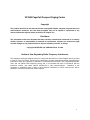
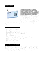
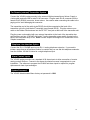
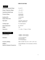
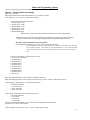
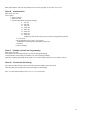
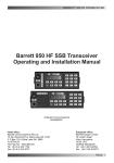
Visiplex, Inc.
VS1505/VS1800 PageCall Compact Paging
Center
User's Manual / Installation Guide
Version 1.3
VISIPLEX, INC. 2008
VS1800 PageCall Compact Paging Center
Copyright
The product described in this manual includes copyrighted Visiplex computer programs stored in
semiconductor memories. As such these programs may not be copied or reproduced in any
manner without the express written permission of Visiplex, Inc.
Disclaimer
The information within this document has been carefully checked and is believed to be entirely
reliable. However, no responsibility is assumed for inaccuracies. Visiplex, Inc. reserves the right
to make changes to any products herein to improve reliability, function, or design.
Copyright ©VISIPLEX, INC. VERNON HILLS, IL 2008
Notice to User Regarding Radio Frequency Interference
This equipment has been tested and found to comply with the limits for a Class B digital device, pursuant
to Part 15 of the FCC Rules. These limits are designed to provide reasonable protection against harmful
interference when the equipment is operated in a commercial environment. This equipment generates,
uses, and can radiate radio frequency energy and, if not installed and used in accordance with the
instruction manual, may cause harmful interference to radio communications. Operation of this
equipment in residential areas is likely to cause harmful interference in which case the user will be
required to correct the interference at their expense.
2
Table of Contents
INTRODUCTION
Standard Features of the VS1800
Optional Features of the VS1800
Encoder Options
Transceiver Options
Service Options
PROGRAMMING THE VS1800
GENERAL SCREEN INFORMATION
Page Menu
Send a Page
Page By Phone Option
MENUS AND PROGRAMMING MENUS
Menu A – Single Alarm Programming
Menu B – Administration Menu
Menu C – Multiple Alarm Point Programming
Menu D – Alarm Point Monitoring
Reset Database
PABX Demo Script
VS1800 TECHNICAL INFORMATION
Remote (external) Transmitter System
Telephone Line Interface Option
Alarm Contact Inputs
System Password
APPENDIX A
Transceiver Options
APPENDIX B
Service Options
SPECIFICATIONS
4
5
5
5
5
5
6
6
6
6
7
7
7
9
9
9
10
10
10
10
10
10
10
11
11
11
11
12-13
3
Introduction
The Visiplex VS1800 PageCall is a powerful
microprocessor based desktop paging system
capable of addressing 1000 pagers. It consists of a
fully featured encoder with a 2 line by 16-character
LCD display and a numeric keypad mounted in an
attractively styled housing and a 2-watt internal
transmitter. The VS1800 is capable of addressing
POCSAG, GOLAY, two-tone, 5/6 tone and tone
coded squelch signaling formats. The VS1800 is
compatible with the Visiplex series of transmitters
ranging from 2 to 200 watts. A 2 or 4-watt
transmitter can be installed internally at the factory.
Larger transmitters are accommodated on an
external (remote) basis. Non-Visiplex transmitters can also be used with the VS1800. Some
connect on a standard basis; others may require a local to tone control adapter (consult
Visiplex).
Standard Features of the VS1505
•
•
•
•
•
•
•
•
•
•
•
•
2 lines by 16 characters LCD display
Numeric keypad
Can page Alphanumeric and Numeric pagers
POCSAG, GOLAY, Two-Tone, 5/6 Tone signaling formats
512 or1200 baud rate selections for each POCSAG pager
Desk or wall mount
Single RJ-45, RS232 serial connection
96 dry contact or analog alarm point inputs with user programmable alphanumeric
messages using Windows™ based programming software
Built-in memory battery backup
1000 fully user configurable pager database
Built-in real time clock
1 year factory warranty
Optional Features of the VS1505
The VS1800 desktop encoder has extraordinary capabilities beyond the standard features.
These options may be classified in 3 basic categories. These are: Encoder, RF, and Service.
Each of these categories is listed below with the available features. In addition, customization is
possible (consult your Visiplex Sales Representative with your special requirements).
4
Encoder Options
•
•
•
•
•
•
•
•
•
An internal modem for Wide Area Paging and dial in remote access
A telephone line interface (RJ-11) for remote synthesized voice prompt and alarm input
status
A second RS-232 (RJ-45) serial port interface to enable Fire/Alarm, Nurse Call, and local
systems to interface with the VS1800
Input expansion modules (96 each)
Software interface for Audio/Visual Nurse Call Systems (Transitions interface/flash mode
input)
Synthesized voice prompt to enable voice alarm notification for two-way radios, voice
pagers, and telephones
Printed Reports Package
Transition Interface (Flash mode input for Audio Visual nurse call systems)
Event Controlled Relay Module to activate or deactivate electronic equipment
Transceiver Options
•
•
•
•
Internal 100mW Digital Transmitter
Internal 2-Watt Digital Transmitter
Internal 4-Watt Digital Transmitter
Remote high power 10-200 watt transmitters
For more information about radio transceiver, see also Appendix A.
Service Options:
•
•
Advance replacement service agreement
Person to Person Dedicated Technical Support
5
General Screen Information
The VS1800 menu screens that require data entry are made up of a series of visual prompts.
The prompt for each field appears on the top line of each screen.
Page Menu
The page menu appears soon after the VS1800 is turned on. The menu, shown below, is used
for sending a page to a pager or accessing the Programming and Administration Menus.
PAGE TO:
11:55
Enter a pager number to send a page
Press the corresponding letter key to advance to each of the Menus.
Send A Page
When entering the pager number, the leading zeros can be ignored. For instance, to page
pager #002, you can enter 002, 02 or 2. Any of the three will alert pager 002 in the database. If
the leading zeros are not entered, the # key must be entered after the pager number. After
entering the pager number, the next screen will automatically display:
ENTER MESSAGE:
_
If the pager is a numeric pager, you may enter up to a 16-digit numeric message now. A 16digit message will be sent automatically upon entering the 16th digit. If less than 16-digits are
entered, you must press the # key to send your message. If the pager is a tone only/vibrate
only pager, the page will be sent immediately after entering the pager number.
Page By Phone
If your VS1800 unit has the optional Page by Phone feature, the paging process is as follows:
1.
2.
3.
4.
5.
Call the VS1800 paging system analog extension from any standard touch-tone
telephone.
When the system answers you will hear the voice prompt “Enter Pager Number”. After the
voice prompt, enter the pager number.
If the pager type is numeric or alphanumeric, you will hear a second voice prompt “Enter
Message” The user may enter a numeric message using the telephone keypad. If this is a
tone only pager, you will hear “page sent” because no data entry is needed.
To end any message, press the # key or hang up.
After the page is sent, the system will prompt, “page sent”.
6
Menus and Programming Options
To access each menu, select the corresponding letter key on the keypad.
Menu A – Single Alarm Programming
Enter Password: 1500
Enter Input Number: Enter alarm point number 1-96 you wish to program.
Select Input type: (1-4) or (5-8)**, followed by the # key
1: Dry Contact, Normally Open (N.O.)
2: Dry Contact, Normally Closed (N.C)
3: Voltage, High – Low
4. Voltage, Low – High
5. Pulsing, High – Low
6. Pulsing, Low – High
7. Double Mode, Low
8. Double Mode, High
Double Mode – System will activate alarm on either pulse or steady voltage change.
*Alarm points 49-96 must have been originally requested upon system purchase (Option
VS1506)
** Options 5-8 must have been originally requested upon system purchase (Option VS1577)
IF USING VOLTAGE INPUT TYPE (3-8) ONLY:
Select threshold level: 000 (-24V) to 230 (+24V), followed by the # key
The threshold level can best be described as the voltage level at which
the system will sense a change in state. For example, if your threshold
level is +12V, once the voltage on the alarm point goes above or below
that level, the system will sense a change in state.
Select Activation Plan: 0-9, followed by the # key
1: Always Active (Default)
2: Schedule Plan 2
3: Schedule Plan 3
4: Schedule Plan 4
5: Schedule Plan 5
6: Schedule Plan 6
7: Schedule Plan 7
8: Schedule Plan 8
9: Schedule Plan 9
0: Non-Active
Enter three-digit pager ID to send alarm message to, followed by the # key.
Enter three-digit pager ID you wish to send a cancel message to (000 – No Page), followed by the #
key.
Select Number of Repeat Pages: 0-3, followed by the # key.
7
0: No Repeat (Default)
1: Up to Four Times
2: Up to Ten Times
3: Until Cancelled
Select Length of Input Delay: 0-3, followed by the # key.
0: No Delay (Default)
1: 10 Seconds
2: 30 Seconds
3: 120 Seconds
If using a VS1508 Relay Module, select which relay corresponds with the alarm point.
Press the # key to move to next option.
Update Changes? Press # key to save, or * key to escape without saving.
Enter Input Number: Enter the next alarm point you wish to program, or press the * key to exit.
Menu B – Administration Menu
Enter Password: 1500
Select Option:
1: Factory Settings
2: Enter new time
3: Com Port Baud Rates and Parity Settings*
1. 300, 7E1
2. 300, 8N1
3. 1200, 7E1
4. 1200, 8N1
5. 2400, 7E1
6. 2400, 8N1
7. 9600, 7E1
8. 9600, 8N1
*Change will affect both com ports, they cannot be programmed separately.
4 – 7: Not used
8: Reset All Data? Press # key to reset system.
WARNING: All alarm point programming will be lost!
9: Not used
0: Factory Settings
Menu C – Multiple Alarm Point Programming Menu
Enter Password: 1500
From Input: Enter alarm point number you wish to being programming
To Input Number: Enter alarm point number you wish to end programming
Input Type: Begin programming alarm points as you would a single alarm point, refer to Menu A above.
Menu D – Alarm Point Monitoring
The system will then show the status of the alarm point and voltage on the alarm point.
8
Once the alarm point is tripped, the status and voltage will both change.
Press * to enter different alarm point to view, or ** to exit menu D.
Resetting the Database
The Reset Database feature deletes all information stored in the VS1800 database, including all
pager information and all pre-programmed alarm messages.
Selecting <8> in the Administration menu will bring the next screen:
RESET DATABASE:
ARE YOU SURE?
If you are sure you want to reset the database, hit the #(pound) key to confirm. Any other key
will exit the Database Reset mode. After confirmation the unit screen will confirm that all system
data was cleared.
CAUTION: Selecting the Reset Database option deletes all system information. Do
not select this option unless you are sure you want to lose all information on
pagers as well as all preprogrammed messages. You may want to transcribe this
information to paper first, or use the optional PC software (page 14) to backup the
data to a computer.
PABX Demo Script
♦ Telephone Input With Voice Prompt Option allows access to the paging system from a touch
tone telephone. This feature works as follows: Dial the system PABX access code. This is a
special extension number assigned in a phone system for connecting to the VS1800 telephone
access port. You will hear the following voice prompts (or similar):
A. To send a numeric or voice message:
System:
Please enter pager number
User:
Enters three digit pager number
System:
Please enter message / Please wait & please speak message (if voice pager)
User:
Enters call back number . Press #(pound) or hang up to send the message.
Note:
If an invalid pager number is entered, the system voice will respond “Invalid
pager..” (or similar)
9
For Remote (external) Transmitter System
Connect the VS1800 paging encoder to the external Visiplex transmitter as follows: Supply a
4-wire cable terminated with a male RJ-45 connector. Plug the male RJ-45 connector into the
female RJ-45 (RS232) connector, shown above. Use caution when connecting the cable to the
paging unit to avoid damaging the connector.
The transmitter end of the cable (male DB-25) should be connected at the back of the
transmitter unit to the jack labeled Transmitter Input (female DB-25). Plug the antenna coax
cable or the Rubber Duck antenna into the RF-OUT coax jack at the back of the transmitter unit.
Plug the power cord supplied with your external transmitter to the back of the transmitter box
and the other end into a 120VAC wall outlet. Turn the transmitter power switch (located on the
back of the transmitter box) to ON. Note: Contact Visiplex tech support for connections to nonVisiplex transmitters.
Telephone Line Interface Option
Connect the RJ-11 PHONE input to your RJ-11 analog telephone extension. If you need to
initiate a page from an off premise location, be certain that you can dial this telephone extension
from the outside. VS1800 is limited to a single telephone input.
Alarm Contact Inputs
The VS1800 paging encoder has a standard of 96 alarm inputs to allow connection of remote
analog contact closures. Connect to the alarms by whatever means is appropriate for your
installation. The software to program the VS1800 and alarm inputs is required to program
alphanumeric alarm input messages.
System Password
The VS1800 Administration Menu factory set password is 1500.
10
Appendix A
Transceiver Options
♦ Internal 2-watt transmitter with rubber duck antenna (standard in VS1800)
♦ Internal 4-watt transmitter with rubber duck antenna (optional in VS1800).
♦ External Visiplex transmitters from 10-150 watts are available to meet most applications.
Certain hard to cover buildings or areas within a building may require the use of both low power
and high power transmitter(s) or multiple low power transmitters. Remote transmitters require
two twisted shielded pair between the VS1800 and transmitter. Use 22 or 24 gauge wire.
♦ Various antennae are avialable that are suitable for most applications. Fiberglass encased
antennas, mounted externally and connected to the transmitter provides paging coverage both
inside a building and for some distance away from the facility. How far (miles) that a system will
page depends on several things such as; antenna height, transmitter power and area
topography. These parameters and others combine to determine the paging coverage of a
system. Other antenna are designed for use within a building. The magnetic mount antenna,
for example, is the ideal cost effective way to extend paging coverage beyond that of the
standard rubber duck antenna within a building.
♦ Coaxial cable is used to connect the transmitter output to the antenna. The length of the
coaxial cable should be kept as short as possible to minimize the loss of signal. To keep power
losses to an absolute minimum, mount the transmitter as close to the outside antenna as
possible. Do not, for example, coil up 100 feet of coaxial cable to go 20 feet. One half of your
transmitter output power will be lost in 100 feet of coaxial cable. The type of coaxial cable
supplied by Visiplex is LMR-400. This is similar to, but of better quality (less loss) than RG-8U
coaxial cable.
Appendix B
Service Options
Visiplex systems are covered by a one year factory warranty. Factory warranty means repairs
will be performed at Visiplex. Warranty does not cover loss, physical, lightning, water damage,
etc. Since this is a factory warranty, the equipment must be sent to Visiplex for repair.
If this level of service is not satisfactory, Visiplex offers an Advanced Replacement program as
follows:
•
•
•
•
•
•
You need to purchase an Advanced Replacement Service Policy. (P.O. needed)
Separate P.O. for the repair of your defective system
Note: Parts are not covered under the Advanced Replacement Service Policy.
Visiplex will ship you (Overnight) an Advanced Replacement unit identical to the one in the field.
Ship us the defective unit. Visiplex will repair it and return it to you within 10 business days, if
possible.
You must return the Advanced Replacement unit to Visiplex within 30 days, otherwise you will
be invoiced for the full cost of the replacement unit.
♦ Pagers are covered by a factory one year parts, 120 days labor warranty unless the 3 year
extended warranty had been purchased at the same time as the pagers. Again, warranty or
extended warranty does not cover loss, physical or water damage, etc.
11
SPECIFICATIONS
General
Operating Temperature Range:
0 to +40° C
Storage Temperature Range:
-10 to +60° C
Operating Humidity Range:
10 to 65 %
Frequency Range:
403-433 MHz
438-470 MHz
Data Rate (RF):
512-2400 BPS
Speaker Audio Level:
500mW
Page Types:
Tone alert, Tone & Voice,
Numeric, Alphanumeric
Two-Way Types:
PL, Carrier-Squelch
Power Supply Input:
90 - 250 VAC
Weight:
2 lbs.
Dimensions:
7 ½” wide x 5” deep x 1¾” high
Internal Transmitter
RF Power Output:
VS1800-2 2.0 W minimum
VS1800-4 4.0 W minimum
Modulation:
± 3.5 kHz (data page)
± 5.0 kHz (voice)
± 3.5 kHz (tone page)
Frequency Stability:
Within ± 0.0025% from -30° to +60° C (+25° C ref.)
FM Noise:
At least 40dB below ± 3.0 kHz deviation at 1000 Hz
Spurious & Harmonic Frequencies:
75 db
12
RF Modules
RECEIVER, UHF:
Frequency Stability:
(30C to +60 C at +25 C reference)
+0.00025%
Sensitivity (12 dB SINAD):
0.35 µV max
Intermodulation (EIA SINAD):
70 dBm
Channel Spacing:
25 kHz
Adjacent Channel Selectivity (EIA):
70 dB
Modulation Acceptance:
+5.0 kHz, min.
Spurious Rejection:
EIA: 75 dB
CEPT: 70 dB
Image Rejection:
EIA: 60 dB
CEPT: 70 dB
Telephone
Input impedance:
Off-Hook
AC 600 ohm nominal
Telephone Audio:
DTMF Receive Level Dynamic Range: -26 dBm min.
DTMF Receive Frequencies Tone nominal +/- 1.5%
and +/- 2 Hz; 697,770,852,941,1209,1336,1477 and
1633.
Telephone Line Type:
Line level (end to end station level ) DTMF capability
FCC Registration Number:
GOX KS1000
13
VS1800 Quick Reference Programming Guide
14
Menus and Programming Options
To access each menu, select the corresponding letter key on the keypad
Menu A – Single Alarm Programming
Enter Password: 1500
Enter Input Number: Enter alarm point number 1-96 you wish to program.
Select Input type: (1-4) or (5-8)**, followed by the # key
2: Dry Contact, Normally Closed (N.C)
3: Voltage, High – Low
4. Voltage, Low – High
5. Pulsing, High – Low
6. Pulsing, Low – High
7. Double Mode, Low
8. Double Mode, High
Double Mode – System will activate alarm on either pulse or steady voltage change.
*Alarm points 49-96 must have been originally requested upon system purchase (Option VS1506)
** Options 5-8 must have been originally requested upon system purchase (Option VS1577)
IF USING VOLTAGE INPUT TYPE (3-8) ONLY:
Select threshold level: 000 (-24V) to 230 (+24V), followed by the # key
The threshold level can best be described as the voltage level at which the system will
sense a change in state. For example, if your threshold level is +12V, once the voltage
on the alarm point goes above or below that level, the system will sense a change in
state.
Select Activation Plan: 0-9, followed by the # key
1: Always Active (Default)
2: Schedule Plan 2
3: Schedule Plan 3
4: Schedule Plan 4
5: Schedule Plan 5
6: Schedule Plan 6
7: Schedule Plan 7
8: Schedule Plan 8
9: Schedule Plan 9
0: Non-Active
Enter three-digit pager ID to send message to, followed by the # key.
Enter three-digit pager ID you wish to send a cancel message to (000 – No Page), followed by the # key.
Select Number of Repeat Pages: 0-3, followed by the # key.
0: No Repeat (Default)
1: Up to Four Times
2: Up to Ten Times
3: Until Cancelled
Select Length of Input Delay: 0-3, followed by the # key.
0: No Delay (Default)
1: 10 Seconds
2: 30 Seconds
3: 120 Seconds
If using a VS1508 Relay Module, select which relay corresponds with the alarm point.
Press the # key to move to next option.
Update Changes? Press # key to save, or * key to escape without saving.
15
Enter Input Number: Enter the next alarm point you wish to program, or press the * key to exit.
Menu B – Administration
Enter Password: 1500
Select Option:
1: Factory Settings
2: Enter new time
3: Com Port Baud Rates and Parity Settings*
9. 300, 7E1
10. 300, 8N1
11. 1200, 7E1
12. 1200, 8N1
13. 2400, 7E1
14. 2400, 8N1
15. 9600, 7E1
16. 9600, 8N1
*Change will affect both com ports, they cannot be programmed separately.
4 – 7: Not used
8: Reset All Data? Press # key to reset system.
WARNING: All alarm point programming will be lost!
9: Not used
0: Factory Settings
Menu C – Multiple Alarm Point Programming
Enter Password: 1500
From Input: Enter alarm point number you wish to being programming
To Input Number: Enter alarm point number you wish to end programming
Input Type: Begin programming alarm points as you would a single alarm point, refer to Menu A above.
Menu D – Alarm Point Monitoring
The system will then show the status of the alarm point and voltage on the alarm point.
Once the alarm point is tripped, the status and voltage will both change.
Press * to enter different alarm point to view, or ** to exit menu D.
16