1
FlightMax EX500-Series
Instructions For Continued Airworthiness
A
VIDYNE
CORPORATION
55 Old Bedford Road
Lincoln, MA 01773
Document Number
AVMFD-083
Control Category
CC2
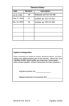
Revision
Description
ECO
Date
00
Initial Release
02-334
11/21/02
01
Change to incorporate FAA comment in
Section 16
02-355
12/06/02
02
Update to reference AML
03-054
2/06/03
Confidential property of Avidyne Corporation
Not to be disclosed without permission
FlightMax EX500-Series
Instructions For Continued Airworthiness
Table of Contents
1. Introduction...........................................................................4
1.1
Aircraft Description ......................................................................................................... 4
1.2
Scope.............................................................................................................................. 4
1.3
Applicability ..................................................................................................................... 4
1.4
Definitions and Abbreviations ......................................................................................... 4
1.5
Precautions ..................................................................................................................... 4
1.6
Units of Measure............................................................................................................. 4
1.7
Referenced Publications................................................................................................. 4
1.8
Distribution ...................................................................................................................... 4
2. Description ............................................................................5
3. Control and operation information ......................................5
4. Servicing information ...........................................................6
5. Maintenance instructions.....................................................6
5.1
Recommended periodic scheduled servicing tasks ....................................................... 6
5.2
Recommended periodic scheduled preventive maintenance tests/checks.................... 6
5.3
Recommended periodic scheduled inspections ............................................................. 6
5.4
Recommended periodic structural inspections............................................................... 6
6. Troubleshooting information ...............................................7
7. Removal and replacement information .............................11
7.1
Removal........................................................................................................................ 11
7.2
Installation..................................................................................................................... 11
7.3
System Setup and Checkout ........................................................................................ 11
8. Diagrams .............................................................................12
Confidential property of Avidyne Corporation
Not to be disclosed without permission
AVMFD-083
Revision :02 Date : 2/24/2003
Page 2 of 13
FlightMax EX500-Series
Instructions For Continued Airworthiness
9. Special inspection requirements .......................................12
10.
Application of protective treatments.............................12
11.
Data..................................................................................12
12.
List of special tools ........................................................12
13.
For commuter category aircraft.....................................12
14.
Recommended overhaul periods ..................................12
15.
Airworthiness limitation section....................................12
16.
Revision ..........................................................................12
Confidential property of Avidyne Corporation
Not to be disclosed without permission
AVMFD-083
Revision :02 Date : 2/24/2003
Page 3 of 13
FlightMax EX500-Series
Instructions For Continued Airworthiness
1. Introduction
1.1 Aircraft Description
Make:
Model:
Reference Avidyne 700-00007-XXX-() MFD Approved Model List
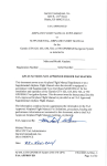
STC No. SA00161BO
1.2 Scope
This document identifies the Instructions For Continued Airworthiness (ICA) for the
modification of the above aircraft by installation of an Avidyne 700-00007-XXX-() EX500Series Multi-Function Display (MFD).
This ICA satisfies the requirements of 14 CFR 23.1529.
1.3 Applicability
This document applies to aircraft altered by the installation of an Avidyne 700-00007-XXX-()
FlightMax EX500-Series Multi-function Display (MFD).
1.4 Definitions and Abbreviations
ICA – Instructions for Continued Airworthiness
STC – Supplemental Type Certificate
MFD – Multi-function Display
AEG – Aircraft Evaluation Group
1.5 Precautions
This section not applicable.
1.6 Units of Measure
This section not applicable.
1.7 Referenced Publications
FlightMax EX500-Series MFD Installation Manual, P/N 600-00079-000
FlightMax EX500-Series MFD Pilot’s Guide, P/N 600-00078-000
1.8 Distribution
This Instructions For Continued Airworthiness is to be furnished with new production
EX500-Series MFD’s and is to become part of the permanent aircraft record upon installation.
A current revision of this ICA shall be available on the Avidyne website at
www.avidyne.com (Technical Publications in the Products section).
Confidential property of Avidyne Corporation
Not to be disclosed without permission
AVMFD-083
Revision :02 Date : 2/24/2003
Page 4 of 13
FlightMax EX500-Series
Instructions For Continued Airworthiness
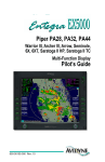
2. Description
The Avidyne 700-00007-XXX-() MFD is a radio rack mounted Multi-Function Display that
provides the following capabilities:
1.
A moving map display that provides terrain, geo-political boundaries, airspace,
navaids, airports, airways, and obstacles;
2.
Used with an external traffic detection system, it displays a pictorial representation
of nearby transponder-equipped aircraft overlaid on the moving map display;
3.
Used with an external lightning detection system, it presents a visual display of
lightning strikes or cells overlaid on the moving map display;
4.
Used with an external radar receiver/transmitter, it displays radar echo image data
on a radar display page, or overlaid on the moving map display;
5.
Used with an external Terrain Awareness Warning System, it displays EGPWS
terrain image data on a TAWS display page;
6.
Used with an external GPS navigator, it displays the current active flight plan
overlaid on the moving map display and in textual formats;
7. Using an internal digital data link transceiver, it displays strategic weather
information in graphical and textual formats.
3. Control and operation information
The Front Bezel serves as the physical interface to the pilot and consists of the following user
interface controls and display:
1.
Ten backlit line select keys;
2.
Variable function knobs, as discussed below;
3.
An LCD active matrix color graphics display;
4.
Display brightness control with backlit labeling;
5.
Power on-off pushbutton with backlit labeling;
6.
A USB port for performing nav database updates.
The system is equipped with two sets of concentric knobs; the two left knobs select bearing
line and radar tilt in Map, Radar, and TAWS pages, while the two right knobs select page and
range on Map, Radar, and TAWS pages, and page and line selection on other pages.
Complete operational details are provided in the referenced FlightMax EX500-Series MFD
Pilot’s Guide.
Confidential property of Avidyne Corporation
Not to be disclosed without permission
AVMFD-083
Revision :02 Date : 2/24/2003
Page 5 of 13
FlightMax EX500-Series
Instructions For Continued Airworthiness
4. Servicing information
This section is not applicable.
5. Maintenance instructions
Scheduled Maintenance Program tasks to be added to the aircraft operator’s appropriate
aircraft maintenance program are as follows:
5.1 Recommended periodic scheduled servicing tasks
The Avidyne EX500-Series MFD contains a 3-volt lithium battery that maintains CMOS
memory on an internal processor board and should be replaced after 10 years of service, or
when CMOS memory fails to retain configuration data, whichever occurs first. The Avidyne
EX500 must be returned to an authorized FAA repair station to perform this maintenance
function. Failure of the CMOS memory is indicated by the message “WARNING: CMOS
battery failure. Check database expiration date. Press any bezel key to continue” on a blue
background prior to system boot up. After system boot up, the MFD will function normally,
but will not have retained the system date and time. If the system is interfaced to the GNS
430 through ARINC 429, it will acquire current date and time from the GNS 430 when valid
data is received.
5.2 Recommended periodic scheduled preventive maintenance tests/checks
None required.
5.3 Recommended periodic scheduled inspections
None required.
5.4 Recommended periodic structural inspections
None required.
Confidential property of Avidyne Corporation
Not to be disclosed without permission
AVMFD-083
Revision :02 Date : 2/24/2003
Page 6 of 13
FlightMax EX500-Series
Instructions For Continued Airworthiness
6. Troubleshooting information
The Avidyne MFD incorporates a message bar located at the bottom of the display. Messages
are generated by the system and displayed on the message bar and are helpful in
troubleshooting system problems. Refer to Sensor manufacturer installation and users
manual to assist in troubleshooting. The following tables present the messages that are
generated by each application.
Table 1 – GPS/FMS Messages
Message
Meaning/Action
Nav Source Is Not Communicating
No RS 232 or ARINC 429 GPS data is being received.
Nav Source Data Is Not Valid
Data is being received from the external GPS. However, insufficient
information is available from the GPS to determine position.
o
Verify that the GPS has determined its “fix” or location
Nav Source Data Format Error
The MFD does not recognize the data being received from the GPS.
Nav Source Can’t Open Port (err=x)
The MFD is incorrectly setup with two devices on the same port.
Nav Source Reconnecting …
The data between the MFD and the GPS is being synchronized.
Heading Data Is Not Valid
When the GPS is being used as the heading source, heading data is
no longer available from the GPS.
o
Verify that the GPS has determined its “fix” or location.
Table 2 - Lightning Messages
Message
Lightning Sensor Error
Meaning/Action
The sensor system has reported an error.
o
Lightning Sensor Has Failed
The sensor system has reported an error.
o
Lightning Sensor Is Not Communicating
Verify that the sensor is turned on.
When the lightning sensor is being used as the heading source,
heading data is no longer available from the sensor.
o
Lightning –Antenna Location Changed
(Maintenance Mode)
Refer to lightning sensor user’s manual to troubleshoot.
Communication of strike data from the lightning sensor to the MFD
has been lost.
o
Lightning Heading Source Failed
Refer to lightning sensor user’s manual to troubleshoot.
Refer to lightning sensor user’s manual to troubleshoot.
Present when the antenna installation configuration between the
MFD and the WX500 is different.
Confidential property of Avidyne Corporation
Not to be disclosed without permission
AVMFD-083
Revision :02 Date : 2/24/2003
Page 7 of 13
FlightMax EX500-Series
Instructions For Continued Airworthiness
Table 3 - Traffic Messages
Message
Traffic Sensor Is Not Communicating
Meaning/Action
The traffic sensor is reporting a failure condition or not receiving valid
data.
o
TCAD Altitude Unavailable
{TCAD}
Traffic Sensor Heading Source Is Failed
{TCAS, TAS}
Refer to traffic system user’s manual to troubleshoot.
Altitude data is not being received by the traffic sensor.
o
Verify that the sensor is turned on.
o
Refer to traffic sensor user’s manual to troubleshoot.
When the traffic sensor is being used as the heading source, heading
data is no longer available from the sensor.
o
Refer to traffic sensor user’s manual to troubleshoot.
Table 4 - RADAR Messages
Message
Radar Sensor Data Is Invalid
Radar Sensor Has Failed
Meaning/Action
Data received from the RADAR sensor system can not be used by the
EX500
o
Cycle power on the EX500.
o
Refer to RADAR Sensor user’s manual to troubleshoot.
The RADAR sensor system has reported an error.
o
Radar Sensor Is Not Communicating
Communication of return data from the RADAR sensor to the MFD has
been lost.
o
Invalid GPS Data and Radar is ON
Radar Automatic Standby Disabled
Refer to RADAR Sensor user’s manual to troubleshoot.
Verify that the RADAR sensor is turned on.
The RADAR is ON and the EX500 has no ground speed data available
from the GPS/FMS.
o
Verify the GPS/FMS is ON.
o
Refer to RADAR Sensor user’s manual to troubleshoot.
The RADAR is ON, the EX500 RADAR automatic standby mode is
disabled, and the EX500 has no ground speed data available from the
GPS/FMS.
Confidential property of Avidyne Corporation
Not to be disclosed without permission
AVMFD-083
Revision :02 Date : 2/24/2003
Page 8 of 13
FlightMax EX500-Series
Instructions For Continued Airworthiness
Table 5 - TAWS Messages
Message
TAWS Display Failed
Meaning/Action
An incorrect system configuration or failure in one of the system
components has occurred.
o
TAWS Display Initializing
TAWS Not Communicating
TAWS Display Unavailable
TAWS Sensor Self-Test
TAWS Display Inhibited
Verify that the sensor is turned on.
If message does not clear within 60 seconds, communication
between the EX500 and the terrain sensor has not been established.
o
Verify that the sensor is turned on.
o
Refer to terrain sensor user’s manual to troubleshoot.
Indicates that the EX500 is not receiving data from the terrain sensor.
o
Verify that the sensor is turned on.
o
Refer to TAWS sensor user’s manual to troubleshoot.
The TAWS Sensor has declared itself inoperative.
o
Verify that the sensor inputs to the TAWS are turned on.
o
Refer to TAWS sensor user’s manual to troubleshoot.
The TAWS Sensor is performing a Self-Test. The message will
remain until the self-test is finished.
o
Verify that the “INHIBIT” mode has been not been selected at
the separate TAWS control panel.
o
Refer to TAWS sensor user’s manual to troubleshoot.
The TAWS sensor is in the “Self-Test” mode.
o
Verify that the “Self-Test” mode has been not been selected
at the separate TAWS control panel.
o
Refer to TAWS sensor user’s manual to troubleshoot.
Confidential property of Avidyne Corporation
Not to be disclosed without permission
AVMFD-083
Revision :02 Date : 2/24/2003
Page 9 of 13
FlightMax EX500-Series
Instructions For Continued Airworthiness
Table 6 - Datalink Messages
Message
Meaning/Action
Datalink Sensor Data Is Invalid
The EX500 has received unreadable satellite data.
Datalink Sensor Configuration Error
The EX500 is improperly configured for datalink.
o
Datalink Sensor Is NOT Communicating
Requires factory servicing. Refer to Factory Service Policies
section of this manual.
The EX500 is experiencing a communication failure with the internal
Satellite transceiver.
o
Requires factory servicing. Refer to Factory Service Policies
section of this manual.
Table 7 - Heading Messages
Message
Synchro Heading is NOT Valid
Meaning/Action
The EX500 not receiving or is receiving bad heading synchro data.
Upon loss of unit functionality post-installation, the following post-flight actions may be
taken:
i. Perform post-installation checkout procedures in accordance with the procedures
contained with in the FlightMax EX500-Series MFD Installation Manual,
ii. Perform installation checkout or self-test procedures for sensors (EGPWS, RADAR,
etc.) interfaced to the EX500,
iii. Contact Avidyne for return authorization and instructions. Contact information is
available at www.avidyne.com.
Confidential property of Avidyne Corporation
Not to be disclosed without permission
AVMFD-083
Revision :02 Date : 2/24/2003
Page 10 of 13
FlightMax EX500-Series
Instructions For Continued Airworthiness
7. Removal and replacement information
Removal and replacement instructions, including system set-up and installation verification,
are contained in the referenced FlightMax EX500-Series MFD Installation Manual. Unit
removal, installation, setup and checkout should be performed by an Avidyne Authorized
Service Center. A current list of authorized centers may be found on the Web at
www.avidyne.com.
7.1 Removal
To remove the EX500 MFD from the radio rack, loosening the unit locking key with 3/32”
Allen wrench having a minimum length of 3.5 inches. With power off the system, pull the
unit from its rack.
7.2 Installation
With power off the system, insert the EX500 MFD into the radio rack tray and tighten the
locking key with a 3/32” Allen wrench having a minimum length of 3.5 inches.
Upon reinstallation, a functional check should be performed in accordance with the System
Setup and Checkout procedures detailed in Section 7.3
7.3 System Setup and Checkout
Any time the Avidyne MFD is removed and sent to the factory for service, or is replaced with
another unit, these system setup procedures should be performed to assure that the unit is
properly configured for the installation. System set-up and installation verification
procedures are contained in the FlightMax EX500-Series MFD Installation Manual.
Confidential property of Avidyne Corporation
Not to be disclosed without permission
AVMFD-083
Revision :02 Date : 2/24/2003
Page 11 of 13
FlightMax EX500-Series
Instructions For Continued Airworthiness
8. Diagrams
This section is not applicable.
9. Special inspection requirements
This section is not applicable.
10. Application of protective treatments
This section is not applicable.
11. Data
This section is not applicable.
12. List of special tools
A size 3/32” Allen wrench, with a minimum length of 3.5 inches, is required to loosen the
tray locking mechanism.
13. For commuter category aircraft
This section is not applicable.
14. Recommended overhaul periods
This section is not applicable.
15. Airworthiness limitation section
The Airworthiness Limitations section is FAA approved and specifies maintenance required
under §43.16 and §91.403 of the Federal Aviation Regulations unless an alternative program
has been FAA approved.
There are no additional airworthiness limitations as a result of this modification.
16. Revision
Revisions to this document shall be coordinated through the Boston Aircraft Certification
Office, the Kansas City AEG, and the STC holder. Inquiries relating to the ICA should be
made to Avidyne Corporation. If you would like to be notified of future revisions to this
manual please furnish the information listed below:
Name
Address
City, State, and Zip Code
Part Number of Manual
Current Revision Status of Manual
Please submit this information to:
Avidyne Corporation
55 Old Bedford Road
Lincoln, MA 01773
Confidential property of Avidyne Corporation
Not to be disclosed without permission
AVMFD-083
Revision :02 Date : 2/24/2003
Page 12 of 13
FlightMax EX500-Series
Instructions For Continued Airworthiness
Confidential property of Avidyne Corporation
Not to be disclosed without permission
AVMFD-083
Revision :02 Date : 2/24/2003
Page 13 of 13