1
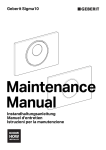
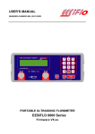
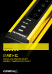
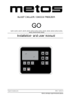
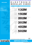
B L A S T
C H I L L E R S
E5-14 / E5-20
E10-35
E14-40 / E14-65 / E14.2-70
INSTRUCTION MANUAL
Cod. 71503788/0 - 06/2009 - Rev. 00
WA R N I N G ! ! !
GB
THE FOLLOWING OPERATIONS AND
THOSE HIGHLIGHTED BY THIS SYMBOL
MUST NOT BE PERFORMED BY THE
APPLIANCE USER
1.
2.
WATER CONNECTIONS
4.
TESTING
6.
DISASSEMBLY OF THE APPLIANCE AND/OR ITS COMPONENTS
3.
5.
7.
8.
32
ELECTRICAL CONNECTIONS
INSTALLATION
REPAIRING MACHINE COMPONENTS
ADJUSTMENTS AND CALIBRATION
CLEANING THE APPLIANCE AND MAINTENANCE OF:
- ELECTRICAL PARTS,
- ELECTRONIC PARTS,
- MECHANICAL PARTS,
- REFRIGERATION SYSTEM PARTS
GB
CONTENTS
1.
1.1
1.2
1.3
1.4
1.5
GENERAL DOCUMENTATION
General information
Installation
Transport and handling
Unpacking - disposal of packaging materials
General safety regulations
page
page
page
page
page
5
5
5
5
6
2.
2.1
2.2
2.3
2.4
2.5
2.6
2.7
2.8
2.9
INSTALLATION
Data plate information
page
Positioning
page
Ambient temperature and air circulation
page
Electrical connections
page
Refrigeration component connections - remote assemblies page
Condensate drainage connection
page
Information for the installation technician
page
Safety and control systems
page
Appliance disposal
page
6
6
7
7
7
7
7
8
8
3.
3.1
3.2
3.2.1
3.2.2
ADVICE TO ENSURE EFFICIENT APPLIANCE OPERATION
Shut-down procedures
page
Operating tips
page
Precooling
page
Loading the appliance
page
9
9
9
9
4.
4.1
DESCRIPTION OF THE CONTROL PANEL
Push-buttons
page
page
10
11
5.
5.1
5.2
5.3
PROGRAMMING AND OPERATING INSTRUCTIONS
Starting up the appliance
Soft blast chilling by temperature
Soft timed blast chilling
Hard blast chilling
Hard blast chilling by temperature
Hard timed blast chilling
Blast freezing by temperature
Timed blast freezing
page
page
page
page
page
page
page
page
12
12
14
14
14
15
16
17
5.4
5.5
5.6
5.7
33
GB
34
6
6.1
6.2
6.3
6.4
6.5
6.6
6.7
6.8
6.9
6.10
APPLIANCE FUNCTIONS
Date and time settings
Ice cream surface hardening
Muting the beeper and alarm reset
Program storage
Displaying the three latest HACCP alarms
Printing out stored data
Forced ventilation function
User programming
Manual defrosting
Automatic defrost cycles
page
page
page
page
page
page
page
page
page
page
18
18
18
18
18
18
19
19
19
19
7.
7.1
7.2
ALARM MANAGEMENT
Storage of data/errors
Alarms list
page
page
20
20
8.
8.1
8.2
8.3
8.4
MAINTENANCE AND CLEANING
General safety regulations
Cleaning the condenser
Cleaning the cell
Defrost water drainage
page
page
page
page
22
22
23
24
1. GENERAL DOCUMENTATION
1.1. General information
• This manual is an integral part of the
product, providing all the information
required to ensure correct installation,
operation and maintenance of the
machine.
• Read the manual carefully, making reference to it for machine operation. Keep
the manual in a safe place where it can
be accessed by all authorised operators
(installers, operators and service personnel).
The machine has been constructed in
compliance
with
the
directives
73/23/CEE (low-voltage), 89/336/CEE
(electromagnetic compatibility) and
98/37/CE (machines; for certain models
only).
• The machine has been designed for professional applications only and should
only be operated by qualified personnel.
• The machine must only be used for the
purposes for which it was designed, i.e.
for chilling and freezing food products.
The machine must not be used for products requiring constant temperature control and recording, such as:
- heat-sensitive chemicals,
- medicines or
- blood products.
• The manufacturer declines all responsibility for any damage caused by incorrect or
unreasonable machine use, such as:
• improper use by untrained persons;
• technical modifications or operations
not suited to specific models;
• use of non-original or non-specific
spare parts;
• failure to follow the instructions given in
this manual.
This appliance is not intended for use by persons -including children- with reduced physical, sensory or mental capabilities, or lack of
experience and knowledge, unless they
have been fiven superfision or instruction
concerning use of the appliance by a person
responsible for their safeti. Children should
GB
I
be supervised to ensure that they do not play
with appliance.
1.2 Installation
The machine must be installed by a specialised technician authorised by and in
compliance with the instructions given in
this manual.
In the event that the machine is fitted with
a remote condenser unit, the installation
technician is responsible for checking all
connections in compliance with the
instructions given by for plant and machine
installation.
1.3 Transport and handling
• To load or unload the machine and/or
components from/onto the means of
transport, use a lift truck or fork lift
equipped with forks that are at least half
the length of the machine housing; use a
crane if the machine is fitted with eye
bolts. Select the lifting equipment suited
to the weight and overall dimensions of
the packaged machine/components.
• When handling the machine/ components,
apply all precautions to prevent damage,
in compliance with the information given
on the packaging material (fig. 1).
1.4 Unpacking
• Remove all cardboard, wood or other
materials from the wood base on which
the machine is set. Lift the
machine/components with suitable
means (e.g. lift truck), remove the wood
base,
then
position
the
machine/components in the allocated
35
GB
site.
• Once all packing
material has been
removed,
check
that the machine
has not been damaged in any way.
• Remove the protective PVC film on
the stainless steel
panels from all internal and external surfaces (fig. 2).
• Always wear protective gloves when
handling packing material and the
wood base.
• NB Dispose of packing materials in compliance with disposal regulations applied
in the country where the machine is to be
installed. Never dispose of materials in
the environment.
1.5 General safety regulations
Failure to observe the recommendations
made by the present manual will be at the
entire responsibility of the machine user.
The main safety regulations are as follows:
- do not touch the machine with moist
or wet hands or feet;
- never operate the machine while barefoot;
- do not insert screwdrivers, cooking
utensils or any other object between
the guards and moving parts;
- before performing cleaning or routine
maintenance operations, disconnect
the machine from the power supply at
the master switch and the main knife
switch (if present);
- never pull on the power cable to disconnect the machine from the power
supply.
WA R N I N G ! ! !
THESE OPERATIONS MUST BE
PERFORMED BY A CERTIFIED INSTALLATION
TECHNICIAN ONLY.
2. INSTALLATION
2.1
Data plate information
• Check that the data specified on the
plate correspond to the characteristics
of the power supply (V, kW, Hz, no. phases and power available).
• The dataplate with appliance specifications is located at the rear exterior of the
machine and/or
on the electrical
boards (fig. 3).
The set-up
of
individual
units and the
installation of condensers are subject to
the fire-safety regulations of the country
in which the machine is installed; seek all
necessary advice from the local firefighting authorities.
Bear in mind that the intervention of safety valves or plug fuses in the refrigerat36
ing circuit will lead to the immediate discharge of refrigerant into the environment.
2.2
Positioning
• The machine must be installed and commissioned in complete compliance with
safety regulations, procedures and
standing laws.
• The installation technician bears the
responsibility of ensuring compliance
with fire safety requirements; seek all
necessary advice from the local firefighting authorities.
• Position the machine in the allocated
site.
• Adjust the machine feet until the appliance is perfectly level. In the case of
particularly heavy equipment, use
appropriate lifting means
GB
(fig. 1).
• If the appliance is not perfectly level, correct operation and condensate flow-off
will not be assured.
AVOID
• direct exposure to sunlight;
• closed sites with high temperatures and
poor air circulation;
• installing the machine near sources of
heat (fig. 4).
Electrical connections
2.4
A dedicated thermal-magnetic circuit
breaker compliant with established regulations must be installed on the appliance
power line.
• Connected electrical cables must correspond to the technical data (as specified
on electrical drawings provided by the
installation technician).
Connect the earthing conductor to an efficient earthing system.
THE MANUFACTURER DECLINES ALL
LIABILITY AND GUARANTEE OBLIGATIONS IN THE EVENT OF INJURY TO
PERSONS OR DAMAGE TO EQUIPMENT AND OBJECTS DUE TO INCORRECT INSTALLATION AND/OR FAILURE
TO COMPLY WITH STANDING INSTALLATION REGULATIONS.
CONNECTING THE APPLIANCE
TO THE POWER SUPPLY.
In the event of damage to the power supply cable on the appliance, have the cable
replaced only by a qualified electrician to
avoid any risk of personal injury.
2.5
2.3
Ambient temperature and air circulation
For air-cooled appliances, the maximum
ambient temperature for operation is 32°C.
Correct operation cannot be guaranteed at
higher temperatures.
The machine may operate safely to a maximum temperature of 38°C.
Remote condensing units must be
installed in special rooms or outdoors, protected against direct sunlight by a shelter
or roof structure (at the cost of the purchaser).
Sufficient air circulation must be guaranteed at all times.
Refrigeration component
connections - remote assemblies
Appliance power lines are sized for installation distances of up to 10 metres. For
greater distances, seek advice from .
2.6
Condensate drainage connection
Fit a condensate/wash water drainage
hose with a minimum diameter of 1”
(“Geberit” or similar type).
Provide a waste pipe
with a trap with a diameter of at least 1 1/2” at
floor level.
37
GB
Information for the installation
technician
Before starting up the machine, check that
it has been correctly installed and commissioned (test report).
1. Check that there are no gas leaks from
weldings or joints made during installation works.
2. Check that the pipes connecting the
condenser to the remote condensing
unit have been well insulated.
3. Check all wiring connections.
4. Check electrical input.
5. Check the standard pressure in the
refrigerant system.
6. Check the water connections and efficiency of the pressure switch valve during operation, as well as the flow of condensing water (in water-cooled units).
7. Perform at least one blast freezing cycle
(to the SET temperature) and one manual defrosting cycle.
In the event that the appliance or the
remote condensing unit have not been
transported in a vertical position (e.g. on
the back) or have been overturned during
installation works, allow at least 4 hours
before starting up the equipment.
2.7
• Inform the customer of the exact purpose
of the appliance, with specific reference
to the use and requirements of the customer.
The appliance must be installed and put
into service by a technician authorised.
2.8
Safety and control systems
• Door microswitch: shuts down fan operation in the cell when the door is opened.
• General fuses: protect the power circuit
against short circuiting and overloads.
• Compressor heat relay: intervenes in the
event of overloads or operating faults.
• Safety pressure switch: intervenes in the
event of excessive pressure in the refrigerant circuit.
38
• Plug fuses: intervene in the event of overpressure or operating fault in the safety
pressure switch (see above).
• Chamber temperature control: operated
by the electronic board by means of a
probe inside the cell.
• Temperature control end defrost cycle:
controlled by the electronic board by
means of the probe in the evaporator.
2.9
Disposal of waste electronic
and electrical equipment (WEEE)
Fulfilling
Directives
2002/95/CE,
2002/96/CE and 2003/108/CE on the disposal of waste electronic and electrical
equipment.
The crossed out wheeled bin symbol indicates the product must be
collected separately from other
waste when it has become redundant. Differentiated collection of
this equipment is arranged and
handled by themanufacturer.
Consequently, the user who is wanting to
dispose of this equipment must contact the
manufacturer and follow the method the latter has adopted to allow separate collection
of the redundant equipment.
Appropriate differentiated collection for the
subsequent recycling, treatment and ecofriendly disposal of the dismantled equipment prevents possible negative effects on
the environment and health and facilitates
the recycling of materials used in manufacturing the equipment.
Administrative sanctions foreseen by the
regulations in force shall be applied for any
abusive disposal of the product by the holder.
3. ADVICE TO ENSURE EFFICIENT APPLIANCE OPERATION
GB
3.1
Shut-down procedures
In the event of emergency, shut down the
appliance by switching off power at the
main panel, by means of the knife switch or
by removing the plug from the power socket.
3.2
Operating tips
Before starting up the appliance, clean the
inside of the cell thoroughly.
3.2.1 Pre-cooling
Before using the appliance for the first
time, or after a prolonged period of disuse,
pre-cool the cell by running an empty
cycle until the set operating temperature
has been reached.
To ensure optimal performance without any
alteration to food quality: arrange food
products in such a way as to favour the circulation of cold air throughout the cell;
open the door
as little as possible.
3.2.2 Loading the appliance
a) Ensure that foods to be chilled and/or
frozen are separate and do not have a
thickness greater than 50-80 mm. Do
not load the appliance beyond the
quantity recommended by the manufacturer.
b) Ensure that there is sufficient clearance
between trays to enable free air circulation.
If the appliance is not completely full,
distribute the trays and foods evenly
throughout the available space.
0.5 - 2cm.
c) Position trays inside the tray compartment as far as they will go, as close as
possible to the evaporator.
d) Position the core probe at the centre of
the largest product or food item; make
sure that the tip of the probe does not
protrude or touch the tray.
The probe must be cleaned and sanitised before each new cycle (operation)
to prevent inadvertent contamination.
e) Avoid covering the trays and/or containers with insulating covers or film. The
more the product is insulated, the more
time is required for chilling or freezing.
Trays must be packaged when the product has been chilled, before being
placed in storage.
39
4. DESCRIPTION OF THE VERTICAL CONTROL PANEL
GB
3
2
5a
4
5b
5
6
16
15
7
1
8
13
14
40
11
9
10
12
4.1
PUSH-BUTTONS :
1.
ON /OFF (STAND BY)
2.
2
SOFT BLAST CHILLING CYCLE (+3 °C)
3.
HARD BLAST CHILLING CYCLE (+3°C)
4.
BLAST FREEZING CYCLE (-18°C)
5.
END CYCLE BY TIME / PROBE (TEMPERATURE)
5A.
PROBE CHILLING INDICATOR LED
5B.
TIMED CHILLING INDICATOR LED
6.
CYCLE START / STOP
7.
INCREASE VALUE
8.
DECREASE VALUE
9.
RECIPE PROGRAMS (CHILLING CYCLES)
10.
HACCP AND PRINTER (OPTIONAL)
11.
STERILIZATION BY UV-C LAMP (OPTIONAL)
12.
DEFROSTING / FORCED VENTILATION
13.
CHILLING / FREEZING CYCLE INDICATOR LED
14.
STORAGE INDICATOR LED
15.
TIME DISPLAY
16.
TEMPERATURE DISPLAY
GB
41
GB
5. PROGRAMMING AND OPERATING INSTRUCTIONS
I M P O R TA N T ! ! !
IN THE EVENT OF MALFUNCTION, SEEK THE
ASSISTANCE OF A CERTIFIED TECHNICIAN
Delayed start of compressor during first starting
(for models E14-40 / E14-65 / E14.2-70)
Pre-heating function of compressor sump
When the board is reached by mins tension, a 2-hour pre-heating phase starts and the display
shows some blinking dashes “---”. During this phase the machine cannot be started.
NOTE
The delayed start takes place only if the machine is given power by its dedicated magnetothermic switch.
It is therefore advisable that, after first starting, the machineis started or stopped by using the
control panel pushbutton. This way, the compressor pre-heating function is guaranteed, and the
machine starting takes place in a direct way.
Initial pre-heating is necessary in order to safeguard the compressor’s life. Only if strictly necessary (and under the customer’s responsability) it is possible to by-pass countdown by pressing
the pushbutton “printer/HACCP” for about 5 seconds
This function is not activated if machine stops/starts operating due to lack of power
during working cicle.
5.1
STARTING UP THE APPLIANCE
When the appliance is powered up, it can be:
• ON displays 15
LED 1
and 16
and left LED 5A
on push-button 5
on,
off
• OFF-STAND-BY LED on push-button 1
on
To switch from one status to another, press push-button 1
.
Whenever the appliance switches from STAND-BY status to ON, a self-test is carried out: all
LEDs and displays are switched on, push-buttons are checked, then the installed software version is displayed.
OPERATION
The main work cycles (chilling/freezing) performed by the appliance:
• SOFT BLAST CHILLING (+3°C)
Pre-cooked food is rapidly chilled (90’) to a temperature of +3°C, thus preventing proliferation of bacteria and preventing dehydration of the cooked food due to evaporation. Food can
thus be stored perfectly for 5 to 7 days without altering its original qualities.
• HARD BLAST CHILLING (+3°C)
This process is designed to cool food products with a thickness greater than 2-3 cm. Variable
air temperatures are used to accelerate penetration of cold into the product.
42
GB
• BLAST FREEZING (-18°C)
This function freezes the product completely to a temperature of -18°C in less than 4 hours.
The rapidity of the process prevents formation of macrocrystals essential to ensure that the
product retains its original consistency and quality when thawed for consumption.
• AUTOMATIC CONSERVATION
At the end of each cycle (chilling or freezing), the appliance will automatically switch to the
required storage temperature.
Two different end-cycle modes are available for each cycle:
• BY TEMPERATURE - the cycle ends when the probe reaches the required temperature.
• TIMED - cycle length is pre-set
IMPORTANT: work cycles and modes can only be selected when the appliance is ON (LED
on push -button 6
5.2
•
off)
SOFT BLAST CHILLING BY TEMPERATURE (pre-cooked, hot foods)
To select this cycle, press push-button 2
ton 5
(relative LED lights up), then press push-but-
to select the temperature mode (LED 5A
on)
•
Insert the core probe into the core of the product to be chilled.
•
Start up the cycle by pressing push-button 6
. LED 5A
and those relative to the push-
buttons pressed illuminate throughout the cycle, while LEDs 13
flash.
•
Display 15
indicates the maximum blast chilling time (starting temperature to end of
the blast chilling temperature - factory setting - 90 minutes).
•
The temperature measured by the core probe is shown by display 16
•
The instrument timer starts the countdown of the maximum blast chilling time as soon as the
temperature measured by the core probe falls below the temperature of +65°C (the dot at
the bottom right of display 15
.
flashes).
•
During the blast chilling cycle, the air temperature is around 0°C.
This function is designed to guarantee uniform cooling of the product, preventing frost formation on the surfaces. During the blast chilling cycle, the compressor may therefore stop
and restart, depending on the reading of the cell temperature probe.
•
The blast chilling phase ends only when the core probe (inserted in the product core) indicates that the set blast chilling temperature (+3°C) has been reached as signalled by an
intermittent beep for a minute. During the beep, LEDs 13
and 14
flash.
Display 16
indicates the temperature inside the cell, while display 15
blast chilling time reset to zero.
shows
43
GB
•
If at the end of the maximum blast chilling interval the core probe continues to display a temperature higher than the value for the end of blast chilling, the displays will indicate an alarm
for excessively long chilling (ALL 14) alternating with the temperature and time; at the same
time, the alarm beep will be activated.
The blast chilling cycle continues until the end chilling temperature has been reached; display 15
counts back the minutes remaining until the end of the cycle.
NB: Press push-button 8
alarm display
•
to mute the alarm; press push-button again to clear the
At the end of the chilling cycle, the appliance automatically switches to the set storage temperature for an indefinite interval (like a standard storage appliance).
NB: LEDs 13
switch off while LEDs 14
light up.
•
The cell temperature is constantly shown on display 16
; during this cycle, defrost
cycles are performed at regular intervals with duration set as required (parameter programming reserved for installation technician). The factory setting for positive storage temperature is +2°C.
•
Press push-button 6
ready for a new cycle.
to set the appliance to STOP status (relative LED switches off),
To modify the final blast chilling temperature, consult the user programming instructions.
5.3
•
SOFT TIMED BLAST CHILLING
Press push-button 2
(relative LED lights up), then press push-button 5
the timer mode (LED 5B
default to 90 minutes).
on). Display 15
To modify this time, press push-buttons 7
•
Press push-button 6
on and LEDs 13
to select
shows the maximum chilling time (set by
and 8
(time in minutes).
to start the appliance. LED 5B
and push-button LEDs remain
flash throughout the cycle.
•
Internal cell temperature is shown on display 16
•
When the maximum chilling time has counted back to 0, the chilling cycle is completed and
the appliance automatically switches to the set positive storage temperature for an indefinite interval.
•
LEDs illuminate and the beep is activated when the cycle is finished (as in the chilling cycle
by temperature). The same applies for the positive storage function.
Press push-button 6
ready for a new cycle.
44
.
to set the appliance to STOP status (relative LED switches off),
GB
IMPORTANT: Use the storage function sparingly. After chilling, food products should be
placed in storage cabinets.
HARD BLAST CHILLING
When the HARD function is used, chilling takes place in two stages:
• an initial “Hard” stage when the air temperature is brought down to below 0°C in order to
accelerate chilling;
• a second “Soft” stage, involving air temperatures around 0°C.
5.4
•
HARD BLAST CHILLING BY TEMPERATURE
Press push-button 3
(relative LED lights up), then press push-button 5
the temperature mode (LED 5A
to be chilled.
•
to select
on). Insert the core probe into the core of the product
Start up the cycle by pressing push-button 6
. LED 5A
and those relative to the push-
buttons pressed illuminate throughout the cycle, while LEDs 13
flash.
•
Display 15
indicates the maximum blast chilling time (starting temperature to end of
the blast chilling temperature - factory setting - 90 minutes).
•
The temperature measured by the core probe is shown by display 16
•
The instrument timer starts the countdown of the maximum blast chilling time as soon as the
temperature measured by the core probe falls below the temperature of +65°C (the dot at
the bottom right of display 15
•
.
flashes).
Once the cycle has been started, the appliance operates initially with an air temperature
below 0°C (LED on push-button 3
flashes), then with temperatures around 0°C (LED on
push-button 3
on).
NB: The first stage of the cycle is completed when the core probe detects a temperature of
+20°C in the product core.
•
The blast chilling phase ends only when the core probe (inserted in the product core) indicates that the set blast chilling temperature (+3°C) has been reached as signalled by an
intermittent beep for a minute. During the beep, LEDs 13
and 14
flash.
Display 16
indicates the temperature inside the cell, while display 15
blast chilling time reset to zero.
shows
•
The alarm (ALL 14) and conservation functions cut in with relative indicators in the same
way as for timed Soft blast chilling.
•
Press push-button 6
ready for a new cycle.
to set the appliance to STOP status (relative LED switches off),
45
GB
IMPORTANT
HARD blast chilling affords a considerable reduction in working time, and is particularly suited
to foodstuffs with a high fat content, for large pieces or for packaged products.
SOFT chilling is recommended for delicate and finely chopped products, such as vegetables,
mousses, etc..
5.5
•
HARD TIMED BLAST CHILLING
To select this cycle, press push-button 3
(relative LED lights up), then press push-but-
ton 5
to select the “timed” mode (LED 5B
imum chilling time (set by default to 90 minutes).
To modify this time, press push-buttons 7
•
on). Display 15
and 8
(time in minutes).
To set the time of the first negative temperature stage, press push-button 3
onds, then wait for display 15
•
and 8
.
again to return to standard display.
Start up the cycle by pressing push-button 6
on and LEDs 13
for five sec-
to show the flashing value.
The time setting (in minutes) can be modified by means of push-buttons 7
Press push-button 3
shows the max-
. LED 5B
and push-button LEDs remain
flash throughout the cycle.
•
Internal cell temperature is shown on display 16
•
Once the cycle has been started, the appliance operates initially with an air temperature
below 0°C (LED on push-button 3
.
flashes), then with temperatures around 0°C (LED on
push-button 3
on). For example: HARD timed chilling cycle 90 minutes. First stage of
40 minutes with negative air temperature. Second cycle stage of 50 minutes with air temperature around 0°C.
•
When the maximum chilling time has counted back to 0, the chilling cycle is completed and
the appliance automatically switches to the set positive storage temperature for an indefinite interval.
•
LEDs illuminate and the beep is activated when the cycle is finished (as in the temperature
chilling cycle). The same applies for the storage function.
•
Press push-button 6
ready for a new cycle.
46
to set the appliance to STOP status (relative LED switches off),
5.6
•
•
GB
BLAST FREEZING BY TEMPERATURE
To select this cycle, press push-button 4
(relative LED lights up), then press push-but-
ton 5
to select the temperature mode (LED 5A
the core of the product to be chilled.
on). Insert the core probe into
Start up the cycle by pressing push-button 6
and those relative to the push-
. LED 5A
buttons pressed illuminate throughout the cycle, while LEDs 13
flash.
•
The appliance proceeds to operate in the same way as that described for the positive chilling cycle. During this cycle the compressor operates in continuous mode to enable the
appliance to reach the cycle end temperature in the shortest time possible (default temperature at product core is set at -18°C). Maximum freezing time is 240 minutes.
•
The alarm (ALL 14) for excessively-long freezing and conservation functions cut in with relative indicators in the same way as for timed Soft blast chilling. The factory setting for negative storage temperature is -25°C.
•
LEDs illuminate and the beep is activated when the cycle is finished (as in the soft chilling
cycle by temperature). The same applies for the storage function.
5.7
•
Press push-button 6
ready for a new cycle.
to set the appliance to STOP status (relative LED switches off),
TIMED BLAST FREEZING
Press push-button 4
(relative LED lights up), then press push-button 5
the timer mode (LED 5B
default to 240 minutes).
on). Display 15
To modify this time, press push-buttons 7
•
shows the maximum chilling time (set by
and 8
Start up the cycle by pressing push-button 6
on and LEDs 13
to select
(time in minutes).
. LED 5B
and push-button LEDs remain
flash throughout the cycle.
Internal cell temperature is shown on display 16
.
•
When the maximum chilling time has counted back to 0, the cycle is completed and the
appliance automatically switches to the set negative storage temperature for an indefinite
interval.
LEDs illuminate and the beep is activated when the cycle is finished (as in the freezing cycle
by temperature). The same applies for the storage function. The factory setting for negative
storage temperature is -25°C.
•
Press push-button 6
ready for a new cycle.
to set the appliance to STOP status (relative LED switches off),
47
6. APPLIANCE FUNCTIONS
GB
ADDITIONAL FUNCTIONS
6.1 DATE AND TIME SETTINGS :
PUSH-BUTTON (5)
Set the machine to ON
.
Press and hold down push-button 5
for more than five seconds to access the
date and time setting function. Display 16
indicates in sequence the abbreviations Hr (hours), Mn (minutes), dA (day), Mo
(month) and Yr (year), while display 15
shows their respective settings. To scroll the
abbreviations, press push-button 5
.
6.3 MUTING THE BEEPER AND ALARM
RESET : PUSH-BUTTON (8)
Press push-button 8
beeper.
Alarms are reset :
to mute the alarm
•
by pressing push-button 8
when the
beeper is off;
• automatically if alarm conditions are
removed;
see also section 7 (Alarm Management).
To modify the settings, use push-buttons 7
and 8
.
6.2 ICE CREAM SURFACE HARDENING
PUSH-BUTTON (6)
Set the machine to ON
.
Press and hold down push-button 6
for
more than five seconds to access the surface hardening function (push-button LED
flashes). The compressor is switched on; dis-
6.4 PROGRAM STORAGE:
PUSH-BUTTON (9)
The programming function is used for cycles
for processing products with the same characteristics. Up to 99 programs can be
stored. Select the type of chilling process
(Soft, Hard, Timed Freezing or by
Temperature), then press and hold push-button 9
until display 16
shows the
play 15
shows the default cycle time.
Set the cycle time (in minutes) by means of
abbreviation P1 (push-button 9
flashes).
push-buttons 7
and 8
. Open the cell
door, place the product inside, then shut the
door to start the cycle. All LEDs remain off,
with the exception of the Start LED. When the
cycle time has elapsed, an acoustic signal is
given. The appliance remains on, ready for
another ice cream hardening cycle. Open
the cell door, remove the hardened product,
replace it, then shut the door. The machine
will perform another hardening cycle for the
time set for the previous one. Every time the
door is opened and closed after a cycle, the
time is reset.
Use push-buttons 7
To exit the function, press push-button 6
48
and 8
LED
to set the
number of the program on display 16
.
Start up the cycle by pressing push-button 6
. When the cycle has been completed,
the appliance automatically switches to the
set storage temperature for an indefinite
time.
Press push-button 6
to set the appliance
to STOP status (relative LED switches off),
ready for a new cycle.
GB
RECALLING A STORED PROGRAM
When the appliance is ON
button 9
6.7 FORCED VENTILATION FUNCTION
To activate this function when the appliance
, press push-
briefly; display 16
will
show program P1. Use push-buttons 7
and 8
to select the required program.
Start up the cycle by pressing push-button 6
6.5
.
DISPLAYING THE THREE LATEST
HACCP ALARMS (PUSH-BUTTON 10)
Set the machine to ON
.
Press and hold down push-button 10
for
more than five seconds (relative LED illuminates) to enter the alarm display function
(date, hour and minute, alarm type and maximum temperature detected).
Every time the HACCP push-button is
pressed, the stored data are displayed.
EXAMPLE:
ALL.11
6.6
Display
15
--12
29
6
8
03
End
13
21
6
8
03
24
Display
16
Str (start)
hr hour
min minutes
day days
mon month
yr year
end
Hr
min
day
mon
yr
maximum temperature
detected inside the cell
PRINTING OUT STORED DATA
PUSH-BUTTON (10)
With the appliance in STAND-BY status,
press and hold down push-button 10
for
more than five seconds to print out the latest
work cycle.
(With the appliance in STAND-BY status,
press push-button 10
once to print out
HACCP data). When the appliance is operating and the printer is on, the current cycle will
be printed out.
is ON
, press push-button 12
for more
than five seconds. The fan will continue to
operate even when the cell door is open.
During forced ventilation, display 16
will show “AIR”.
6.8 MANUAL DEFROSTING
To activate this function when the appliance
is ON press push-button 12
(relative
LED illuminates).
If conditions allow it (the temperature detected by the evaporator probe must be lower
than the set point in the program parameters), the appliance will perform a defrost
cycle. Display 16
will show “dEF”.
To immediately stop a defrost cycle, press
push-button 12
.
6.9
AUTOMATIC DEFROST CYCLES
(NOT AVAILABLE FOR E5-14)
The appliance automatically performs
defrost cycles during storage. Three defrost
cycles are performed during a 24-hour period(once every 8 hours).
The appliance automatically restarts once
the defrost cycle has been completed.
6.10 UV-C LAMP FUNCTION
Use this function to sterilize the interior of the
cell.
When the appliance is ON
, press push-
button 11
(relative LED illuminates). The
UV-C lamp switches on and sterilizes the
interior for a default time of 30 minutes. To
interrupt the sterilization cycle, press pushbutton 11
or open the cell door. When the
door is closed again, the lamp will remain off.
49
GB
USER ENTRY TO PROGRAMMING
DATA
Access for programming configuration parameters is only permitted when the appliance is
ON and there is no data memory error active.
6.11
Press and hold down push-buttons 7
PA, while display 15
value.
displays
will show the relative
to select parame-
ter display (LED 5A
illuminated), or display
with settings (LED 5B
Use push-buttons 7
- If you have to change the roll of paper:
Turn the instrument off
Press
for opening the panel at the front
of the instrument
Slip the roll of paper into the lower side of the
roller
Press
of paper
Use push-button 5
16
- If you have to feed the paper by hand press
and
8
at the same time for more than five seconds; the computer will give access to the programming function. Display 16
6.11 PRINTER (OPTIONAL)
- If you have to turn the instrument on/off press
and 8
list of parameters (if LED 5A
as long as the roller drags the roll
illuminated).
to scroll the
is illuminated)
or to modify the settings (if LED 5B
is illuminated). The computer automatically exits
the programming function after approximately
40’.
Put the roll of paper into its box
Close the panel at the front of the instrument
- If you have to execute the print test
Switch off the power supply of the instrument
Press
Switch on the power supply of the instrument
- Signals: on/off led - if it is lighted, the instrument will be in ON mode
50
USER PARAMETER SETTINGS
Parameter
PA PASSWORD
/ = PROBE PARAMETERS
/1 Cell probe calibration
/2 Evaporate probe calibration
/3 Core probe calibration
/8 Temperature scale (0=Fahrenheit 1=Celsius)
c = CHILLING / FREEZING
c0 Cell probe differential
c1 Duration of timed chilling and max. duration for chilling by temperature
c2 Chilling end set point (core probe)
c3 Positive storage set point (cell probe)
c4 Duration of timed freezing and max. duration of freezing by temperature
(when c4=0, key and freezing function to -18°C are disabled.
For chilling units only.)
c5 Freezing end set point (core probe)
c6 Negative storage set point (cell probe)
c8 Positive and negative chilling duration countdown start temperature
cA Core probe readout (readout only)
cb Set point for SOFT blast chilling (cell probe) and during second stage
of HARD blast chilling
cd HARD chilling set point (temperature transition HARD ->SOFT of core probe)
cF Cell set point during first stage of HARD blast chilling (core probe)
d = DEFROST
d0 Defrosting interval (0 = no defrost)
dA Defrost probe readout (readout only)
U = INPUTS + VARIOUS
u5 Duration of UV lamp activation (if u5=0, UV key is disabled)
uA Print interval (when uA=0, HACCP key is disabled)
GB
Min.
-99
Max. Unit/meas. DEF
+99
Number
-19
-10
-10
-10
0
+10
+10
+10
1
°C
°C
°C
Flag
0
0
0
1
1
0
-55
-55
15
400
+99
+99
°C
min
°C
°C
+3
90
3
2
0
-55
-55
-55
---
400
+99
+99
+99
---
min
°C
°C
°C
°C
240
-18
-25
+65
---
-55
-55
-55
+99
+99
+99
°C
°C 2
°C
-5
0
-20
0
---
99
---
hours
°C
8h
---
0
0
99
99
min
min
0
20
51
7. ALARM MANAGEMENT
GB
7.1
7.2
Storage of data/errors
The appliance electronic controller is equipped with a system of acoustic and visual signals
to indicate the intervention of safety devices. The table below gives a list of the alarms
shown on the panel display
The software controls the following alarms:
Cause:
Beeper:
Display:
Reset:
Cause:
Effect:
Beeper:
Display:
Evaporator probe alarm (ALL 01)
Exit from operating range (-50°C / +100°C) for over 30 seconds.
Probe is defective (REPLACE PROBE).
Activated (3 seconds, then a pause of 30 seconds) until the mute button is
pressed.
Alternates message “ALL 01” with standard display
Automatically resets only when probe reading has returned to normal.
Core probe alarm (ALL 02)
Exit from operating range (-50°C / +100°C) for more than 30 seconds during current chilling cycle by temperature.
Interruption of current chilling cycle by temperature and automatic start-up of
timed chilling cycle. Chilling by temperature push-button disabled.
Probe is defective (REPLACE PROBE).
Activated (3 seconds, then a pause of 30 seconds) until the mute button is
pressed.
Alternates message “ALL 02” with standard display
Alarm relay: Not activated.
Reset:
Cause:
Press the mute push-button (with beeper off).
Resets automatically if probe value returns to normal, but cycle remains in timed
mode. Alternatively, switch off the panel then turn it back on (stand-by).
Cell probe alarm (ALL 03)
Exit from operating range (-50°C / +100°C) for over 30 seconds.
Probe is defective (REPLACE PROBE).
52
Effect:
Beeper:
Display:
Reset:
Cause:
Beeper:
Display:
Reset:
Cause:
Effect:
Beeper:
Display:
Reset:
GB
Any current chilling cycle is interrupted.
If a storage phase is in progress, the compressor and the fan set to stand-by status.
When the appliance is in Stop status, press Start to set the compressor and fan
to stand by.
Activated (3 seconds, then a pause of 30 seconds) until the mute button is
pressed.
Alternates message “ALL 03” with standard display
Automatically resets only when probe reading has returned to normal.
Optional probe alarm (ALL 04)
(disabled if no probe is connected)
Input SW2 (ALL 05) (door microswitch alarm)
Input active for more than 5 minutes with appliance in start status.
Door open (close door) Microswitch fault (replace the microswitch)
Activated (3 seconds, then a pause of 30 seconds) until the mute button is
pressed.
Alternates message “ALL 05” with standard display
Press the mute push-button (with beeper off).
Automatically resets if input value returns to normal Alternatively, switch off the
panel then turn it back on (stand-by).
Input SW1 alarm (ALL 06)
(Press. max for all models)
(Thermal-magnetic switch for E14-40 / E14-65 / E14.2/70 models)
Input active for more than 5 seconds
Sets the appliance to STOP.
Reset the max. pressure switch, thermal-magnetic switch or differential pressure
switch.
Activated (3 seconds, then a pause of 30 seconds) until the mute button is
pressed.
Alternates message “ALL 06” with standard display
Press the mute push-button (with beeper off) with no alarm cause displayed
53
GB
Cause:
Effect:
Beeper:
Display:
Reset:
Cause:
Effect:
Beeper:
Input SW4 alarm (ALL 07)
(Automatic reset min. idrostat pressure switch for all water cooled models)
Input active for more than five seconds when appliance in start mode
The alarm is disabled for approx. two minutes at each compressor start-up. The
alarm is disabled during “pump-down”.
If the alarm persists, contact SERVICE.
Appliance sets to STOP.
Start/Stop and Defrost push-buttons are disabled.
Activated (3 seconds, then a pause of 30 seconds) until the mute button is
pressed.
Alternates message “ALL 07” with standard display
Press the mute push-button (with beeper off).
Alternatively, switch off the panel then turn it back on (stand-by).
Input SW3 alarm (ALL 08)
(Kriwan compressor automatic reset only for E14-40 / E14-65 / E14.2/70
models)
Input active for more than five seconds at least three times when appliance is in
start mode
Compressor shuts down and resumes operation when input value returns to normal.
The appliance sets to STOP at third alarm.
Activated (3 seconds, then a pause of 30 seconds) until the mute button is
pressed.
Display/Led: Alternates message “ALL 08” with standard display
Reset:
Press the mute push-button (with beeper off).
Alternatively, switch off the panel then turn it back on (stand-by).
Input Ht1 alarm (ALL 09)
(Input in voltage 1 ... fuses)
Input Ht2 alarm (ALL 10)
(Input in voltage 2 ... fuses)
Cause:
54
Excessive temperature alarm (ALL 11)
(only during storage) cell probe constantly detects a temperature greater than the
sum of positive or negative storage set points with relative alarm delta.
Cause:
Blackout alarm (ALL 12)
GB
(only during storage) after the return of power the cell probe detects a temperature greater than the sum of positive or negative storage set points with relative
alarm delta.
This alarm is disregarded if the storage probe is already in alarm status.
Cause:
Cause:
Effect:
Beeper:
Display:
Compressor preventive maintenance alarm (ALL 13)
Compressor operating time is a whole multiple of hours set under password.
Temperature not reached in set time alarm (ALL 14)
Blast chilling by temperature has lasted longer than the time set for Timeout
Store the alarm in HACCP memory
Chilling cycle continues.
Activated (3 seconds, then a pause of 30 seconds) until the mute button is
pressed.
Alternates message “ALL 14” with standard display
Alarm relay: Not activated.
Reset:
Cause:
Effect:
Beeper:
Display:
Reset:
NB:
Press the mute push-button (with beeper off).
Alternatively, switch off the panel then turn it back on (stand-by).
Keyboard/membrane alarm (ALL 15)
A pressed push-button has been detected when panel is switched on.
All keys are disabled.
All relays are disabled. All inputs are disregarded. The LED indicator of the
pressed button flashes.
Activated (3 seconds, then a pause of 30 seconds) until the mute button is
pressed.
Alternates message “ALL 15” with standard display
Switch off the panel then turn it back on (stand-by).
The appliance cannot be used until this alarm has been removed.
55
GB
INFORMATION ON ALARMS:
During alarms, the beeper is activated and the display shows the message “ALL xx”.
The alarm message is alternated on the display even when the beeper has been silenced, until
the alarm has been cleared.
Alarm relays remain activated as long as the alarm is displayed.
In the case that more than one alarm has been activated, each one is alternately displayed.
When the beeper is activated, the operator can silence it by pressing the relative push-button,
after which the alarm can be cleared, by pressing the beeper reset button again.
Power failures will not erase current alarms.
List of other operating faults not indicated:
FAULT
Compressor does not operate
CAUSE
1 - Overload switch has cut in
2 - Power failure
SOLUTION
1 - Seek assistance from a service technician
2 - Check connection to power lines
Fans do not rotate
1 - Power failure
2 - Fan fault
1 - Check connection to power lines
2 - Seek assistance from a service technician
to replace fan
3 - Seek assistance from a service technician
to replace condenser
4 - Seek assistance from a service technician to
replace fuse
3 - Condenser fault
4 - Protective fuse faulty
Electronic panel does
not switch on
1 - Power failure
2 - Protective fuses broken
1 - Check connection to power lines
2 - Seek assistance from a service technician to
replace fuses
Compressor operates but
does not cool cell
1 - Shortage of refrigerant gas
2 - Solenoid valve fault
3 - Condenser is soiled
1 - Seek assistance from a service technician
2 - Seek assistance from a service technician
3 - Clean the condenser (see par. 4.2)
56
8. MAINTENANCE AND CLEANING
GB
WA R N I N G ! ! !
THESE OPERATIONS MUST BE PERFORMED
BY A CERTIFIED INSTALLATION
TECHNICIAN ONLY.
The information and instructions given in this
section address all persons operating the
appliance: the user, the maintenance technician and non-specialised personnel.
Ensure that the electrical power to the
system has been disconnected before
carrying out any cleaning or maintenance
work on the appliance.
8.1
-
-
-
GENERAL SAFETY REGULATIONS
Recall the following regulations to ensure
that all cleaning and routine maintenance
operations are conducted safely.
do not touch the machine with moist or
wet hands or feet;
never operate the machine while barefoot; - do not insert screwdrivers, cooking
utensils or any other object between the
guards and moving parts.
before performing cleaning or routine
maintenance operations, disconnect the
machine from the power supply at the
master switch and by pulling out the
plug;
never pull on the power cable to disconnect the machine from the power supply.
Removal of guards and safety devices
for the purposes of routine maintenance
is strictly prohibited. The manufacturer
declines all responsibility for accidents
causedby failure to observe the above
regulation.
8.2
CLEANING THE CONDENSER
To ensure correct and efficient air condenser operation, it must be kept clean to
allow free circulation of air. This operation
should be performed at least once a
month. Use a non-metal brush to remove
all dust and debris from the condenser
blades.
Use a vacuum cleaner to prevent the
dust removed from being dispersed in
the surrounding area. To remove greasy
deposits, use a brush dipped in alcohol.
NEVER USE POINTED OR ABRASIVE
INSTRUMENTS TO SCRAPE APPLIANCE
SURFACES.
PERFORM THIS OPERATION ONLY
AFTER THE APPLIANCE HAS BEEN
SHUT DOWN
IMPORTANT
The condenser has sharp edges. Always
wear protective gloves, goggles and masks
when carrying out the above operations.
Before starting up the appliance, clean
the inside of the cell thoroughly, as
described in par. 8.3.
57
GB
8.3
CLEANING THE CELL
To guarantee hygiene and ensure the quality
of processed foods, clean the interior of the
cell frequently, according to the type of food
stored.
Weekly cleaning is recommended.
The cell interior and components can be
cleaned with a soft cloth or sponge.
Clean with water and non-abrasive neutral
detergents. Rinse with a damp cloth or
sponge, or with a gentle jet of water (no
stronger than mains pressure). Do not use
pointed or abrasive instruments to scrape
appliance surfaces. NEVER USE ABRASIVE
FLUIDS, SOLVENTS OR THINNERS.
How to access the evaporator for
cleaning.
It is possible to gain access to the
inside part of the evaporator, to perform the
cleaning of the same, by removing the
screws located on the front fan panel (E15Pict.1, E5-Pict.3) and opening it to the right
side for E14 (Pict.2), or removing the panel
on model E5. (Pict.4)
Pict. 1
Pict. 2
Pict. 3
Pict. 4
Periodically, provide to clean the evaporator,
using nebulized hot water at low pressure,
and addressing the water throw on the evaporator battery
NB Always wear protective gloves while
cleaning.
CLEANING AND MAINTENANCE
For the cleaning of the unit cabinet use a soft
cloth with a mild detergent solution specific
for Stainless Steel.
58
Finished the cleaning, provide to dry the
evaporator using air pressure in order to desiccate and remove the residues of presence
of water . After that refit the fan panel in proper position.
To carefully clean with a cloth the surfaces
adjacent to the evaporator and provide to
reassemble the frontal fans panel.
Important: Before starting the machine pls
verify to have removed the equipments
used in precedence for the cleaning.
8.4
GB
DEFROST WATER DRAINAGE
The system is prearranged for automatic and
manual defrosting, as necessary.
Make sure that the water from the evaporator
drains out into the collecting tray, and that
the drain tube is not clogged.
8.5 PERIODIC CLEANING OF THE AIR
CONDENSER FILTER
(Only for E5-20 / E14-40 / E14-65)
Press with a screwdriwer on both sides of
front panel (see drawing). Take and clean the
filter.
Put the filter in the original position. Push with
the hands and close the panel.
3
1
1
2
59
GB
Notes:
60
GB
Notes:
61
Via del Lavoro, 9 C.P. 172
I - 31033 Castelfranco Veneto (TV) Italy
Tel. +39 0423 738455 - Fax +39 0423 722811
E-mail: [email protected]
Web-site: www.castelmac.it
Cod. 71503788/0 - 06/2009 - Rev. 00