1
!
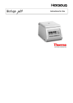
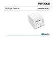
Instructions for use
#$ !
%# "
& ""
'$
()
%&
Biofuge
•
•
•
•
•
•
•
•
•
Safety regulations
Instrument description
Rotor program and accessories
Transportation and hook-up
Use of the centrifuge
Maintenance and care
Troubleshooting
Technical data
Index
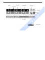
Overleaf you will find a graphic representation of the control panel of the
Biofuge fresco with a survey of the most
important functions
Please fold out
#$ !
%# "
& ""
'$
()
%&
Use this manual to get acquainted with your centrifuge
and its accessories.
The manual helps you to avoid inappropriate handling.
Make sure to keep it always close to the centrifuge.
A manual that is not kept handy cannot provide
protection against improper handling and thus
against damage to persons and objects.
This manual comprises chapters on
!
How to use this manual
temperature
rotor turns
quick run
open lid
stop
start
“set“ keys
mains switch
!
run time
#$ !
%# "
& ""
'$
()
%&
speed
Speed
Resting:
Run:
End:
Stop/run:
Time
Resting/end:
During run:
Temperature
Resting/end/
run:
preset speed
current speed; rotating light: rotor
turns
"End"
error codes
preset run time
remaining run time or (with quick start)
run time passed
current temperature of sample
Keys
Start:
Quick run:
normal start
short-term acceleration as long as key
is pressed, with indication of run time
passed
Stop:
"Set" keys:
open lid (possible only with mains
switch ON)
manual stop
stepwise increase/decrease of preset
values, accelerated change when
pressed permanently
Short pressing of any of the "set" keys: switch from
current to preset value
Error codes
(troubleshooting see chapter "Troubleshooting")
E-00:
E-4:
E-7:
E-8:
E-10:
E-11:
E-23:
br:
Lid:
OPEN:
motor blockage (transport protection removed?)
error in temperature measurement
actual temperature out of range
excess voltage
internal error (call Service)
internal error (call Service)
deviation in internal temperature calibration
power turned off during run or power failure
lid turned loose or opened during run
with lid closed: safety circuit triggered
Warnings can span several display panels
!
Display
Open lid:
#$ !
%# "
& ""
'$
()
%&
The control panel of the
Biofuge fresco
Contents
Proper use............................................................ 3
Improper use ........................................................ 3
Centrifuging hazardous materials ........................ 3
Handling ............................................................... 4
Conformity to current standards........................... 5
Safety instructions in this manual ........................ 5
The Biofuge fresco .................................. 7
Safety systems..................................................... 7
Features ............................................................... 8
Temperature regulation of the Biofuge fresco .... 9
"Quick run" operation ........................................... 9
Pieces delivered................................................. 10
Accessories ........................................... 11
Rotor program .................................................... 12
Adapters for rotor order no. 7500 3328 ............. 13
Before use.............................................. 15
Where to install the centrifuge ........................... 15
Mains connection ............................................... 15
Removing the transport protection..................... 15
Transport and installation................................... 17
Mains connection ............................................... 17
Opening the lid ................................................... 18
Emergency lid release.................................... 18
Inserting the rotor ............................................... 20
Permissible rotor temperature........................ 21
Lifetime of the rotor ........................................ 21
Removing the rotor............................................. 22
Loading the rotor ................................................ 22
Maximum loading ........................................... 22
Filling the centrifuge tubes ............................. 23
Aerosol-tight application..................................... 24
Checking for aerosol tightness........................... 25
Placing the tubes in the rotor ............................. 26
Selecting the speed............................................ 27
Selecting the run time ........................................ 27
Preselected run time ...................................... 27
Continuous operation ..................................... 28
Setting the temperature...................................... 28
Bringing the rotor to the desired temperature
in the centrifuge .............................................. 28
Starting the centrifuge ........................................ 29
Changing the settings during the run ................. 29
Stopping the centrifuge ...................................... 30
Stopping with preset time ............................... 30
Stopping with continuous operation ............... 30
!
For your safety......................................... 3
Operation ............................................... 17
#$ !
%# "
& ""
'$
()
%&
Contents
1
Contents
Maintenance and care ........................... 33
Maintenance to be performed by the customer . 33
Cleaning.......................................................... 33
Disinfection ..................................................... 34
Decontamination............................................. 36
Autoclaving ..................................................... 37
The Service of KENDRO.................................... 38
Warranty conditions ........................................... 38
Technical data........................................ 45
Component parts and performance ................... 45
The "Easycontrol" user interface........................ 47
Electrical connections/fuses............................... 49
Index ....................................................... 51
Autoclaving protocol............................. 57
Speed / RCF diagrams........................... 58
Troubleshooting .................................... 39
#$ !
%# "
& ""
'$
()
%&
Problems you can handle yourself..................... 39
In case you must call the Service....................... 43
2
!
Short-time centrifugation .................................... 30
RCF value .......................................................... 31
For your safety
For your safety
Proper use
Heraeus centrifuges are manufactured according to
current technical standards and regulations. Nonetheless, centrifuges may pose dangers if
The centrifuge is designed to separate liquidsuspended materials having different densities and
particle size, respectively. The maximum sample density is 1.2 g/cm3 at maximum speed.
• their design is improperly changed
• the safety instructions are not heeded
Therefore anybody concerned with operation and
maintenance of the centrifuge must read and follow the safety instructions.
In addition, the pertinent regulations for prevention of
accidents must be strictly followed.
This manual is an integral part of the centrifuge assembly and must be kept close at
hand at all times.
Improper use
During a run, a safety zone of 30 cm around the centrifuge must be maintained where neither persons nor
hazardous materials may be stationed.
The centrifuge may cause harm to you or other persons and may damage material goods if you do not
respect the following safety measures:
Centrifuging hazardous materials
• The centrifuge is neither made inert, nor is it explosion-proof. Therefore never use the centrifuge in an
explosion-prone environment.
• Explosive or flammable substances must not be
centrifuged. The same holds for substances prone
to react briskly with each other.
3
!
• they are operated by untrained personnel
#$ !
%# "
& ""
'$
()
%&
• they are not used as designed
For your safety
• Strongly corrosive substances that may cause damage to materials and impair the mechanical strength
of the rotor may be centrifuged only inside
protective vessels.
Handling
• Never use the centrifuge unless the rotor is properly
mounted.
• Never manually open the lid if the rotor still turns.
• Use only original parts for the centrifuge. The only
exception are common glass or plastic centrifuge
tubes if these are approved for the rotor speed and
RCF values of your rotor, respectively.
• Never use the centrifuge with the lid open.
• Never use the centrifuge if the paneling has been
partially or totally removed.
4
• You may use the centrifuge only with a properly
loaded rotor. You must not overload the rotor.
• If the rotor or the lid shows visible traces of corrosion or wear, you must stop using it.
• Strictly follow the rules and regulations for cleaning
and disinfection.
!
• Should toxins or pathogenic substances enter the
centrifuge or its parts, you must carry out the proper
procedures for disinfection (see "Maintenance and
care – Disinfection").
• Changes in mechanical or electrical components
may be carried out only by persons authorized to
this effect by KENDRO Laboratory Products.
#$ !
%# "
& ""
'$
()
%&
• Do not centrifuge toxic or radioactive substances or
pathogenic microorganisms unless you have taken
proper precautions.
Such precautions can e.g. consist of biological
seals.
For your safety
Conformity to current standards
Heraeus centrifuges are manufactured and tested
according to the following standards and regulations:
Safety instructions in this manual
This symbol denotes potential hazards to
persons.
This symbol denotes potential damage to the
centrifuge or parts in its immediate surroundings.
• IEC 1010-1 / EN 61010-1
!
for all voltages:
General hints are marked with this symbol.
• IEC 1010-2 / EN 61010-2-020
− Pollution degree 2
In addition, you are asked to adhere to the pertinent
regulations, in Germany
• CAN/CSA-C22.2 No. 1010.1-92
• Regulations for prevention of accidents BGV A2
• CAN/CSA-C22.2 No. 1010.2.020-94
• Regulations for prevention of accidents VBG 5
#$ !
%# "
& ""
'$
()
%&
− Overvoltage category II
for 110 V only:
• Regulations for prevention of accidents VBG 7z
• Regulations for prevention of accidents BGV D4
5
For your safety
#$ !
%# "
& ""
'$
()
%&
!
for your notes
6
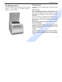
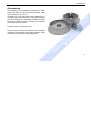
The Biofuge fresco
The Biofuge fresco is equipped with a number of safety
systems.
Rotor chamber
The rotor chamber consists of a stainless steel case
which is sealed against the motor with a rubber cover.
When the lid is closed, the rotor chamber is sealed
against the surroundings by a rubber ring with a special profile.
The rotor chamber is wrapped in evaporating tubing
filled with the ecologically harmless cooling agent
R134a, which is free from fluorinated/chlorinated hydrocarbons.
Warning if lid is manually opened during a run, or if
drive is overheated
If the lid is manually opened during a run, or if the temperature of the drive exceeds a critical value, a corresponding message appears in the display ("Lid" and
"OPEN", respectively).
Lid lock
You can open the lid only when the power is turned on
and the rotor has practically come to a halt (< 80 rpm).
You can start the centrifuge only if the lid is properly
closed.
7
!
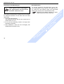
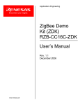
The figure below shows the Biofuge fresco with the lid
opened. In this state the standard display is
speed x 1,000 and "OPEN".
Safety systems
#$ !
%# "
& ""
'$
()
%&
The Biofuge fresco
Features
The Biofuge fresco is a refrigerated benchtop centrifuge for the preparation of sensitive samples in the
biochemical and medical laboratory.
The powerful refrigeration permits, at a room temperature of 25 °C, to maintain a sample temperature of 0 °C
over prolonged periods of time even at the maximum
speed of 13,000 rpm.
The preset speed is reached in seconds. You can also
spin samples for only a few seconds using the "quick
run" key ( ) if this is required for the task in question.
The extremely long-lived, maintenance-free induction
motor provides quiet and vibration-free operation even
at high speeds.
The user-friendly "Easycontrol" control panel permits
easy operation. With the centrifuge turned on and the
lid closed, the preset speed and run time and the actual temperature are displayed before the run. During
operation, the control panel shows the actual values;
or
upon briefly pressing any one of the "set" keys
8
the preset values for speed, run time and temperature
are indicated instead.
After the run, the speed control panel displays "End".
keys repeatedly, you increase
or
If you press the
the corresponding preset value stepwise. If you press
and hold down the chosen key, the respective value
increases continuously, at first slowly and, after a few
seconds, at an accelerated pace.
#$ !
%# "
& ""
'$
()
%&
Emergency lid release
In order to permit you to remove samples even after a
power failure, the centrifuge is equipped with an emergency lid release.
!
The Biofuge fresco
The Biofuge fresco
•
run time
•
temperature of the environment
•
location of the centrifuge
•
rotor speed
The Biofuge fresco is equipped with a powerful compression-type refrigeration. Possible settings are from
-9 °C to +40 °C. For short-term operation requiring
precise temperature control, both the rotor and the
rotor chamber must be preadjusted to the desired temperature.
) is pressed, the
As long as the "quick run" key (
rotor is accelerated with maximum power, potentially
up to the maximum speed.
!
During a run, the spinning rotor creates frictional heat.
This leads to a temperature increase of the rotor, the
tubes and finally of the samples. The extent of warming
depends on:
"Quick run" operation
#$ !
%# "
& ""
'$
()
%&
Temperature regulation of the
Biofuge fresco
9
The Biofuge fresco
Pieces delivered
The Biofuge fresco is delivered complete with:
• a special cap nut for fixing the rotor
• 10-mm tubular socket wrench for fastening the
cap nut
• cable for mains connection
tubular socket
wrench
order no.
2036 0072
#$ !
%# "
& ""
'$
()
%&
• this Manual
cap nut
order no.
70056208
10
!
• fixed-angle rotor 24 x 1,5 / 2 ml 7500 3328
Accessories
Accessories
!
The Biofuge fresco is delivered complete with a fixedangle rotor with 24 holes for placing microliter tubes
with a volume of 1.5 or 2.0 ml.
In addition you may order three sets of adapters containing 24 reduction sleeves each. With these adapters
you can centrifuge all commercially available microliter
tubes with a volume between 0.2 and 0.6 ml as well as
0.2-ml PCR reaction vessels.
Please consult our sales documentation for a complete
collection of accessories including technical data, order
numbers and special low-cost package offers.
#$ !
%# "
& ""
'$
()
%&
A further option is a PCR-Strip rotor.
11
Accessories
Rotor designation
order no.
places / volume
PCR-rotor
7500 3328
7500 3327
24 x 1,5 / 2 ml
4 x PCR-Strip
24 x 4
4x4
-1
13 000
13 000
-1
minimum speed nmin [ min ]
2 000
2 000
maximum RCF value at nmax
16 060
12 846
( 11 524* )
maximum radius [ cm ]
8,5
6,8
( 6,1* )
minimum radius [ cm ]
5,9
6,1
( 4,7* )
angle
40
45
acceleration / deceleration time [ s ]
15 / 16
15 / 16
min. temperature at nmax [ °C ]
0
0
aerosol-tight
yes (reduced filling)
yes (reduced filling)
permissible temperature range
autoclavable (number of cycles)
-4 °C to +40 °C
121°C, (10 cycles)
-4 °C to +40 °C
121°C, (10 cycles)
maximum speed nmax [ min ]
[°]
relative to room temperature 25°C
* The values relate to vessel places 4 and 5 in the PCR-Rotor
12
( 32 x 0,5 )
#$ !
%# "
& ""
'$
()
%&
maximum permissible load [ g ]
Microliter rotor
24 x 2 ml PP
!
Rotor program
Accessories
Dimensions
(∅ x H)
Capacity
Number per
Set
Color
Order No.
reduction sleeve PCR
6,2 x 20 mm
0,2 ml
24
gray
7600 3750
reduction sleeve
8 x 43,5 mm
0,5/0,6 ml
24
turquoise
7600 3758
reduction sleeve
6 x 46 mm
0,25/0,4 ml
24
red
7600 3759
#$ !
%# "
& ""
'$
()
%&
Adapter
!
Adapters for rotor order no. 7500 3328
13
#$ !
%# "
& ""
'$
()
%&
!
for your notes
14
Before use
The centrifuge may only be used indoors. Its location
must meet the following criteria:
• A safety zone of 30 cm around the centrifuge must
be maintained. Hazardous materials must not be
kept within this zone during centrifugation.
• The substructure must be stable and resonancefree. A good support is provided by a plane laboratory bench or a large laboratory carriage with casters that may be locked.
• To ensure sufficient air circulation, a minimum distance from the wall of 10 cm at the back and of
15 cm on each side must be kept.
• The centrifuge must be protected from heat and
direct sunshine.
• The location should be well ventilated.
Make sure that the mains supply you use for the centrifuge meets the specifications printed on the type plate.
Turn the mains switch off (press "0"); only then connect
the centrifuge with the mains supply using the power
cord supplied with the instrument.
Removing the transport protection
Turn the instrument on. The display panel shows for
about 6 s the routine internal software check sequence. Open the lid by pressing the "open lid" key
and remove the transport protection for the rotor.
Check that the rotor moves freely by lightly turning it,
and make sure the rotor is tightly screwed on.
15
!
Where to install the centrifuge
Mains connection
#$ !
%# "
& ""
'$
()
%&
Before use
Before use
#$ !
%# "
& ""
'$
()
%&
!
for your notes
16
Operation
Transport the centrifuge only in the
upright position using the special
box provided with the instrument
and secure it properly. Place the
centrifuge carefully.
Before using the centrifuge, make sure that
the transport protection has been removed!
In order to allow the coolant to settle
down in the compressor, the
instrument must be left idle at the
new location for about ½ to 1 hr.
The Biofuge fresco is now ready for use.
Make sure that your mains voltage and frequency
match the specifications on the instrument. Turn off the
mains switch on the lower right of the instrument (push
down the "0" marking), then connect the instrument to
the mains supply.
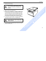
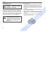
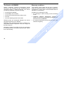
Turn on the mains switch
on the lower right (see figure)
mains switch
For a couple of seconds the following reading appears
in the control panel:
This tells you that the
instrument carries out
an internal check of its
software.
After a couple of seconds the display changes. The
values now shown are (except for the temperature) the
ones last used. The temperature reading gives the
current temperature of the sample (before the start
normally the temperature of the rotor chamber).
17
!
Transport and installation
Mains connection
#$ !
%# "
& ""
'$
()
%&
Operation
Operation
Opening the lid
Rotor can spin at high speed!
Touching it may cause severe
injuries!
Always wait for several minutes until
the rotor has come to a complete
stop. Without power the brake does
not function, and braking takes
much longer than normal!
#$ !
%# "
& ""
'$
()
%&
For normal electrical unlocking, connect the centrifuge
to the mains supply, turn the mains switch on and push
the "open lid" key .
Emergency lid release
In case of a power failure you cannot open the lid normally using the "open lid" key (see previous section).
To permit unloading even in this case, the centrifuge is
equipped with a mechanical lid unlocking system. However, you may use this system only in case of emergency.
Should it be necessary to open the lid manually, carry
out the following steps:
18
!
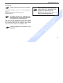
The following figure gives an example of possible readings. A detailed description of possible settings is given
below.
In this example, the
preset speed is 5,000
rpm, the preset run
time is 10 min, and the
current
temperature
reading is 21 °C.
Operation
1. Unplug the mains plug.
Never brake the rotor using your
hands or tools!
#$ !
%# "
& ""
'$
()
%&
2. Make sure the rotor stands still.
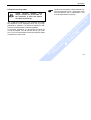
3. Push a thin screwdriver or another suitable tool
horizontally from each side through the two openings in the side panels of the centrifuge (see figure).
Push the locking pins under the side panels simultaneously from both sides until the lid unlocks audibly. Remove the auxiliary tools and open the lid.
4. In case the rotor still turns, close lid immediately
and wait until it has come to a complete stop.
!
Pull the mains switch before actuating the mechanical emergency lid
release!
5. As soon as the rotor stands still, remove your samples and close the lid.
19
Improper or improperly combined
accessories may cause severe
damage to the centrifuge!
Rotors which are allowed for use in a Biofuge fresco
centrifuge are detailed in the chapter "Accessories",
and only these rotors are to be used in this centrifuge.
To insert the rotor you will need the cap nut and the
socket wrench delivered with the centrifuge (see the
chapter “The Biofuge fresco – Pieces delivered”).
Possible damage to drive and rotor!
You may insert the rotor only if the
temperature of the drive, the rotor
and the cap nut is between 10 °C
and 30 °C.
20
Proceed as follows:
1. Open the lid and make sure that the rotor chamber
and the rotor are clean. Remove eventual dust, foreign material or sample residues. The thread and
the O-Ring on the motor shaft must be in perfect
condition.
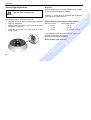
2. Turn the rotor so that the notch for engaging the
drive shaft points downward.
3. Place the rotor on top of the drive shaft so that the
notch of the rotor is located precisely above the retaining pin.
4. Push the rotor gently down until the thread is completely laid bare (see figure).
#$ !
%# "
& ""
'$
()
%&
Inserting the rotor
!
Operation
Operation
Regularly check the proper positioning of
the rotor and retighten the cap nut as
needed.
The rotors are only to be used
within the temperature range from 4oC to +40oC. Pre-cooling in the
freezer is not permitted
Lifetime of the rotor
There is no limitation on the service life of the high
performance rotors. However please observe the following due to safety reasons:
Rotors and accessories made of
plastic should not be exposed to
direct sunlight and UV rays!
If the rotor shows signs of discoloration, deformation or wear, or is out
of balance it must be exchanged
straight away!
21
!
Do not push the rotor down using
force. If you cannot screw on the
cap nut, you must carefully lift off
the rotor and insert it again.
Permissible rotor temperature
#$ !
%# "
& ""
'$
()
%&
5. If you have placed the rotor correctly, you can
screw on the cap nut easily and secure it with the
tubular socket wrench delivered with the instrument.
6. Place the rotor cap onto the rotor.
Operation
Removing the rotor
Loading the rotor
To remove the rotor, you must follow the steps described above in reverse order.
With the hermetic lid, you may in case of contamination
separate the rotor from the drive without opening the
lid! In this case you can open rotor upon removal from
the centrifuge using e.g. a safety work bench before
decontaminating it.
Maximum loading
Never tilt the rotor. Always grab it in
the middle and pull out perpendicularly.
1. Open the lid of the centrifuge.
2. Screw the cap nut open by turning it counterclockwise using the socket wrench delivered with the instrument. Remove the cap nut.
3. Grab the rotor in the middle and pull gently upwards
off the drive shaft. Be careful not to jam it.
!
The Biofuge fresco can reach high rotational speeds
implying enormous centrifugal force. The rotors are
designed in a way warranting sufficient residual
strength even at the highest permissible speed.
However, this safety system presupposes that the
maximum permissible load of the rotor is not exceeded.
If you wish to centrifuge samples that together with the
adapters exceed the maximum permissible load, you
must either reduce the sample volume or calculate the
permissible speed nperm according to the following formula:
#$ !
%# "
& ""
'$
()
%&
Danger of irreparable motor damage!
Overloading may cause the rotor to
explode! Exploding parts may
severely damage the centrifuge!
n
22
perm
=n
max
∗
maximum permissible load
actual load
Operation
The smaller the unbalance of the centrifuge, the better
the separation since separated zones are no longer
perturbed by vibration. It is therefore important to balance the centrifuge tubes as well as possible.
To minimize unbalance you should fill the tubes as
evenly as possible. You can achieve this by eye. However, you must nonetheless ensure that opposite tubes
are filled to the same level.
!
Check carefully whether your
sample vessels are permissible for
the respective g value and reduce
the speed if necessary.
Please note that plastic sample vessels only
have a limited service life - particularly when
used at maximum rpm or temperature - and
must be replaced as necessary!
#$ !
%# "
& ""
'$
()
%&
Filling the centrifuge tubes
23
Operation
Aerosol-tight application
not with open container lids!
Attention :
Please check that your sample containers are suitable
for the centrifugal application desired.
(16060 x g ; temperature in uncooled devices approx.
10 K above room temperature)
Lubricate the seals before inserting them (lubricant
order no. 75003500)
•
Insert the seal (C profile) in the groove at the side
of the body of the rotor.
•
Insert the O-ring into the inner groove on the
screw-on top.
Please observe the permissible filling volumes!
Nominal volume:
Permissible volume:
2.0 ml
1.5 ml
1.5 ml
1.0 ml
2
others
/3 nominal volume
#$ !
%# "
& ""
'$
()
%&
•
The sealing elements are to be checked regularly for
damage to the shape and surface!
Exchange faulty parts immediately.
Spare sealing rings 75003268
24
!
The following steps have to be carried out:
Operation
To carry out the test, proceed as follows:
•
Carefully clean and degrease the rotor chamber
wall, then attach an adhesive white paper strip
(about 4 x 2 cm) so that liquid leaking out of the rotor may precipitate on it.
•
Fill all places of the respective rotor with water
according to the following Table. Insert the rotor
into the centrifuge and fasten it.
•
Carefully place the amount of test liquid (0.5 %
sodium fluorescein in water) specified in the column “leakage test” into the lower part of the rotor
within a virtual circle comprising the vessel bores
(not the bores themselves) using a pipette or syringe.
•
Place the rotor lid on top and screw it on.
ATTENTION: Make sure that there is no spilled
test liquid on the rotor (clean if necessary)!
•
Carry out a test run for 10 minutes at maximum
rotor speed and 23 °C ambient temperature.
Check the paper strip under UV light (preferentially
in a darkened room):
If there is no detectable fluorescence, the test is
considered passed.
•
Finally rinse rotor, rotor lid and lid seal in running
water and allow to dry.
!
Check the aerosol tightness of your
rotor whenever appropriate.
•
#$ !
%# "
& ""
'$
()
%&
Checking for aerosol tightness
25
Operation
Placing the tubes in the rotor
Improper loading can in the worst
case lead to damage to rotor and
centrifuge. Unbalance not only
causes a noisy run, but rapidly
damages the motor suspension.
!
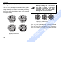
The rotor must be loaded symmetrically. When loading
the rotor only partially, you must ensure that opposite
bores always receive tubes of equal weight (when centrifuging a single sample, place a centrifuge tube e.g.
filled with water). The following figure gives examples
for proper loading.
#$ !
%# "
& ""
'$
()
%&
improperly loaded rotors
When you have loaded the tubes, fasten the rotor lid
by screwing the cap nut centrally on it.
Close the lid of the centrifuge by firmly pressing it
down. There must be a clicking sound, and the lid must
be locked so that it cannot be opened manually.
properly loaded rotors
26
Selecting the speed
Selecting the run time
The minimum speed of the rotor is 2,000 rpm, the
maximum speed 13,000 rpm. The built-in microprocessor prevents higher or lower speed settings. Between
these extremes, you can select the speed in steps of
100 rpm using the following procedure:
(increase) or
1. Press one of the "set" keys
(decrease) in the speed control section of the
control panel (cf. foldout leaf in the cover):
By pressing the key briefly,
you increase or decrease the
speed in steps of 100 rpm.
This option is supposed to be
used for small changes and
fine tuning.
2. If you keep the key pressed, the display changes
at first slowly and after a few seconds at an accelerated pace.
3. Release the key as soon as you are close to the
desired value, and fine tune if necessary by repeatedly pressing the selected key (or its counterpart if you have proceeded too far in one direction). The first digit after the decimal point flashes
for a few seconds and then turns permanent. The
speed is now stored.
You can select a run time between 1 and 99 min or
continuous operation.
#$ !
%# "
& ""
'$
()
%&
Preselected run time
To predetermine the run time, proceed as follows:
(de(increase) or
1. Press one of the "set" keys
crease) in the run time section of the control panel
(cf. foldout leaf in the cover):
By pressing the key briefly, you
increase or decrease the preset
run time in steps of 0.1 min.
This option is supposed to be
used for small changes and fine
tuning.
2. If you keep the key pressed, the display changes at
first slowly and after a few seconds at an accelerated pace.
3. Release the key as soon as you are close to the
desired value, and fine tune if necessary by repeatedly pressing the key (or its counterpart if you have
proceeded too far). The display flashes for a few
seconds and then turns permanent. The run time is
now stored.
27
!
Operation
Please note that the lifetime of plastic tubes
in particular is limited. Extended use may
damage them.
Setting the temperature
The temperature is set as follows:
(increase) or
1. Press one of the "set" keys
(decrease) in the run temperature section of the
control panel (cf. foldout leaf in the cover):
By pressing the key briefly, you
increase or decrease the temperature in steps of 1 °C. This option is
supposed to be used for small
changes and fine tuning.
2. If you keep the key pressed, the display changes at
first slowly and after a few seconds at an accelerated pace.
28
3. Release the key as soon as you are close to the
desired value, and fine tune if necessary by repeatedly pressing the key (or its counterpart if you have
proceeded too far). The display flashes for a few
seconds and then turns permanent. The temperature setting is now stored.
The refrigeration starts operating at once if the preselected temperature is below the temperature of the
rotor chamber.
Bringing the rotor to the desired temperature in the
centrifuge
You can precool or preheat the rotor inside the centrifuge by using the following procedure:
1. Insert the rotor if not already in place.
Attention! To avoid jamming, do not tilt the rotor!
Read the pertinent hints in the chapter "Before
use".
2. Adjust the temperature as desired using the keys
in the temperature control panel as described
above.
3. Set the speed to the maximum value.
4. Select a run time of 15 min and start the centrifuge by briefly pressing the start key .
#$ !
%# "
& ""
'$
()
%&
Continuous operation
repeatedly
For continuous operation, press the key
or press and hold until "hd" (for "hold") appears in the
display.
With this setting, the centrifuge keeps running until
stopped manually.
!
Operation
Operation
Starting the centrifuge
in the control panel. The centriPress the "start" key
fuge accelerates to the preselected value. Simultaneously, the run time display starts going backwards from
the preset time, giving the remaining run time in minutes. After reaching the last minute the display
switches to seconds remaining. The rotating light tells
you that the centrifuge is running. During the run, you
cannot open the lid.
Changing the settings during the run
You can change the settings while the rotor is spinning
(not in the "quick run" mode, see section "Short-time
centrifugation" below). The altered value flashes for a
few seconds, then changes to continuous display. At
the same time the new values are activated.
29
!
Once the rotor is in place, the main switch turned on
and the lid closed, you can start the centrifuge.
#$ !
%# "
& ""
'$
()
%&
If you wish to change the temperature of your samples,
please consider that the time required for temperature
adjustment is prolonged. The farther apart initial and
final temperature, the longer it takes for the temperature to adjust.
The temperature reading does not give the
change in the temperature of the sample
(the reading is delayed with respect to the
actual temperature change). You cannot
follow the heating or the cooling of the samples directly. For critical applications you
should take other precautions to ensure that
the desired temperature is actually reached
and maintained (e.g. by measuring the temperature immediately after the run).
Stopping the centrifuge
Short-time centrifugation
Stopping with preset time
Normally the run time has been preselected, and all
you have to do is wait until the centrifuge terminates
the run automatically. As soon as the speed is close to
zero, the display reads "End". By pressing the "open
you can now open the lid and remove the
lid" key
samples.
You can also terminate the run at any time as described under "Stopping with continuous operation".
For short-term operation, the Biofuge fresco is
equipped with the "quick run" function.
Short-term centrifugation is started by pressing the
"quick run" key
continuously; it stops as soon as the
key is released.
In this mode the centrifuge accelerates with full power
up to the maximum speed of 13,000 rpm unless you
release the "quick run" key
The preset speed is ignored.
30
The centrifuge accelerates to the
maximum speed of 13000 min-1.
#$ !
%# "
& ""
'$
()
%&
Stopping with continuous operation
If you have chosen continuous operation, you must
stop the centrifuge manually by pressing the "stop" key
in the control panel. The centrifuge starts braking at
once and stops within a few seconds. The speed display changes to "End", and the electrical unlocking
mechanism of the lid is available. You can now open
.
the lid by pressing the "open lid" key
Check carefully whether you have to
maintain a specific speed for your
application.
During acceleration the time is counted forward in seconds. After 60 seconds the display changes to the
minute mode.
!
Operation
Operation
2
n
RCF = 1118
. ∗
∗r
1000
r = radius of centrifugation in cm
n = speed in rpm
At a speed of 13000 min-1, the
centrifuge achieves a maximum
performance of 16060 g!
Check carefully whether your tubes
are designed for this centrifugal
force, and reduce the speed if
necessary.
Please note that this value becomes lower
depending on the tubes and adapters used.
You may take this into account when calculating the
RCF value for your application.
The figure on the last page of this manual gives a
graphic representation of the relation between speed
and RCF.
Apart from the maximum RCF value RCFmax (lower
line) this graph also shows the minimum RCF value
RCFmin, calculated for the meniscus of the sample (upper line).
31
!
The relative centrifugal force (RCF) is usually given in
multiples of the earth gravity g. It is a dimensionless
number that allows one to compare the efficiency of
separation or sedimentation of diverse instruments,
since it is independent of the instrument used. The only
values entered in the equation are radius and speed of
centrifugation:
The figure for the maximum RCF value is based on the
maximum radius of the tube.
#$ !
%# "
& ""
'$
()
%&
RCF value
Operation
#$ !
%# "
& ""
'$
()
%&
!
for your notes
32
Maintenance and care
For the protection of persons, environment and material you are obliged to clean the centrifuge regularly
and to disinfect it if necessary.
Unsuitable cleaning agents or disinfection procedures may damage the
centrifuge and its accessories!
If you intend to use cleaning agents
or disinfection procedures not recommended by the manufacturer,
you have to make sure by consulting the manufacturer,
that the
procedure foreseen does not cause
any damages to the instrument!
Pull mains plug before cleaning the instrument!
Clean the casing, the rotor chamber, the rotor and the
accessories regularly and in case of need. This is indicated both for reasons of hygiene and to prevent corrosion due to contamination sticking to the instrument
and its accessories.
Clean them with mild agents of pH values ranging from
6 to 8.
For other cleaning agents please consult KENDRO!
Immediately after cleaning, dry the aluminum parts or
put them into a warm-air dryer at a temperature not
exceeding 50°C.
33
!
Maintenance to be performed by the
customer
Cleaning
#$ !
%# "
& ""
'$
()
%&
Maintenance and care
Maintenance and care
Instruments with refrigeration unit:
If a strong ice sheet is present in the internal
chamber, be sure to remove all condensate
after defrosting!
Please control and clean the venting slots
regularly!
Before cleaning the venting slots
please disconnect the centrifuge from
the mains supply.
Please pull mains plug!
34
Infectious material could enter the centrifuge if spills or tube breakage occur.
Danger of infection may occur upon
contact! Take appropriate protective
measures for personnel!
Mind the permissible filling volumes and
loading limits for the tubes!
In case of contamination the operator has
to make sure, that no further persons are
jeopardized!
Contaminated parts have to be decontaminated immediately.
If required further protective measures
have to be initiated.
!
Organic solvents may decompose
the lubricant of the motor bearing.
The drive shaft may block.
#$ !
%# "
& ""
'$
()
%&
During cleaning liquids and especially organic solvents should not
come into contact with the drive
shaft and the ball bearing.
Disinfection
If a centrifuge tube containing infectious material leaks
during a run, you have to disinfect the centrifuge immediately.
• Please use 70% ethanol for disinfection.
Please note the safety measures
and handling hints when applying
these substances!
For other disinfectants please consult KENDRO
Services!
• You may disinfect the rotor and the accessories as
described in the following section. Be sure to follow
the pertinent safety procedures for handling infectious material.
1. Pull mains plug.
2. Unscrew the rotor chuck.
3. Grab the rotor with both hands and pull it
perpendicularly off the drive shaft.
4. Remove the centrifuge tubes and adapters, and
disinfect them or dispose of them as necessary.
5. Treat the rotor and the rotor lid according to the
instructions given for the disinfectant (soaking in liquid or spraying). You must strictly observe the
specified action times!
6. Turn the rotor head down and drain off the disinfectant. Thereafter thoroughly rinse rotor and lid with
water.
7. Dispose of the disinfectant according to valid regulations.
8. Aluminum rotors have to be treated with anticorrosive protective oil subsequently.
#$ !
%# "
& ""
'$
()
%&
Rotor and rotor chamber must be treated with a neutral, universal disinfectant. Best suited for this purpose
are disinfectant sprays, ensuring that all rotor and
accessory surfaces are covered evenly.
35
!
Maintenance and care
Maintenance and care
The following precautionary measures are to be taken
for extensive protection of the 7500 3327 and 7500
3328 rotors:
1. Avoid high temperatures!
The bleaching solution and the rotor should not be
warmer than ca. 25 °C.
2. Do not let the bleaching solution act longer than
absolutely necessary!
3. After disinfection, rinse the rotor thoroughly with
distilled water and allow to dry.
36
For general radioactive decontamination, use a solution of equal parts of 70% ethanol, 10% SDS and water. Follow this with ethanol rinses, then de-ionized
water rinses, and dry with a soft absorbent cloth.
Dispose of all washing solutions in appropriate radioactive waste containers!
!
These agents contain highly aggressive hypochlorites and must not be
used with aluminum rotors!
Decontamination
#$ !
%# "
& ""
'$
()
%&
Disinfection with bleaching lye
Maintenance and care
Autoclaving
You may autoclave the rotor and the adapters at
121 °C.
Maximum permissible autoclaving cycle:
20 min at 121 °C.
Never exceed the maximum permissible values for autoclaving temperature and autoclaving time.
Should the rotor show signs of
wear, you must stop using it!
!
Check whether autoclaving is permitted!
The rotor must be cleaned and rinsed with distilled
water before being autoclaved. Remove the rotor lid,
the centrifuge tubes and the adapters. Place plastic
rotors on an even surface to avoid deformation.
Chemical additives to the steam are not
permitted.
#$ !
%# "
& ""
'$
()
%&
For safety reasons, the 7500 3327 and
7500 3328 rotors must only be subjected
to a maximum of 10 autoclavings!
37
Warranty conditions
Kendro Laboratory Products recommends annual
servicing of the centrifuge and the accessories by the
authorized service or skilled personnel. The service
provided by KENDRO comprises checking:
The warranty period starts with the day of delivery.
Within the warranty period the centrifuge is repaired or
replaced free of cost if there are demonstrable faults in
materials or workmanship.
Conditions for a warranty are that:
• the suitability of the location
• the lid lock mechanism and the safety circuit
• the rotor
• the rotor fastening and the drive shaft
Defective parts are exchanged. Besides, the service
personnel cleans the rotor chamber.
KENDRO offers inspection and service contracts covering these benefits. Inspection costs are charged as
flat-rate contracts.
Necessary repairs are carried out free of cost during
the warranty period, and against payment after expiration of the warranty.
38
• the centrifuge is used according to the instructions
of use
• installation, additions, adjustments, changes or
repairs are carried out exclusively by personnel authorized for this by KENDRO
• the required maintenance and care procedures are
carried out regularly.
#$ !
%# "
& ""
'$
()
%&
• the electrical installation
!
The Service of KENDRO
Troubleshooting
Troubleshooting
Problems you can handle yourself
Behavior of the centrifuge
Possible cause(s) and measures to be taken
Displays remain
dark
The motor stops.
The rotor stops without braking.
The lid cannot be opened.
Mains failure or not connected
1. Is the mains switch turned on?
2. Check the mains connection.
3. If the mains connection is OK, call the nearest Service.
Displays fail briefly
The motor stops suddenly.
The rotor stops without braking.
The display reads "br", see br.
Brief interruption of mains supply
1. Check whether the plug is plugged in properly.
2. Wait for 75 seconds.
3. Restart the centrifuge.
Loud running noise
Centrifuge is exceptionally noisy.
, in case of
1. Stop the centrifuge by pressing the key
emergency pull mains plug.
2. Wait until the centrifuge stands still.
3. Check whether the rotor is properly loaded.
4. Check whether a broken vessel, damage to the rotor or
motor malfunction was responsible for the noise.
5. If you cannot locate and solve the problem, call Service.
#$ !
%# "
& ""
'$
()
%&
Error
!
If problems other than those described in the following tables arise, you must consult your nearest
authorized service.
39
Error
Behavior of the centrifuge
Possible cause(s) and measures to be taken
Lid cannot be
opened
Pressing the "open lid" key has
no effect.
A) Lid not correctly engaged or lid warped.
1. Check whether the mains supply is OK and the instrument is switched on (displays lit).
2. Press the lid down in the middle of the front section and
actuate the "open lid" key once again.
3. In case these measures have not the desired effect, you
may open the lid with the emergency lid release. (see
page 18).
B) Heat monitoring relays in the lid unlocking magnets
have been actuated.
#$ !
%# "
& ""
'$
()
%&
Press the key again after waiting for about 1 min.
br
Instrument was switched off during run, or brief mains failure.
If the instrument was switched off inadvertently, switch on
again. Wait for about 75 seconds. The centrifuge comes to a
stop without braking.
E-00
Motor does not start.
Motor or rotor is blocked.
1. Switch the instrument off and on again using the mains
switch.
2. Open the lid.
3. Remove transport protection from the rotor.
40
!
Troubleshooting
Troubleshooting
Behavior of the centrifuge
Possible cause(s) and measures to be taken
E-4
Error in temperature measurement
1. Switch the instrument off and on again.
2. If the error persists, call Service.
E-7
Actual temperature outside tolerance (<-10 °C or >50 °C)
Switch the instrument off and on again. Should the display
"E-7" persist, the temperature control circuit is defective.
Please call your nearest Service.
E-8
Overvoltage or over-current at
the U/F converter
Mains voltage outside tolerance. Brake resistance defective.
Switch the instrument off and on again. If the problem
persists, call Service.
E-10
Wrong check sum in the NVRAM
Switch the instrument off and on again. If the problem
persists, call Service.
E-11
Error in data transfer from NVRAM
Switch the instrument off and on again. If the problem
persists, call Service.
E-23
Deviation in the internal temperature adjustment
Switch the instrument off and on again. If the problem
persists, call Service.
#$ !
%# "
& ""
'$
()
%&
!
Error
41
Error
Behavior of the centrifuge
Possible cause(s) and measures to be taken
"Lid" appears in the
display
Motor stops.
Rotor comes to a stop without
braking.
The lid was manually opened during the run.
1. Press the lid shut. The instrument comes to a stop without braking.
2. If you want to continue the centrifugation, you must
switch the instrument off and on again. The message "br"
is displayed and the centrifuge brakes (see br).
The safety circuit has been actuated.
1. Pull the mains plug.
2. Control ventilation slots and clean if necessary.
3. After 20 min you can start the instrument again.
4. If the safety circuit is again actuated, call Service.
42
Start impossible
The safety circuit has been actuated.
1. Pull the mains plug.
2. Control ventilation slots and clean if necessary.
3. After 20 min you can start the instrument again.
4. If the safety circuit is again actuated, call Service.
#$ !
%# "
& ""
'$
()
%&
Display "OPEN"
appears although
lid is closed
!
Troubleshooting
Troubleshooting
In case you must call the Service
!
Should you require our Service, please tell us the order
no. and serial number of the instrument. You find the
pertinent information at the back of the instrument near
the socket for the mains plug.
Moreover it is helpful for our service technician (and
saves you expenses) to know the valid software version. You can determine the software version as follows:
1. Switch the instrument off.
2. Switch the instrument on.
Subsequently, the display may read e.g. 0978 06
(processor 0978 version 06) for about 2 seconds.
For approximately another 2 seconds, the display
may read e.g. 415 8 03 (NV-RAM 4158 version 03).
#$ !
%# "
& ""
'$
()
%&
The display reads 888 88 88 for a couple of seconds.
43
Troubleshooting
#$ !
%# "
& ""
'$
()
%&
!
for your notes
44
Technical data
Technical data
Description
Design
Armored case: stainless steel
Frame: torsion resistant, hot galvanized steel plates
Body and front panel: impact-resistant, highly dampening plastic
Lid: stove-enameled steel plate with integral high-resistance foam
insulation
Keys and display panel
Keys and display panel covered with easy care protective foil
Control elements
User-friendly "Easycontrol" system
Rotor chamber
Material: stainless steel
Dimensions (diameter x height): 180 mm x 54 mm
Lid release
Electromagnetic release with key
Lid lock
Automatic locking when the lid is pressed down
Emergency lid release
Lid release in case of mains failure: emergency release with straight pins
#$ !
%# "
& ""
'$
()
%&
Part / function
!
Component parts and performance
when switched on.
45
Technical data
environmental conditions
Value
-
indoor use
-
max. elevation 2000 m above sea level
-
max. relative humidity 80 % up to 31 °C; linearly decreasing down to
50 % relative humidity at 40 °C.
10 °C to 35 °C during operation (no condensation)
-10 °C to 50 °C for storage and shipping
maximum speed nmax
13,000 min-1
minimum speed nmin
2,000 min-1
maximum RCF value at nmax
16,060
maximum kinetic energy
1.65 kNm
set temperature range
-9 °C to +40 °C
noise at maximum speed
< 55 dB (A); <45 dB (A) with standstill refrigeration
dimensions (H x W x D)
305 mm x 290 mm x 450 mm
weight without rotor
27 kg
46
#$ !
%# "
& ""
'$
()
%&
permissible temperature of the environment
!
Function / parameter
Technical data
The "Easycontrol" user interface
Function
Performance
Start
Start key (
)
Stop
Stop key (
)
Quick starting and stopping
"Quick run" key (
when released
Indication of operating state
Spinning rotor indicated by rotating lights (LED) in the speed display
panel
End of centrifugation
Speed display reads "End"
Digital parameter display
•
•
•
Speed selection
adjustable in steps of 100 min-1 in the range 2000 min-1 to 13,000 min-1
Run time selection
adjustable in minutes between 1 min and 99 min;
"hd" mode: continuous operation
Temperature selection
adjustable in steps of 1 K between -9 °C and 40 °C
#$ !
%# "
& ""
'$
()
%&
speed
run time
temperature
!
): short-time run when pressed permanently; stop
47
Technical data
Performance
Time display in "quick run" mode
between 1 s and 60 s in seconds, above 60 s in minutes
Parameter memory
•
•
•
for speed
for run time
for temperature
Diagnostics
•
•
lid not properly closed: display "OPEN"
general faults in performance (error codes)
120 / 100V instruments
Manufactured and tested in accordance
with
48
EN 61 010-1, EN 61 010-2-020
EN 61326 (+ EN 61000-3-2/A14:2000-6)
EN 55011 B
#$ !
%# "
& ""
'$
()
%&
Testing standards
230V instruments
Manufactured and tested in accordance
with
!
Function
IEC 61010-1:1990 + amendment 1:1992 + amendment 2:1995
IEC 61010-2-020:1993 + amendment 1:1996
CAN/CSA-C22.2 No. 1010-1.92
CAN/CSA-C22.2 No. 1010-1.B97 amendment 2
Technical data
Order no.
Voltage
Frequency
max. current
Power consumption
Fuses inside instrument *
7500 5521
230 V
50/60 Hz
1.7 A
270 W
2 x 4 A slow-blow
(5 x 20 mm)
7500 5522
120 V
60 Hz
3.8 A
270 W
1 x 6.25 A slow-blow
(6.3 x 32 mm)
!
Electrical connections/fuses
#$ !
%# "
& ""
'$
()
%&
* The fuse may be replaced only by authorized servicing personnel!
49
Technical data
#$ !
%# "
& ""
'$
()
%&
!
for your notes
50
Index
Index
C
cap nut
for fixing rotor 10
centrifuge
starting 29
centrifuge tubes
contamination
necessary measures 34
!
acceleration 8
accessories
cap nut 10
rotor 11
tubular socket wrench 10
aerosol tightness
check 25
aluminum rotor: 35
autoclaving 37
autoclaving cycle
permissible maximum 37
continuous operation 28, 30
control panel
readings 8
coolant
environmentally safe 7
corrosive substances
protective vessels for 4
D
damage
symbol for potential 5
dangerous chemicals 3
decontamination 34
disinfectant 35
disinfection 4
procedure 35
#$ !
%# "
& ""
'$
()
%&
A
types 11
volume range 11
cleaning 33
conditions of warranty 38
51
Index
EC Guidelines 5
electrical connections 49
emergency lid release 18
error code
"br" 40
"Lid" 42
"OPEN" 42
E-00 40
E-10 41
E-11 41
E-23 41
E-4 41
E-7 41
E-8 41
fine tuning
run time 27
speed setting 27
temperature 28
fixed-angle rotor 11
fluorescein
test solution for aerosol tightness 25
formula
maximum permissible load 22
fuses 49
H
hazardous substances 3
hazards
symbols used for 5
hints
symbol for 5
I
icons
for denoting dangers and potential damage 5
52
!
E
F
#$ !
%# "
& ""
'$
()
%&
disinfection with bleaching lye 36
display
during run 29
displays
brief failure 39
not lighted 39
Index
K
key
"open lid" 30
"quick run" 8
"set" 8
"start" 29
keys
general operation 8
L
lid
!
lid open during run
warning 7
lid opening 18
lid release
emergency 8, 18
manual 18
light
rotating 29
location 15
M
mains connection 15
mains switch 17
maintenance 33
manual lid release 18
steps for 18
maximum permissible load
formula for 22
maximum sample density 3
min. temperature 12
minimum sample temperature 8
#$ !
%# "
& ""
'$
()
%&
indoor use 15
infectious material
precautions in case of tube breakage 34
installation
place of 15
Instructions for use
delivered with instrument 10
items delivered 10
blockage 40
lid lock
built-in safety system 7
53
Index
P
partial loading
of rotor 26
pathogenic microorganisms
protection against 4
permissible speed 22
power on 17
power supply 15
precooling
of rotor inside centrifuge 28
54
Q
quick run function 30
quick run key 8
!
open lid key 30
opening the lid 18
operation
continuous 28, 30
preselected run time 27
short-time 30
organic solvents
not allowed for cleaning 34
original parts
mandatory use 4
overloading
dangers implied 22
problems
handling of 39
protective vessels
for corrosive substances 4
R
radius of centrifugation
for calculation of RCF value 31
RCF value 31
readings
of control panel during run 8
refrigeration
properties 8
relative centrifugal force 31
rotating light 29
rotor
cap nut for fixing 10
loading 26
partial loading 26
#$ !
%# "
& ""
'$
()
%&
O
Index
S
safety instructions 3, 4
safety measures 3
safety standards 5
safety systems
built-in 7
safety zone 3
30 cm around centrifuge 15
sample density
maximum 3
sample temperature
!
mimimum 8
service contracts 38
set keys 8
setting
run time 27
speed 27
temperature 28
settings
change during run 29
short-time operation 30
site of installation 15
socket wrench 10
sodium fluorescein
test solution for aerosol tightness 25
software check
internal 17
software version
determination 43
speed
fine tuning 27
permissible 22
range 27
setting 27
speed of centrifugation
for calculation of RCF value 31
start key 29
starting run 29
#$ !
%# "
& ""
'$
()
%&
precooling inside centrifuge 28
removal 22
rotor cap 21
rotor chamber
technical data 45
rotor insertion
temperature 20
run time
fine tuning 27
range 27
setting 27
running noise 39
RZB-Wert 12
55
Index
technical data 45
temperature
fine tuning 28
of sample 8
setting 28
temperature regulation 9
toxins
protection against 4
transport
precautions for 17
56
U
!
T
tube
breakage with infectious material 34
tubes
types 11
volume range 11
unbalance 23
W
warning
lid open during run 7
warranty conditions 38
#$ !
%# "
& ""
'$
()
%&
stopping 30
substructure 15
symbols
for hazards and dangers 5
Autoclaving protocol
Autoclaving protocol
1
Date
Remark
Operator
Signature
2
3
!
4
5
6
7
9
10
#$ !
%# "
& ""
'$
()
%&
8
57
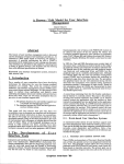
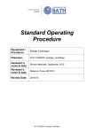
Speed / RCF diagrams for PCR-Rotor 7500 3327
!
100000
#$ !
%# "
& ""
'$
()
%&
speed [rpm]
13000
10000
1000
rmin = 4,7 cm
rmax = 6,8 cm
100
10
100
1000
RCF [x g]
58
10000
12846
100000
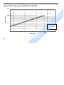
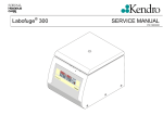
Speed / RCF diagrams for 24 x 2ml Rotor 7500 3328
!
100000
#$ !
%# "
& ""
'$
()
%&
speed [rpm]
13000
10000
1000
rmin = 5,9 cm
rmax = 8,5 cm
100
10
100
1000
RCF [x g]
10000
100000
16060
59
#$ !
%# "
& ""
'$
()
%&
!
U.K./Ireland
USA
All other countries in
Asia Pacific
Kendro Laboratory Products (H.K.) Limited · Hong Kong · Tel. +852 2711 3910 · Fax +852 2711 3858 · [email protected]
Europe, Middle East, Africa
Kendro Laboratory Products International Sales · Hanau · Germany · Tel. +49 (0) 1805-536 376 · Fax +49 (0) 1805-112 114 · [email protected]
Latin America
Kendro Laboratory Products International Sales · Newtown, CT · USA · Tel. +1 203 -270 2080 · Fax +1 203-270 2210 · [email protected]
Internet
http://www.kendro.com
Kendro Laboratory Products GmbH
Postfach 15 63
D-63405 Hanau
Telefon: (+49) 1805 / 536 376
In the interest of continuous product
development, we reserve the right to
make changes without express notice.
20057871
Fresco_uk 09/02
Printed in Germany
!
Denmark
France
Germany
India
Italy
Japan
New Zealand
Poland
Portugal
Spain
Sweden
Switzerland
Kendro Laboratory Products Pty Ltd · Lane Cove, Sydney · NSW 2066 · Tel. +61 (0) 2 -9936 1540 · Fax +61 (0) 2 -9427 9765 · [email protected]
Kendro Laboratory Products GmbH · Vienna · Tel. +43 (0) 1-801 40 0 · Fax +43 (0) 1- 801 40 40 · [email protected]
Kendro Laboratory Products International Sales · Newtown, CT · USA · Tel. +1 203 -270 2080 · Fax +1 203-270 2166 · [email protected]
Kendro Laboratory Products Beijing Rep. Office · Beijing · Tel. +86 (0) 10-6501 3810 · Fax +86 (0) 10-6501 4229 · [email protected]
Kendro Laboratory Products (H.K.) Limited · Hong Kong · Tel. +852 2711 3910 · Fax +852 2711 3858 · [email protected]
Kendro Laboratory Products Shanghai Rep. Office · Shanghai ·Tel. +86 (0) 21-5490 0216 · Fax +86 (0) 21-5490 0230 · [email protected]
Axeb AB · Albertslund · Tel. +45 (0) 43-6246 47 · Fax +45 (0) 43-6246 41 · [email protected]
Kendro Laboratory Products SAS · Courtaboeuf cedex · Tel. +33 (0) 1-69 18 77 77 · Fax +33 (0) 1-60 92 00 34 · [email protected]
Kendro Laboratory Products GmbH · Hanau · Tel +49 (0) 1805-536 376 · Fax +49 (0) 1805-112 114 · [email protected]
Kendro Laboratory Products (India) Pvt. Ltd. · New Delhi · Tel. +91 (0) 11-618 48 40 · Fax +91 (0) 11-618 53 97 · [email protected]
AHSI S.p.A. · Cornate D’Adda · Tel. +39 039-68 271 · Fax +39 039-68 27 500 · [email protected]
Nippon Kendro Co. Ltd. · Tokyo · Tel. +81 (0) 3 -3517 1661 · Fax +81 (0) 3-3517 1664 · [email protected]
Kendro Laboratory Products Pty Ltd · Auckland · Tel. +64 (0) 9 -525 03 33 · Fax +64 (0) 9-525 03 37 · [email protected]
Kendro Spólka z.o.o. · Warsaw · Tel. +48 (0) 22 -663 43 23 · Fax +48 (0) 22-663 43 25 · [email protected]
Heraeus S.A. · Massamá · Tel. +351 (0) 214-387 630 · Fax +351 (0) 214-387 636 · [email protected]
Heraeus S.A. · Madrid · Tel. +34 (0) 91-358 19 96 · Fax +34 (0) 91-358 20 67 · [email protected]
Axeb AB · Sollentuna · Tel. +46 (0) 8 -585 777 50 · Fax +46 (0) 8-623 15 45 · [email protected]
Kendro Laboratory Products AG · Zurich · Tel. +41 (0) 1-454 12 12 · Fax +41 (0) 1-454 12 99 · [email protected]
Kendro Laboratory Products SA · Carouge (Geneva) · Tel. +41 (0) 22 -343 21 67 · Fax +41 (0) 22-342 38 31 · [email protected]
Kendro Laboratory Products PLC · Bishop’s Stortford · Herts · Tel. +44 (0) 1279-827 700 · Fax +44 (0) 1279-827 750 · [email protected]
Kendro Laboratory Products · Newtown, CT · Tel. +1 800 -522 7746 · Fax +1 203-270 2166 · [email protected]
#$ !
%# "
& ""
'$
()
%&
Australia
Austria
Canada
China