1
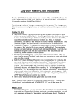
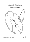
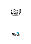
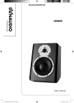
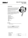
USER MANUAL
TRAINER 201
Dimensions
All dimensions are in millimeters
340
235
196
535
4
5
6
4
7
3
2
9
0
10
5
6
4
7
3
8
1
2
9
0
5
6
7
3
8
1
2
8
1
10
9
0
10
247
©2006-2010 MSS Professional A/S. All rights reserved. No part of this manual may be
reproduced, in any form or by any means, without permission in writing from MSS
Professional A/S, Denmark. Information subject to change without notice. MSS Professional
A/S and all affiliated companies disclaim liability for any injury, damage, direct or indirect loss,
consequential or economic loss or any other loss occasioned by the use of, inability to use or
reliance on the information contained in this document.
P/N 35000180C
Safety information
The following symbols are used to identify important safety information:
Danger! Safety
hazard. Risk of
personal injury.
Danger! Hazardous
voltage. Contact
will cause electric
shock.
Caution! Burn
hazard. Hot
surface. Do not
touch.
Caution! Fire
hazard.
DANGER! This product is not for household use.
Read this manual before operating the machine, follow the safety
precautions listed below, and observe all warnings in this manual
and printed on the machine. Use the machine only as described in
this manual and in accordance with local laws and regulations. Refer
any service operation not described in this manual to a qualified
technician.
If you have questions about how to operate the machine safely, or if you
have followed the instructions in this manual but still believe that the
machine is malfunctioning, please contact MSS Professional on (+44)
1604 839 000 or (+45) 87 400 000.
Preventing electric shocks
• Always ground (earth) the machine electrically.
• The machine may only be connected to AC power via the power cable
supplied with the machine or a replacement supplied and installed by
MSS Professional.
• Use only a source of AC power that complies with local building and
electrical codes, and that has both overload and ground-fault protection.
• Before connecting the machine to power, check that the voltage range
indicated on the machine’s serial label matches your local AC power
voltage. If your AC power voltage is outside the range indicated, do not
use the machine. Contact MSS Professional for assistance.
• Before using the machine, check that all power distribution equipment
and cables are in perfect condition and rated for the current
requirements of all connected devices.
Safety information
3
• If the machine or any cables connected to it are in any way damaged,
defective, wet, or show signs of overheating, stop using the machine
and contact MSS Professional for assistance.
• Disconnect the machine from AC power before refilling or changing the
fluid container, before servicing, and when not in use.
• This machine is water-resistant but not totally waterproof. Do not
immerse in water or any other liquid. Do not expose to high-pressure
water jets.
• Do not spill fluid over the machine. If fluid is spilled, clean the machine
with a damp cloth. If fluid is spilled onto electronic parts, contact MSS
Professional for advice.
• Do not remove the covers or attempt to repair a faulty machine. Refer
any service not described in this manual to MSS Professional.
• Do not operate the machine if any parts are damaged, defective or
missing.
Preventing burns and fire
• The smoke expelled from the output nozzle is hot enough to cause
burns, and very hot droplets of fluid occasionally escape from the nozzle
area. Keep people and objects at least 1 m (40 inches) away from the
nozzle.
• Do not touch the smoke output nozzle area during or after use; it may
stay hot for several hours after the machine has been used.
• Provide a minimum free space of 10 cm (4 inches) around the machine
and ensure free and unobstructed air flow to and around the machine.
• Keep the machine at least 60 cm (24 inches) away from combustible
and heat-sensitive materials.
• Do not attempt to bypass thermostatic switches, fluid sensors or fuses.
• Replace fuses only with ones of the type and rating specified in this
manual and on the machine for the local AC power voltage.
• Do not operate the machine if the ambient temperature (Ta) is below 5°
C (41° F) or above 40° C (104° F).
• Do not operate the machine if the relative air humidity exceeds 80%.
• Do not recycle dense smoke into the machine.
Preventing injuries
• Ensure that the surface on which the machine is installed can safely
hold the weight of the machine.
• Suspending the machine directly over people’s heads is not
recommended. Use smoke ducting instead.
• Do not point smoke output directly at a person’s face or at face height.
• Smoke machines can cause condensation. If smoke concentration is
high for extended periods, floors and surfaces may become slippery.
Wipe dry as necessary to avoid any danger of slipping.
4
Trainer 201 user manual
• Smoke fluid contains food-grade glycols in solution but may present
health risks if swallowed. Do not drink it. Store it securely. If eye contact
occurs, rinse with water. If fluid is swallowed, give water and obtain
medical advice.
Preventing breathing problems
• A smoke machine can operate safely only with the exact type of smoke
fluid it was designed for. Use the machine only with Martin Security
Smoke Trainer Fluid or you may cause the release of toxic gases,
presenting a severe health hazard. You will also probably damage the
machine.
Disposing of this product
MSS Professional products are supplied in compliance with Directive
2002/96/EC of the European Parliament and of the Council of the
European Union on WEEE (Waste Electrical and Electronic Equipment),
as amended by Directive 2003/108/EC, where applicable.
Help preserve the environment! Ensure that this product is recycled at
the end of its life. Your supplier can give details of local arrangements for
the disposal of MSS Professional products.
Safety information
5
Product overview
5
2
6
ON
4
ON
5
7
3
9
10
4
7
3
POWER
ON
6
2
8
1
5
4
2
0
x8
6
9
0
10
5
6
7
3
2
8
1
SPEED
7
8
TIMER
STAND-BY
ON
CYCLE
DELAY
8
1
9
0
10
RUN
9
4
3
1
B
MULTI-FUNCTION
CONTROLLER
A
4
C
ON
STAND-BY
ON
ON
5
4
7
2
9
0
10
POWER
F
ON
6
4
7
2
1
9
0
10
CYCLE
DELAY
G
5
6
3
7
1
9
2
8
OUTPUT
E
5
3
8
1
TIMER
x8
6
3
D
8
0
10
RUN
H I
Machine
Remote control unit
1
2
3
4
5
6
7
8
9
A
B
C
D
E
F
G
6
Output nozzle
Carrying handle
Air vents
Fluid container
Multifunction remote control
READY LED
Power on/off switch
Power cable entry
Main fuseholder
Instant smoke output
Stand-by (set to ON to operate)
Timer value multiplier
Timer engage
Smoke output level
Power indicator
Delay (sets intervals between
output)
H Timer operation indicator
I Output (sets output periods)
Trainer 201 user manual
Contents
Safety information . . . . . . . . . . . . . . . . . . . . . . . . . . . . . . . . . . . . . 3
Product overview . . . . . . . . . . . . . . . . . . . . . . . . . . . . . . . . . . . . . . 6
Introduction . . . . . . . . . . . . . . . . . . . . . . . . . . . . . . . . . . . . . . . . . . . 8
Features . . . . . . . . . . . . . . . . . . . . . . . . . . . . . . . . . . . . . . . . . . . . 8
Installation . . . . . . . . . . . . . . . . . . . . . . . . . . . . . . . . . . . . . . . . . . . . 9
Unpacking . . . . . . . . . . . . . . . . . . . . . . . . . . . . . . . . . . . . . . . . . . 9
Machine location . . . . . . . . . . . . . . . . . . . . . . . . . . . . . . . . . . . . . 9
AC power . . . . . . . . . . . . . . . . . . . . . . . . . . . . . . . . . . . . . . . . . . . 9
Fluid system . . . . . . . . . . . . . . . . . . . . . . . . . . . . . . . . . . . . . . . . 10
Fluid type . . . . . . . . . . . . . . . . . . . . . . . . . . . . . . . . . . . . . . 10
Fluid capacity . . . . . . . . . . . . . . . . . . . . . . . . . . . . . . . . . . . 11
Continuous output and pump ramping . . . . . . . . . . . . . . . . 11
Filling with smoke fluid . . . . . . . . . . . . . . . . . . . . . . . . . . . . 11
Priming the fluid pump . . . . . . . . . . . . . . . . . . . . . . . . . . . . 12
Remote control unit . . . . . . . . . . . . . . . . . . . . . . . . . . . . . . . . . . 12
Ducting . . . . . . . . . . . . . . . . . . . . . . . . . . . . . . . . . . . . . . . . . . . . 13
Operation . . . . . . . . . . . . . . . . . . . . . . . . . . . . . . . . . . . . . . . . . . . . 14
Starting the Trainer 201 . . . . . . . . . . . . . . . . . . . . . . . . . . . . . . . 14
Operating with the remote control . . . . . . . . . . . . . . . . . . . . . . . 15
Basic service . . . . . . . . . . . . . . . . . . . . . . . . . . . . . . . . . . . . . . . . . 16
Fluid system . . . . . . . . . . . . . . . . . . . . . . . . . . . . . . . . . . . . . . . . 16
Fluid filter . . . . . . . . . . . . . . . . . . . . . . . . . . . . . . . . . . . . . . 16
Cleaning . . . . . . . . . . . . . . . . . . . . . . . . . . . . . . . . . . . . . . . . . . . 16
Replacing a fuse . . . . . . . . . . . . . . . . . . . . . . . . . . . . . . . . . . . . 17
Troubleshooting . . . . . . . . . . . . . . . . . . . . . . . . . . . . . . . . . . . . . . 18
Trainer 201 specifications . . . . . . . . . . . . . . . . . . . . . . . . . . . . . . 19
Introduction
The Trainer 201 from MSS Professional is a versatile smoke and fog
generator for professional use. It can produce a variety of effects from an
optically translucent haze to a dense ‘white-out’ that very effectively
simulates dense smoke for realistic firefighter training. The powerful output
makes the Trainer 201 highly suitable for distributing smoke via ducting.
The Trainer 201 has been designed to cope with the rigors of training, with
a tough outer casing and rugged water-resistant design.
A total fluid capacity of 2.5 liters (5.3 US pints/4.4 Imp. pints) ensures
good autonomy between refills.To allow safe and reliable operation, a
direct ceramic thermal cutout system shuts down the machine in the event
of overheating.
The Trainer 201 is controlled using a multifunction cable remote control
unit that is supplied with the machine. The remote can be conveniently
fastened in an onboard docking station.
Details of the full range of MSS Professional training products are
available on the MSS Professional website at: http://www.trainingsmoke.com.
Features
The Trainer 201 features:
• Multifunction cable remote control (supplied) with instant or timercontrolled output and onboard docking station
• Variable smoke output level up to 500 cubic meters (17 600 cubic ft.) per
minute
• 1kW heat exchanger, giving high output from a compact vaporizing
system
• DTP direct ceramic overheat protection
• 2.5 liters (5.3 US pints/4.4 Imp. pints) onboard fluid capacity
• High power piston pump
• Pump ramping for continuous output
• Heavy duty construction
• Water resistant design
• Optional 4 inch smoke ducting adaptor kit
8
Trainer 201 user manual
Installation
DANGER! Do not try to install the Trainer 201 until you have read and
observed all the precautions listed in “Safety information” on page
3.
Unpacking
Unpack and check the machine.
The Trainer 201 is supplied with:
• Multifunction remote control with 6 m (19.5 ft.) cable
• 2.5 liters (5.3 US pints/4.4 Imp. pints) smoke fluid container
• Power cable (a suitable power plug must be supplied by the user)
Machine location
The Trainer 201 must be placed securely on a level, stable surface that
can safely support its weight. Installing the machine above people’s heads
is not recommended. If smoke output above ground level is required, the
easiest solution is to use flexible smoke ducting.
Ensure that there is a minimum free space of 10 cm (4 inches) around the
machine, unobstructed air flow around the machine, minimum 1 m (40
inches) free space in front of the nozzle and a minimum distance of 60 cm
(24 inches) to combustible materials (wood, paper, etc.).
AC power
The Trainer 201 is available in two models:
• The 115 V model accepts 110-120 V, 60 Hz nominal AC power
• The 230 V model accepts 220-240 V, 50 Hz nominal AC power
Both models are supplied with a 2 meter (6.5 ft.) power cable. Before
using the machine, a grounding-type (earthed) power plug that fits the
local power outlets must be obtained locally and installed on the power
cable.
Installation
9
DANGER! Make sure the power plug is correctly rated:
• 115 V models must be fitted with a plug rated 15 amp minimum
• 230 V models must be fitted with a plug rated 6.3 amp minimum
When installing the plug, follow the plug manufacturer’s instructions and
connect pins as follows: yellow and green wire to ground (earth), blue wire
to neutral and brown wire to live.
The table below shows some common pin identification schemes.
Wire
Pin
Marking
Screw color
brown
live
“L”
yellow or brass
blue
neutral
“N”
silver
yellow/green
ground (earth)
green
Before connecting the Trainer 201 to power, check that the voltage range
indicated on the machine’s serial label matches your local AC power
voltage. If your AC power voltage is outside the range indicated, do not
use the machine. Contact MSS Professional for assistance.
Fluid system
D A N G E R ! A smoke machine can run safely only on the specific
smoke fluid or fluids it is designed for. Use ONLY Martin Security
Smoke Trainer Fluid in the Trainer 201. NEVER operate the machine
with any other type of fluid, or toxic gas may be produced. You will
probably also cause damage to the machine that is not covered by
the product warranty.
Fluid type
The type of fluid used affects the density and persistence of the smoke
produced. Two fluids are compatible with the Trainer 201:
• Martin Security Smoke Trainer Fluid Medium gives a medium-density
smoke with medium persistence, and is suitable for general use.
• Martin Security Smoke Trainer Fluid Heavy gives a higher density
smoke with higher persistence. This fluid is suitable for large areas and
where maximum smoke density is required.
10
Trainer 201 user manual
Fluid capacity
Important!
Check the fluid level regularly. Do not allow the Trainer 201 to run
out of fluid. Attempting to operate the machine with no fluid may
cause damage that is not covered by the product warranty.
The Trainer 201 has an on-board container with a capacity of 2.5 liters
(5.3 US pints/4.4 Imp. pints), giving approximately 1 hour 20 minutes of
continuous operation at full output. Maximum continuous operation time
and maximum continuous output level vary slightly at different input
voltages.
C o n t i n u o u s o ut p u t a nd p u m p r a m p i n g
The Trainer 201 uses a technique called 'pump ramping' to allow
continuous smoke output during the entire operation period. When the
output level is set to maximum, the machine gives maximum output for
approximately 1 minute, until the heat exchanger has used its energy
reserves. The pump ramping system then reduces the output level,
overriding the output level setting, for the rest of the operation period. This
system ensures that output is continuous.
F i l l i n g w i t h s mo k e f l u i d
Important! Keep smoke fluid and all components in the fluid system
free of dust, dirt, fluff and any form of contamination.
Do not shake or vibrate the fluid container or machine, as this will
create air bubbles in the fluid. Excessive bubbles impair
performance and may cause damage to the heat exchangers that is
not covered by the product warranty.
To fill the Trainer 201 with smoke fluid:
1. Isolate the Trainer 201 from power.
2. Fit a full container of Martin Security Smoke Trainer Fluid into the fluid
compartment and remove its cap.
3. Check that fluid and all components are totally free of dirt, fluff and
other small particles. Impurities will clog the machine and make service
or repair necessary.
4. Install the Trainer 201’s fluid adaptor cap complete with fluid lines
tightly on the fluid container, ensuring that the suction tube reaches the
bottom of the container.
5. When using the machine for the first time or after fluid containers have
been changed, prime the pump (see below).
Installation
11
Priming the fluid pump
When using the machine for the first time or after fluid containers have
been changed, the fluid pump must be primed. To prime the pump:
1. Apply power and allow the machine to warm up.
2. When the READY LED on the machine lights, turn the OUTPUT knob
on the remote control fully clockwise to set the machine to maximum
output.
3. Use the FOG button to fire the machine for approximately 10 seconds
or until smoke is produced at the output nozzle.
If smoke is not produced within 20 seconds, there may be a problem with
the fluid system. Refer to “Troubleshooting” on page 18 for fault-finding
procedures.
Remote control unit
The Trainer 201 is supplied with a cable remote control unit connected and
secured with two thumbscrews in its on-board docking station.
The remote is connected to the Trainer 201 via a hard-wired 6m (19.5 ft.)
cable and 3-pin XLR connector. A longer cable can be fitted, up to a
maximum cable length of 25 m (82 ft). Standard microphone cable can be
used. The pin configuration of the remote connection is:
• Pin 1: Ground
• Pin 2: +16 V output from machine
• Pin 3: 0 - 10 V input to machine
12
Trainer 201 user manual
Power the Trainer 201 off before disconnecting or connecting the remote
control unit.
Ducting
The optional smoke ducting adaptor available from MSS Professional
allows the Trainer 201 to be connected to standard 100 mm (4-inch)
flexible smoke ducting. The adaptor allows air to mix with the smoke
output before it enters the ducting.
DANGER! Do not use any other method than the MSS Professional
ducting adapter to connect smoke ducting to the Trainer 201, or you
may cause moisture buildup with a risk of electric shocks or damage
to the machine that is not covered by the product warranty.
Good results are obtained with smoke ducting up to 20 m (65 ft.) total
length.
Avoid sharp bends as far as possible, as these encourage condensation.
Ensure free and unobstructed airflow to the space between the output
nozzle and the entry to the smoke ducting.
Installation
13
Operation
DANGER! Do not try to operate the Trainer 201 until you have read
and observed all the precautions listed in “Safety information” on
page 3.
IMPORTANT! Do not allow the Trainer 201 to run out of fluid, as this
may cause serious damage to the product that is not covered by the
warranty.
Starting the Trainer 201
Before operating, check that the Trainer 201 is correctly and safely
installed, that the fluid container is filled with enough fluid (see “Fluid
system” on page 10), and that the remote control is connected.
To start the Trainer 201 from a ‘cold’ state:
1. Connect the Trainer 201 to power, and switch on at the power switch on
the machine.
2. Set the Standby switch on the remote control to ON.
3. The remote control becomes functional when the READY LED on the
back of the Trainer 201 lights after approximately 7 minutes warm-up
time.
If you are starting the machine for the first time or after the fluid has been
changed, the pump may need to be primed. Do this by setting OUTPUT to
maximum and firing the machine for 10 seconds or until smoke is
produced.
14
Trainer 201 user manual
Operating with the remote control
MULTI-FUNCTION
CONTROLLER
The Trainer 201 can be controlled using the multifunction cable remote as
described below:
4
ON
STAND-BY
ON
ON
5
4
7
2
1
5
9
10
OUTPUT
4
7
2
POWER
ON
6
3
8
0
x8
6
3
TIMER
9
0
10
DELAY
6
7
1
9
2
8
1
5
3
CYCLE
8
0
10
RUN
A – ON: When the machine has reached operating temperature, press
and hold this button to produce instant smoke output.
B – STAND-BY: Puts the machine into standby mode. Switch to ON for
warm-up and operation.
C – TIMER x8 When using the timer, increases timer values by a factor of
8, so that for example a 5 second run time becomes 40 seconds and a 10
second delay time becomes 1 minute 20 seconds.
D – TIMER ENGAGE: Engages the timer to produce smoke according to
the OUTPUT, DELAY and RUN settings.
E – OUTPUT: Turn clockwise to increase smoke output, Turn fully
counter-clockwise for zero output.
F – POWER: This LED lights when the machine is switched on.
G – DELAY: Turn clockwise for longer intervals between smoke output
periods when the timer is engaged.
H – CYCLE: This LED lights when the timer is engaged and the machine
is operating.
I – RUN: Turn clockwise for longer smoke output periods when the timer is
engaged.
Operation
15
Basic service
DANGER! Do not try to service the Trainer 201 until you have read
and observed all the precautions listed in “Safety information” on
page 3.
Any service not described in this section must be carried out by a service
technician authorized by MSS Professional. Please refer to MSS
Professional for assistance with obtaining service.
Fluid system
DANGER! Use ONLY Martin Security Smoke Trainer Fluid in the
Trainer 201. NEVER operate the machine with any other type of fluid,
or toxic gas may be produced. You will probably also cause damage
to the machine that is not covered by the product warranty.
For general information about the fluid system, see “Fluid system” on page
10.
For instructions for filling the Trainer 201 with smoke fluid, see “Filling with
smoke fluid” on page 11.
F l uid f i lt er
The Trainer 201 uses a washable filter on the end of the smoke fluid
suction tube. Check that the filter is perfectly clean each time you change
or refill the smoke fluid container.
If the filter is dirty or contaminated, wash in clean water until perfectly
clean or replace with a new item.
Cleaning
Excessive dust, smoke fluid, and dirt buildup will degrade performance
and cause overheating and damage to the machine that is not covered by
the product warranty. To maintain adequate cooling, dust must be cleaned
from the outer casing and air vents periodically.
Isolate the machine from power and allow to cool completely before
cleaning. The nozzle area can remain hot for several hours after use.
• Remove dust from the air vents on the side of the outer casing with a
soft brush, cotton swab, vacuum, or compressed air.
• Clean the outer casing with a damp cloth only.
16
Trainer 201 user manual
• Ensure that the nozzle area ia completely cool, then wipe up any smoke
fluid residue from the nozzle and surrounding area with a damp cloth.
Replacing a fuse
DANGER! Disconnect the machine from AC power before removing
or installing a fuse. Never attempt to bypass a fuse or replace a fuse
with one of a different type and/or rating. If a new fuse blows shortly
after it is installed, stop using the machine and contact MSS
Professional for assistance.
If the main on/off switch and the power LED on the remote do not light
when power is applied, the main fuse may have blown. To replace the
fuse:
1. Isolate the machine from power and allow to cool.
2. Use a flat-headed screwdriver to open the main fuseholder next to the
power cable entry.
3. Replace the main fuse with one of the same type and rating only (see
“Electrical” on page 20 for fuse details).
4. Reinstall and tighten the fuseholder before reapplying power.
Basic service
17
Troubleshooting
Problem
No fog output when the
machine is fired using the
FOG ON or TIMER
functions
Machine is not ready after 7
minutes heating time
Fog disperses too quickly
POWER LED on remote
does not light when power is
applied, and smoke cannot
be produced.
18
Probable cause(s)
Suggested remedy
Machine is not ready
Allow time to warm up
Fluid is below minimum
level
Add fluid
Standby switch is OFF
Set Standby to ON
Timer on period (RUN) is
set to level 0
Set RUN to at least level 1
Standby switch is OFF
Set Standby to ON
Electrical malfunction
Refer to MSS Professional
Density level too low
Increase OUTPUT setting
on multifunction remote
Remote control not correctly
connected
Check connection
Power not correctly
connected
Check connection
Main fuse blown
Replace
Electrical malfunction
Refer to MSS Professional
Trainer 201 user manual
Trainer 201 specifications
Physical
Dimensions (L x W x H) . . . . . . . . . . . . . . 500 x 225 x 165 mm (20 x 9 x 6.6 in.)
Shipping dimensions (L x W x H). . 670 x 310 x 300 mm (26.4 x 12.2 x 11.9 in.)
Weight (without fluid) . . . . . . . . . . . . . . . . . . . . . . . . . . . . . . . . . . .11 kg (24.2 lb.)
Weight (with fluid) . . . . . . . . . . . . . . . . . . . . . . . . . . . . . . . . . . . 13.5 kg (29.8 lb.)
Performance
Maximum smoke output. . . . . . . . 500 cubic meters (17 600 cubic ft.) per minute
Maximum operating time at full output . . . . . . . . . . . . Approx. 1 hour 20 minutes
Operating time . . . . . . . . . . . . . . .Continuous, automatic output level adjustment
Warm-up time . . . . . . . . . . . . . . . . . . . . . . . . . . . . . . . . . . . . . Approx. 7 minutes
Control
Multifunction cable remote, 0-10 V analog
Instant smoke, stand-by, timer X8 and timer engage push-buttons
LED power and timer cycle indicators
Independent output level, timer delay and timer runtime controls
Timers: 2 - 144 sec.delay, 2 - 144 sec. runtime
Installation
Minimum clearance in front of output nozzle . . . . . . . . . . . . . . . 1 m (40 inches)
Minimum free space around machine . . . . . . . . . . . . . . . . . . . . 10 cm (4 inches)
Minimum distance to combustible materials . . . . . . . . . . . . . . 60 cm (24 inches)
Orientation . . . . . . . . . . . . . . . . . . . . . . . . . . . . . . . Maximum 30° from horizontal
Minimum ambient temperature . . . . . . . . . . . . . . . . . . . . . . . . . . . . . 5° C (41° F)
Maximum ambient temperature . . . . . . . . . . . . . . . . . . . . . . . . . . . 40° C (104° F)
Heat exchanger
Heater . . . . . . . . . . . . . . . . . . . . . . . . . . . . . . . . . . . . . . . . . . . . . 1 kW (at 240 V)
Thermal protection . . . . . . . . . . . . . . . . . . . . . . Direct ceramic thermal trip device
Temperature control . . . . . . . . . . . . . . . . . . . . . . . . . . . Electronic (thermocouple)
Fluid system
Approved fluid . . . . . . . . Martin Security Smoke Trainer Fluid, Medium or Heavy
On-board fluid capacity . . . . . . . . . . . . . . . 2.5 liters (5.3 US pints/4.4 Imp. pints)
Fluid consumption at max. continuous output . . . . . . . . . . . . . . 75 ml per minute
Fluid pump . . . . . . . . . . . . . . . . . . . . . . . . . . . . . . . . . . . . . .Piston, high pressure
Pump startup . . . . . . . . . . . . . . . . . . . . . . . . . . . . . . . . . . . . Soft start electronics
Electrical
115 V model
AC power . . . . . . . . . . . . . . . . . . . . . . . . . . . . 110-120 V, 60 Hz nominal
Power and current* . . . . . . . . . . . . . . . . . . . . . . . . . . . . . 1070 W, 9.72 A
Main fuse. . . . . . . . . . . . . . . . . . . . . . . . . . . . . T 15 A (slow blow), 250 V
230 V model
AC power . . . . . . . . . . . . . . . . . . . . . . . . . . . . 220-240 V, 50 Hz nominal
Power and current* . . . . . . . . . . . . . . . . . . . . . . . . . . . . . 1070 W, 4.45 A
Main fuse. . . . . . . . . . . . . . . . . . . . . . . . . . . . .T 6.3 A (slow blow), 250 V
*At nominal voltage. Your local voltage may fluctuate. Allow for +/- 10% variation.
Connections
Power inlet . . . . . Hard-wired grounding (earthed) 2 m (6.5 ft.) cable tail w/o plug
Cable remote control connection . . . . . . . . . . . . . . . . . . . . . . . . . . . . . .3-pin XLR
Ducting. . . . . . . . . . . . . . . . Optional adaptor for 100 mm (4 inch) flexible ducting
Approvals
This product meets the requirements of the following EC Standards, and as such
complies with the EMC and LVD directives of the European Community:
European EMC: . . . . . . . . . . . . . . . . EN 50 081-1, EN 55 014,
EN 55 022 /B, EN 60 555
European safety: . . . . . . . . . . . . . . . . . . . . . . . . . EN 60 335-1
Immunity: . . . . . . . . . . . . . EN 50 082-1, IEC 801-2, IEC 801-4
Included Items
Multifunction remote control with 6 m (19.5 ft.) cable
Accessories
2.5 liter container, MSS Professional Trainer Fluid Medium . . . . . P/N 97121223
2.5 liter container, MSS Professional Trainer Fluid Heavy. . . . . . . P/N 97121226
9.5 liter container, MSS Professional Trainer Fluid Medium . . . . . P/N 97121224
9.5 liter container, MSS Professional Trainer Fluid Heavy. . . . . . . P/N 97121227
25 liter container, MSS Professional Trainer Fluid Medium . . . . . . P/N 97121225
25 liter container, MSS Professional Trainer Fluid Heavy . . . . . . . P/N 97121228
MSS ducting system incl. 5 m of 100 mm (4-inch) ducting . . . . . . P/N 92622024
Ordering information
Trainer 201, 115 V, 60 Hz . . . . . . . . . . . . . . . . . . . . . . . . . . . . . . . P/N 92256110
Trainer 201, 230 V, 50 Hz . . . . . . . . . . . . . . . . . . . . . . . . . . . . . . . P/N 92256100
Specifications subject to change without notice.
Supplier
MSS Professional A/S
MSS Professional Ltd.
Brunbjergvej 6
8240 Risskov
Denmark
Tlf.: +45 72 170 011
Fax: +45 86 170 055
www.training-smoke.com
Rectory Court, High Street
Kislingbury
Northampton
Northamptonshire
NN7 4AG
England
Tel: +44 01604 839000
Fax: +44 01604 832666