1
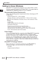
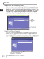
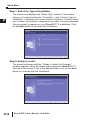
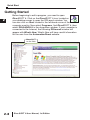
QUICK START
CHAPTER
2
In This Chapter:
Getting to Know Windows . . . . . . . . . . . . . . . . . . . . . . .2-2
Installation of DirectSOFT 6 . . . . . . . . . . . . . . . . . . . . .2-3
Getting Started . . . . . . . . . . . . . . . . . . . . . . . . . . . . . . .2-8
Welcome to DirectSOFT100 . . . . . . . . . . . . . . . . . . . .2-12
Begin Editing a Program . . . . . . . . . . . . . . . . . . . . . . .2-14
Establish the Communication Link . . . . . . . . . . . . . . .2-24
Monitor the Program . . . . . . . . . . . . . . . . . . . . . . . . . .2-30
Quick Start
1
Getting to Know Windows
2
3
D
5
6
7
8
9
1
11
2
13
4
A
B
C
D
2-2
DirectSOFT 6 Programming Software runs under 32-bit or 64-bit
Windows operating systems (XP/Vista/7/8/8.1). It’s a good idea to
understand the operating system for your computer.
Recommended System Requirements
Check the following system requirements when choosing your PC
configuration.
• Pentium/Celeron CPU, 1 Ghz or greater
• Windows XP(Home and Pro)/Vista/7/8/8.1, 32-bit or 64-bit versions.
NO DOS, OS/2, Macintosh, XP 64-bit, Linux or Unix versions or 16-bit
versions
• 512Mb RAM
• 50Mb available hard drive disk space.
• CD-ROM or DVD drive
• At least one unused serial communications port,
USB with USB-to-serial adapter, 10base-T or 10/100
Ethernet Network Card when using Hx-ECOM or Hx-ECOM100
• 1024 x 768 resolution color SVGA monitor
Power Supply
It is recommended that the computer which DirectSOFT 6 operates
on has some form of power surge protection. A quality surge
protector will protect your computer from most surges and spikes;
however, an uninterruptible power supply (UPS) will provide the
best protection. A UPS provides isolation between the AC power
source and the computer. It also has a battery backup for blackout
and brownout conditions.
DirectSOFT 6 Package Contents
Now is the time to review the contents of your DirectSOFT 6
software package. you should have the following items:
• CD ROM
• Programming User Manual
DirectSOFT 6 User Manual, 1st Edition
Installation of DirectSOFT 6
Quick Start
Step 1: Load the CD
DirectSOFT 6 Programming Software for DirectLOGIC PLCs is
available on the AutomationDirect CD. To install DirectSOFT 6,
insert the AutomationDirect CD into your PC’s CD drive. Select
“Open folder..” when autoplay dialog appears, or navigate to the
CD drive, and select the SetupDS6 executable.
Step 2: Exit all other Windows Applications
The dialog below issues a reminder to exit all other Window
applications. If you are unsure of the programs that may be
running, open the Task Manager by pressing the Ctrl-ALT-Delete
keys at the same time. Close any opened applications by selecting
them and clicking on the Close button of the Task Manager. Click
on the OK button to proceed with the installation.
DirectSOFT 6 User Manual, 1st Edition
1
2
3
D
5
6
7
8
9
0
1
2
3
4
A
B
C
D
2-3
Quick Start
Step 3: Enter the Product Key Code
From this window, enter the Product Key that was e-mailed to you
(or the one who purchased the software), or phone 1-800-633-0405
and get the Product Key from either sales or technical support if you
did not receive it. This software package is protected by this Product
Key code. Only licensed users that have a Product Key code may
install the software. Enter the Product Key using all caps and any
dashes shown then click the Next button.
1
2
3
D
5
6
7
8
9
1
11
2
13
4
A
B
C
D
Enter
Product Key
here
Then click on
the Next button
Step 4: Installing an Upgrade
If you are installing the DirectSOFT 6 upgrade version, setup will
search your PC to look for a previous version of DirectSOFT. If a
previous DirectSOFT version is not found, you will be prompted to
enter a valid product key code from a previous version of DirectSOFT.
Click here to proceed with
the DirectSOFT 6 installation
2-4
DirectSOFT 6 User Manual, 1st Edition
Step 5: License Agreement
Quick Start
The wizard displays the “Software License Agreement” shown
below. Read the agreement and select I accept the terms of the
license agreement. Click Next to continue with the installation. If
you do not accept the license agreement, cancel the installation.
Click here if you agree with the
License Agreement’s terms.
Step 6: Enter the Customer Information
The “Customer Info” window requests the user name and
company. Enter the name of the person assigned to the
DirectSOFT 6 Programming Software and the name of your
company. Click the Next button to continue with the DirectSOFT 6
installation.
DirectSOFT 6 User Manual, 1st Edition
1
2
3
D
5
6
7
8
9
0
1
2
3
4
A
B
C
D
2-5
Quick Start
Step 7: Select the Type of Installation
1
2
3
D
5
6
7
8
9
1
11
2
13
4
A
B
C
D
2-6
The wizard now displays the “Setup Type” window. This window
allows you to select either the “Complete” or the “Custom” type of
installation. Complete is the most common selection. Custom allows
you to select the optional components you want. It is recommended
that you select Complete for your DirectSOFT 6 installation. Click
on the Next button to proceed with installation.
Step 8: Ready to Install
The wizard continues with the “Ready to Install the Program”
window appears. Verify the folder name where the DirectSOFT 6
files are to be stored. If this is the desired folder, click on the Next
button to continue with the installation.
DirectSOFT 6 User Manual, 1st Edition
Quick Start
The following window lets you know that the DirectSOFT 6
Programming Software is being installed onto your computer.
1
Step 9: Installation is Complete
The wizard now displays the “InstallShield Wizard Complete”
window shown below. Click on the Finish button.
If an Upgrade
If an older DirectSOFT version is found during the installation, you
will be prompted to make DirectSOFT 6 the default projects folder.
You will then be asked if you want the existing projects copied to
the DirectSOFT 6 projects folder.
DirectSOFT 6 User Manual, 1st Edition
2
3
D
5
6
7
8
9
0
1
2
3
4
A
B
C
D
2-7
Quick Start
1
Getting Started
2
3
D
5
6
7
8
9
1
11
2
13
4
A
B
C
D
2-8
Before beginning to edit a program, you need to open
DirectSOFT 6. Click on the DirectSOFT 6 icon located on
your desktop screen to open the DSLaunch window. You
can also click on Start located in the left-hand corner of the
computer monitor. Now select Programs, find DirectSOFT 6, then
select DSLAUNCH 6 in the drop-down window. If your computer is
connected to the Internet, the following DSLaunch window will
appear with What’s New. What’s New will have useful information
for the user from the AutomationDirect website.
DirectSOFT
on the Web
DirectSOFT 6 User Manual, 1st Edition
Quick Start
If your computer is not connected to the Internet at the time of
launching DirectSOFT 6, the DSLaunch window will display a
message stating that the website is not available. This is okay. It
isn’t necessary to be on the Internet each time that DSLaunch is
opened. Our website can be accessed anytime the computer is
connected to the Internet by double-clicking DirectSOFT on the
Web.
DirectSOFT 6 User Manual, 1st Edition
1
2
3
D
5
6
7
8
9
0
1
2
3
4
A
B
C
D
2-9
Quick Start
The main DSLaunch window is opened by selecting DirectSOFT 6
Programming located in the Applications section of the Menu
Tree. The launch window will then appear as follows.
1
2
3
D
5
6
7
8
9
1
11
2
13
4
A
B
C
D
Utilities, such
as NetEdit3
DirectSOFT
Programming
Installed
Support
Communication
Links to PLCs
2-10
Windows-type
Menu Tree
From this window, additional utilities, such as, NetEdit, CTRIO WB,
etc., can all be launched from one central location. This is also used
to create and manage PLC programs and the communications links
between your personal computer and the PLC.
Notice the different areas which are pointed out in the launch
window.
NOTE: Also see DSLAUNCH comments in Chapter 3.
DirectSOFT 6 User Manual, 1st Edition
Quick Start
If you have been using previous versions of DirectSOFT
Programming Software, you will see that the DSLaunch window
looks much like it has for many years. Descriptions of the various
sections are as follows:
• Applications 앥 These are the applications currently installed in
DirectSOFT 6. They are visible in the Menu tree under the
Applications folder/icon and are linked to applications that have
been designed for launch from DirectSOFT 6. For example, to
create a new program, double-click the DirectSOFT 6
Programming name.
• Utilities 앥 Several utilities are available under this folder/icon. If
you have already installed available utilities, such as, NetEdit,
CTRIO Workbench, etc., these will be shown here. Shortcuts to
your favorite utilities can also be added by adding them to the
Utililities section of the DS600.ini file.
• Projects 앥 These are the programs which are created in
DirectSOFT 6. A project is the collective name for your program
and all of its documentation. When you create a new project or
work on an existing project, you will see it listed in the Menu
Tree under the Projects folder/icon by name. To open an
existing project, double-click on the project name. To open a
project not listed, right-click on Projects and select Browse to
locate the project, then select it.
• Comm Links 앥 This is for the communication links used to
connect from your PC to one or more of your PLCs. If there were
Comm Links existing in your previous version of DirectSOFT,
they will appear here. New Comm Links will also appear here
after they are setup.
The remainder of this chapter will be devoted to the following:
1. Create a new program.
2. Add some rungs.
3. Document the elements and rungs.
4. Connect to a PLC.
5. Download to a PLC.
6. Monitor the program and change status.
DirectSOFT 6 User Manual, 1st Edition
1
2
3
D
5
6
7
8
9
0
1
2
3
4
A
B
C
D
2-11
Quick Start
1
Welcome to DirectSOFT100
2
3
D
5
6
7
8
9
1
11
2
13
4
A
B
C
D
NOTE: If you have purchased the full version of DirectSOFT 6, go to page
2-14, Begin Editing a Program.
If you have loaded the free version of DirectSOFT 6, you should
know what you can and cannot do with the software.
What is DirectSOFT100?
2-12
The DirectSOFT100 software is provided as a solution for small
applications and to assist in your decision to purchase the full
DirectSOFT 6 programming software. There are, of course,
limitations to the use of DirectSOFT100. The following is what you
can and cannot do with the software:
• You CAN create a program from scratch, and it can be as large as you
want it to be.
• You CAN save programs larger than 100 words to disk, but you CANNOT
write it to the PLC.
• You CAN convert DirectSOFT100 version to the full version if you
purchase the key and enter the key code in the DirectSOFT100
dialog (it may appear often) or in the Help > About dialog.
• You CANNOT download a program to a PLC larger than 100 words.
• You CANNOT open an offline project larger than 100 words.
• You CANNOT open a program in the PLC larger than 100 words.
There are no other limitations. DirectSOFT100 is able to use all of
the features described in this manual. Many instances of
DirectSOFT100 can be running at one time and monitor any
number of data points. DirectSOFT100 is basically the same,
functionally, as DirectSOFT 6 (full version) except the ladder
program needs to remain within 100 words.
DirectSOFT 6 User Manual, 1st Edition
Using DirectSOFT100?
Quick Start
To begin a project, double-click on DirectSOFT 6 Programming
under Applications on the menu tree. The following Welcome to
DirectSOFT100 window will appear.
Click here to
begin a project.
Click on Run DirectSOFT100 and the New Project dialog will
open as shown on page 2-14. You can now begin to edit a
program following from Step 1.
DirectSOFT 6 User Manual, 1st Edition
1
2
3
D
5
6
7
8
9
0
1
2
3
4
A
B
C
D
2-13
Quick Start
1
Begin Editing a Program
2
3
D
5
6
7
8
9
1
11
2
13
4
A
B
C
D
You can now begin editing your program. The following steps will
show you the basics of editing with DirectSOFT 6. This will not be
an attempt to teach you how to develop a control program, but it will
give you the basics to get started using DirectSOFT 6 so that you
can edit a program.
Step 1: Start a New Project
2-14
To begin a new project, double-click DirectSOFT 6 Programming
under Applications in the menu tree. The following window will
appear. The New Project window is used to enter the basic
information to begin a new project. Name the new project, then
move the cursor to the Family area and select the PLC family to
match the PLC that you are using. Next, select the CPU type. Once
all of the information has been entered, click on OK. Keep in mind
that the available mnemonics, processing rules and the tool bar
characteristics are tailored to the Family and Type selections that
you make.
New Project window
...click on OK
Type a new name
Select the PLC Family
DirectSOFT 6 User Manual, 1st Edition
Select the CPU Type
Quick Start
After clicking on OK, the next window to appear is the Ladder View
with a Tip of the Day dialog box as seen below. The Tip of the Day
dialog will appear each time a new project is started, and each
time an existing project is opened. If it is not desired to have this
dialog “pop-up” as mentioned, simply click off the check mark
preceding “Show tips at startup”. The tips dialog can always be
opened by clicking on Help > Tip of the day on the main menu
bar. More tips can be read by clicking on the Next button. After
clicking on the Close button the new Program display window will
be totally in view.
Show tips at startup
Regular users of DirectSOFT will note that the new programming
window looks a bit different than previous DirectSOFT
programming software. The “Online” and “Offline” toolbars have
the same layout as previous DirectSOFT programming windows
but a crisp new look for the button icons. Notice that some of the
toolbar icons are grayed-out and some of the icons are not. The
available icons in the online toolbar will be visible. As a program is
edited, more of the grayed-out icons will become visible. The online
toolbar is grayed-out and will remain this way until the PC is
connected to the PLC. See Chapter 4 for more toolbar features.
DirectSOFT 6 User Manual, 1st Edition
1
2
3
D
5
6
7
8
9
0
1
2
3
4
A
B
C
D
2-15
Quick Start
Offline
Toolbar
1
2
3
D
5
6
7
8
9
1
11
2
13
4
A
B
C
D
2-16
Online
Toolbar
Push-pin
Edit Mode
buttons
Cursor
Ladder Palette Bar
By default, there are two windows that will be in view when a new
project is opened. One is the Cross Reference View on the left and
the other is the Ladder View on the right. The Cross Reference
View is one of the dockable views in DirectSOFT 6 which also
includes Data Views and the Output window. These views can be
docked to any edge of the Programming Window or they can be
undocked and “float” to any part of the screen, even onto a different
display if you have multiple monitors. If the view is docked, you can
“auto-hide” the view by clicking on the push-pin in the upper righthand corner of the view. The view will auto-hide to the left of the
Ladder View with the name of the view on the tab. To bring the view
from auto-hide, hold the mouse cursor over the name in the tab. If
the view is not needed, click on the X located to the right of the
push-pin to close the view. See Chapter 7 to learn more about
views.
Notice the Ladder Palette Bar located to the right of the Ladder
View. The element buttons are grayed-out unless the Edit Mode has
been activated. To activate the Ladder Palette, click on either EDIT
Mode button; one is located on the Offline toolbar and one is
located at the top of the Ladder Palette. This palette can be
repositioned anywhere on the screen by “grabbing” it with the
mouse pointer at the top of the palette and dragging it to a new
position. The Ladder Palette contains the buttons that access the
rung elements and operations commonly used when editing ladder
logic programs.
DirectSOFT 6 User Manual, 1st Edition
Quick Start
The diagram below shows a newly opened Display window with the
Cross Reference View in the auto-hide position and the Ladder
View in full view.
Cross Reference View
in auto-hide position
It is good practice to leave the Cross Reference View open while
editing your program. The rung elements are added to the Cross
Reference View as the program is accepted.
Accepting a program will be discussed later in this chapter.
NOTE: The Cross Reference View can be retrieved by going to View on
the Menu Bar and select it from the drop-down menu, then click on the
push-pin to keep it in view.
Step 2: Select Edit Mode
The ladder View has two viewing modes; the Display Mode and
the Edit Mode. When a new program or an existing program is
opened, the Ladder View will be in the Display Mode which is only
a viewing mode. A program cannot be edited in this mode. In order
to edit a program, you must be in the Edit Mode. To enable the
Edit Mode, either click on the Edit Mode button on the Offline
toolbar or click on the Edit Mode button on the Ladder Palette Bar.
You will know when the Edit Mode is active when the cursor box
becomes solid, a box appears around the Edit Mode buttons and
the elements in the Ladder Palette are highlighted (see diagram on
the next page).
DirectSOFT 6 User Manual, 1st Edition
1
2
3
D
5
6
7
8
9
0
1
2
3
4
A
B
C
D
2-17
Quick Start
1
2
3
D
5
6
7
8
9
1
11
2
13
4
A
B
C
D
Edit Mode
(solid cursor box)
The Ladder Palette (shown below) may not be exactly like the one
you have on your computer screen. The elements shown in the
palette will depend on which CPU your PLC is using. This example
shows the elements common to most of the CPUs.
Edit Mode
Accept
Not Equal to
Contact
2-18
Equal to/or
Greater Than
Contact
Normally Closed
Immediate
Negative
Contact
Differential
Contact
Normally Open
Positive
Equal to
Immediate
Differential
Contact
Contact
Contact
Normally
Closed Contact
Normally Open
Contact
Less Than
Contact
Browse
Coils
Browse
Contacts
Browse
Boxes
DirectSOFT 6 User Manual, 1st Edition
Wire to Output
Browse
Elements
Wrap Wire to
Stage
Quick Start
Step 3: Enter an Input Element
Use the Ladder Palette to enter the first instruction of the program.
First, click on one of the Edit Mode buttons to begin to edit your
program. The rectangular edit cursor will change to a solid color.
The edit cursor should be positioned to the far left on Rung 1. Your
first entry can be placed here, normally a relay contact or an
element. Click on the Normally Open Contact symbol on the
palette.
The cursor will change to a box with an open relay contact, a
window with the text cursor blinking at the end of address C0
(highlighted) and green, valid entry, indicators.
Enter the
contact
Delete the
edit box
Open the
Element Browser
Valid entry
indicators
Default
address
If the green dot changes to red, it means that the address is
incorrect, not valid or a wrong character. For example, if you typed
the letter “O” instead of the digit “0”, the indicator would turn red
and stay red until you correct the mistake. For this example, enter
X0 over C0. The valid entry indicator should be green meaning the
address is correct. Now, either click on the check mark (冑冑) or press
the Enter key.
Enter X0
Notice the Valid entry
indicator will be green
when a valid contact
address is entered
DirectSOFT 6 User Manual, 1st Edition
1
2
3
D
5
6
7
8
9
0
1
2
3
4
A
B
C
D
2-19
Quick Start
The element will be entered and the cursor will move to the next
entry position. A yellow vertical bar will appear to the left of the left
of Rung 1. The yellow bar indicates that an instruction (or
instructions) has been entered, but the program has not been
accepted (compiled).
1
2
3
D
5
6
7
8
9
1
11
2
13
4
A
B
C
D
Yellow
colored bar
indicates the
rung has not
been
accepted.
Step 4: Enter an Output Element
2-20
Now, move the cursor to the end of the rung, positioned over the
NOP. Click on the Browse Coils button on the Ladder Palette. The
Instruction Browser will appear with the Standard Coil selected
as the default. Click OK to enter the standard coil. Keep in mind
that one of the other output coils could have been selected.
DirectSOFT 6 User Manual, 1st Edition
Quick Start
The Instruction Browser will be replaced with the element entry box.
The default address, C0, will be highlighted. Enter Y0 and notice
the valid entry indicator is green for a proper entry. Either click on
the (冑冑) or press the Enter key to enter the output coil.
Enter Y0 here
Rung 1 has now been programmed. This rung can be downloaded
to the PLC except for one missing rung. All programs must be
terminated with an END Coil rung.
Step 5: Enter the End Rung
To program this rung, position the cursor so it is over the NOP at
the end of Rung 2, and click on the Browse Coils button. The
Instruction Browser will appear as shown in the diagram below.
This time, select Program Control located in the Coil Class
selection window. Next, select END located in the Coils selection
window. Click on OK, then Enter.
DirectSOFT 6 User Manual, 1st Edition
1
2
3
D
5
6
7
8
9
0
1
2
3
4
A
B
C
D
2-21
Quick Start
The below diagram shows the two rungs that have been
programmed. This is a basic program that can be downloaded to
your PLC. Additional rungs can be programmed, but you can go
ahead and accept the program
1
2
3
D
5
6
7
8
9
1
11
2
13
4
A
B
C
D
Accept
buttons
Step 6: Accepting and Saving the Program
2-22
The program now needs to be accepted in order to be downloaded
to the PLC. As noted in the above diagram, there are two Accept
buttons. Click on either Accept button to compile the program. Once
the rungs are accepted with no errors, the yellow bar will change to
green, the Accept buttons will be grayed-out and the Cross
Reference View now shows the two elements that have been
programmed.
Read and
Write buttons
Programmed
elements now
appear in the Cross
Reference View
Green bar
indicates the rung
has been accepted.
DirectSOFT 6 User Manual, 1st Edition
Quick Start
Notice that the two Read and Write buttons located to the left of the
Offline toolbar are enabled and no longer grayed-out. The program
can now be saved to the PC’s disk. To write the program to disk,
click on the Write button. It is not necessary to save the program
in order to download the program to the PLC, however, it is good
practice to save your work as you edit a program. A mistake may
be made at times and you may want to restore the program to the
state that it was before the mistake was made. If a mistake is
made and you want to restore the program, click on the Read
button. This will refresh the screen with the previously saved
version of your program.
NOTE: When the program is saved by clicking on Write (only to disk), the
ladder program is all that is saved. Once you have edited a program and
have included total documentaion, you will want to save all that you have
done. This is accomplished by selecting File > Save Project > to disk. You
can also click on Backup to accomplish the same thing with the addition of
a Backup file. For more detail about documenting and saving the project
refer to Chapter 6.
DirectSOFT 6 User Manual, 1st Edition
1
2
3
D
5
6
7
8
9
0
1
2
3
4
A
B
C
D
2-23
Quick Start
Establish the Communication Link
In order to download a program to the PLC a communication link
must be established. This section will step you through the
procedure for setting up the serial port of your PC. Refer to Chapter
9 if you need to create a serial link for a modem, or an Ethernet link.
The following procedure will step you through the process of
connecting the example program to a PLC.
1
2
3
D
5
6
7
8
9
1
11
2
13
4
A
B
C
D
Connect the PC to the PLC
Connect the programming cable from the serial port of the PC to the
serial port of the PLC. Turn on your PLC and be sure that the
RUN\TERM\STOP switch on the PLC is in the TERM position. Now,
click on PLC on the Menu Bar, then select Connect from the dropdown menu and the Select Link dialog will appear. Since there isn’t
a link to chose, click on Add.
Step 1: Select the Port
2-24
The following Link Wizard dialog will appear showing a list of
communication ports. Select the port you will use (commonly
COM1) and click
Next.
DirectSOFT 6 will
automatically find any
communications ports
that are shown in the
Windows Device
Manager. If a port is
not shown please
close all DirectSOFT
6 windows and restart
the program.
DirectSOFT 6 User Manual, 1st Edition
Quick Start
Step 2: Select the PLC
The next window will show a list of PLC Families. Select the PLC
family by clicking on the appropriate choice. If you are unsure of
the PLC family but know which communications protocol to use,
select “Not Sure”. If you are using a DirectLOGIC compatible
PLC, the Link Wizard will try and detect the PLC type
automatically. Click Next when you are finished.
NOTE: DL 0/1/2/4/350 should be selected for the following PLC families:
DL05, DL06, DL105, DL205, D3-350 and DL405.
Step 3: Choose the Protocol and Node Address
In this step, you will see a choice of either DirectNET or KSequence. Assuming you have selected the DirectLOGIC PLC
family (not the DL305), the default, K-Sequence, will be
highlighted. The K-Sequence protocol allows you to perform write
operations to individual
discrete I/O points and
control relays.
DirectNET protocol
cannot write to individual
bit locations. (See
Appendix A for a list of
protocols available for
DirectLOGIC and
compatible PLCs).
If your PLC has been
configured with a node
address other than 1,
enter that address now. Click Next when finished.
DirectSOFT 6 User Manual, 1st Edition
1
2
3
D
5
6
7
8
9
0
1
2
3
4
A
B
C
D
2-25
Quick Start
Step 4: Name the Link
1
2
3
D
5
6
7
8
9
1
11
2
13
4
A
B
C
D
2-26
If the Link Wizard is successful in communicating with the PLC, the
following window will prompt you to enter a unique link name, and a
description of the link if desired. The description field allows 32
characters. Enter the name for the link and description then click
Finish and the Select Link dialog will appear with the link name
listed.
Since the link that was just created is the only one named in the
dialog, click on Select to initiate connecting to the PLC.
DirectSOFT 6 User Manual, 1st Edition
Quick Start
DirectSOFT 6 automatically compares the currently open program
with the program stored in the PLC. The following Online/Offline
Differences dialog box will appear. This dialog asks which copy of
the ladder logic program is to be viewed, the copy in the PLC or
the copy on the PC. Since we are dealing with a new program,
select the Use Disk button. The Use Disk button is used whenever
you have made a change to a program in the PC, and you are
going online to load it into the PLC. If the Details button is
pressed, a side-by-side comparison of the program in the PLC and
the program on the PC will appear, such as the Compare
Programs dialog seen below. The program selection can also be
made from this dialog.
DirectSOFT 6 User Manual, 1st Edition
1
2
3
D
5
6
7
8
9
0
1
2
3
4
A
B
C
D
2-27
Quick Start
1
2
3
D
5
6
7
8
9
1
11
2
13
4
A
B
C
D
2-28
After clicking on the Use Disk button, the programming window will
look a bit different. Notice that the icon buttons in the Online
Toolbar are no longer grayed-out. The indicators at the bottom of
the window tell you that the PLC is okay, the PC is online with the
PLC and the PLC is in Program Mode. At this point the program
has not been written to the PLC. You will also notice the two left
most buttons on the Online toolbar (Read PLC and Write PLC) are
highlighted. To write the program to the PLC, select Write PLC. A
pop-up indicator will appear to let you know that the program is
being written to the PLC.
Read PLC and
Write PLC
buttons
Click on the Mode
button to change the
PLC mode
After the program has been written to the PLC, all that needs to be
done is to place the PLC in the RUN Mode. Click on the Mode
button on the Online toolbar. This will bring the PLC Modes dialog
window into view. Click on Run, then OK and the PLC will be in the
RUN Mode.
DirectSOFT 6 User Manual, 1st Edition
Quick Start
Notice the green indicator at the bottom of the Ladder View. It
shows the PLC is now in the Run Mode. How do you know that
your program works? The best way is to monitor the program
while the PLC is online.
Green indicating
Run Mode
DirectSOFT 6 User Manual, 1st Edition
1
2
3
D
5
6
7
8
9
0
1
2
3
4
A
B
C
D
2-29
Quick Start
1
Monitor the Program
2
3
D
5
6
7
8
9
1
11
2
13
4
A
B
C
D
2-30
There are many things that can be monitored in the relay ladder
program by simply clicking on the Status button on the online
toolbar. The monitor mode can be turned On and Off by clicking on
the status button. When in the status mode, the element background
will change to blue (by default) to indicate power flow when the input
element is turned on. If there is power flow, the output background
will also change color.
Background color
to indicate power
flow (I/O On).
The program editing and testing is now complete. The example
program is the most simple program that can be written. You can
add to this program by inserting rungs before the END rung (Rung
2) or by deleting the END rung and continuing to edit additional
rungs. Do not forget to end your program with an END rung.
DirectSOFT 6 User Manual, 1st Edition
Quick Start
The following picture is an example of how you might continue
with your program. Note the Cross Reference View and the Data
View. Chapters 9 and 10 will explain how to use these views.
DirectSOFT 6 User Manual, 1st Edition
1
2
3
D
5
6
7
8
9
0
1
2
3
4
A
B
C
D
2-31
Quick Start
Notes:
1
2
3
D
5
6
7
8
9
1
11
2
13
4
A
B
C
D
2-32
DirectSOFT 6 User Manual, 1st Edition