1
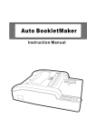
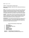
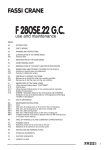
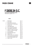
INSTRUCTION MANUAL
Span Scaffolds
!
W A R N I N G
!
Before using UpRight Scaffolds, read, understand and follow all Safety Rules, Erection Instructions and Maintenance
Rules. Keep this manual for future reference. It contains important safety information! Failure to properly erect,
dismantle and use Span Scaffolds may lead to death, injury or property damage. Scaffolds shall be erected, moved
and dismantled only by, or under the supervision and direction of, a competent person.
SAFETY RULES
!
D A N G E R
!
ELECTROCUTION HAZARD. This is a metal scaffold and its components can conduct electricity. DO NOT use near
energized electrical circuits. Serious injury or death will result if contact is made.
!
W A R N I N G
!
NEVER use any UpRight Scaffold or scaffold component that is damaged.
NEVER use any UpRight Scaffold that is improperly erected. (See “Inspection and Maintenance” on page 2).
NEVER mix scaffold components from other manufacturers with UpRight Scaffold components. Component dimensions
differ from one manufacturer to another and using components from more than one manufacturer in a single scaffold
could be hazardous.
ALWAYS be sure the scaffold is level at all times. When a leg is adjusted, be sure the locking collar is completely pushed
over the expanding nut and below the safety locks (See Figure 1, page 3).
NEVER make leg adjustments with anyone on a platform.
ALWAYS lock all four caster brakes before climbing the scaffold (see Figure 1, page 3).
ALWAYS make sure all locking hooks are firmly in position and latches are properly engaged. Never force locking hooks.
ALWAYS ensure that latches of all locking hinges on folding braces are locked (see Figure 2, page 3).
ALWAYS make sure interlock clips are properly inserted when extension end frames are used (see Figure 3, page 3),
NEVER use damaged interlock clips.
ALWAYS use at least two diagonal braces and one horizontal brace properly installed on each weight-bearing section of
Single-Width Span Scaffold. Double Width Span Scaffolds require double bracing.
NEVER install a horizontal brace of a span scaffold at the same level as the intersection of diagonal braces.
ALWAYS use four OUTRIGGERS if platform height will exceed three (3) times any minimum base dimension (see
Figure 4, page 3). Height must not exceed three (3) times the minimum base dimension.
ALWAYS install GUARDRAILS on single-width scaffolds and on double-width scaffolds. Check State and Local Codes
and Regulations for additional requirements.
ALWAYS install TOEBOARDS when platform height is 10ft (3M). Check State and Local Codes and Regulations for
additional requirements.
NEVER increase platform height with the adjustable legs. Use leg adjustment for leveling the scaffold.
NEVER stand on guardrails or use guardrail components to gain extra height.
NEVER place ladders chairs, boxes or any other objects on a scaffold platform to gain additional height. When additional
height is required, add more scaffold sections.
NEVER lean a ladder against a scaffold.
NEVER climb or stand on diagonal or horizontal braces.
NEVER move a scaffold when any person or materials are on the platform (See OSHA 1910.28 [A5]).
NEVER try to pull yourself or the scaffold from one place to another while on the platform. ALWAYS climb down from
the platform and reposition the scaffold.
P/N 001225-001 Rev A
Safety Rules
!
C A U T I O N
continued
!
ALWAYS ensure the work area is free of hazards such as debris and openings or holes in the surface where the
scaffold will be used. Use only a firm level surface capable of supporting the scaffold and its load.
NEVER use a scaffold without first inspecting it. Prior to use, every user of an UpRight Scaffold must thoroughly inspect
the scaffold prior to use. All required components must function properly and be properly attached as part of a properly
erected scaffold. Any incomplete part, missing label, missing part or part that does not fit properly must be replaced
prior to use of the scaffold.
NEVER use a hammer or other object to strike a component while attempting to erect, disassemble or adjust a scaffold.
The components of a properly configured UpRight Scaffold should not require the application of force during the
erection or disassembly process.
Handle all scaffold parts carefully. Do not throw or drop onto hard surfaces or allow heavy objects to fall onto the
scaffold or scaffold components.
NEVER exceed the maximum distributed platform capacity of 500 lbs (227 Kg). Maximum distributed load is 25 lbs/ft2
(122 Kg/m2) on any platform and 3000 lbs (1361 Kg) total on any base section. When adjustable legs are extended the
maximum capacity is 1,600 lbs (726 Kg).
NEVER allow loose objects to accumulate on the platform during use. Always keep the platform free of all tripping
hazards. Make sure the scaffold is free from slippery or hazardous materials such as paint or mud.
NEVER leave the scaffold unattended.
ALWAYS contact UpRight for instructions if you any questions (see BackCover). NEVER TAKE CHANCES.
I NSPECTION AND M AINTENANCE
Following Use, inspect all scaffold components before storage. All damaged or worn parts
and labels and parts not working properly must be repaired or replaced. Parts which cannot be restored to properly usable condition must be discarded.
SCAFFOLD MAINTENANCE
• All parts of UpRight Scaffolds should fit together easily and work properly. To ensure
proper function, keep all scaffold components clean. All parts should be clean and
free of any foreign build up. Use soap and water. Do not use caustic cleaner.
• The legs and sockets of scaffold end frames, where sections join each other should fit
together properly, without interference. Legs and sockets must be kept clean. Lubricate end frame legs and sockets and spring pins with light machine oil as necessary.
• The inside surface of Brace Hooks and Spring Loaded Pins should fasten in place
without forcing or binding. Keep the inside surface of Brace Hooks clean.
• Locking Hinge mechanisms should lock and unlock properly. Keep Locking Hinge
mechanisms lubricated.
• Adjustable legs must slide freely inside the base frame vertical tubes. Remove any
dirt or paint from the threads of the Adjustable Legs. Brush lightly if cleaning is necessary.
• Casters must be checked for worn or damaged wheels and missing or damaged snap
rings. Wheels should spin freely and bearing races should turn freely and smoothly.
Keep casters cleaned and lubricated. Axles, bearing races and stems must be lubricated with light machine oil. Damaged casters must be discarded.
Platforms must be checked for loose or missing components, holes or thin spots where
boards may be worn. Worn or damaged boards must be replaced.
Page 2
Instruction Manual | Span Scaffolds | 001225-001 Rev A
Adjust Legs and Lock Casters
A DJUST L EGS AND L OCK C ASTERS
Figure 1: Adjusting Legs and Casters
THREADED
NUT
OPENS
TWIST
AND RAISE
COLLAR
PAST
SAFETY
LOCKS
THREADED
LEG
SLIDES INTO
POSITION
THREADED
NUT
CLOSES
LOWER
LOCKING
COLLAR
PAST
SAFETY
LOCKS
LEG UNLOCKED
PULL
LEVER
UP
THREADED
LEG
LOCKS INTO
POSITION
LEG LOCKED
BRAKE IS
CLEAR AND
WHEEL
IS FREE
TO ROLL
PUSH
LEVER
DOWN
WHEEL IS
OFF-CENTER
AND FREE
TO SWIVEL
CASTER UNLOCKED
BRAKE IS
SET
WHEEL
WILL NOT
SWIVEL
OR ROLL
WHEEL IS
ON-CENTER
CASTER LOCKED
HOW TO ADJUST LEGS
HOW TO LOCK AND UNLOCK CASTERS
Before climbing any scaffold, make sure it is level and always check
to see that all four (4) leg adjustment collars have been pushed
all the way down past the safety locks. Never use a scaffold
unless the leg adjustment mechanism is in perfect working
order.
Before climbing any scaffold, always lock all four (4) caster
brakes. Never roll the scaffold when anyone is on it. Pushing
the single lever down sets the caster brake and moves the
wheel to dead center position for maximum scaffold rigidity.
L OCKING H INGES AND I NTERLOCK C LIPS
Figure 2: Locking Hinges
Make sure spring-actuated
latches have moved into full
locking position before using
the scaffold. Do not use the
scaffold if any of the latches
are not working properly.
Figure 3: Interlock Clips
Make sure pin on interlock
clips is seated in the locking
hole.
O UTRIGGERS
Figure 4: Outriggers
1. Always use outriggers if platform height is more than three (3) times
any minimum base dimension.
2. For single wide scaffold, outriggers are required for platform heights
above the base section (6’ 6”).
3. For double wide scaffolds, outriggers are required for platform
heights above 13’ 6”.
001225-001 Rev A | Span Scaffolds | Instruction Manual
Page 3
Scaffold Components
S CAFFOLD C OMPONENTS
GUARDRAIL
INTERLOCK CLIPS
Guardrail Frame
Part No. 470
Interlock Clip
Part No. 167
Guardrail Frame
Part No. 270
Horizontal Brace
6ft: (L–75-9/32") Part No. 223
8ft: (L–98-5/16") Part No. 105
10ft:1 (L–120") Part No. 221
Long Pin
Interlock Clip
Part No. 467
Diagonal Brace
6ft: (L–82-1/32") Part No. 364
8ft: (L–103-9/16") Part No. 365
10ft: (L–124-11/32") Part No. 210
Wind-Lock Clip
Part No. 198
HEIGHT EXTENSIONS
OUTRIGGERS
4ft Extension
End Frame
Part No. 466
4ft Extension
End Frame
Part No. 166
5ft-6in Extension
End Frame
Part No. 495
Adjustable
Outrigger
Part No. 430
5ft-6in
Extension
End Frame
Part No. 195
6ft-9in Extension
End Frame
Part No. 990
6ft-9in
Extension
End Frame
Part No. 90
Large
Adjustable
Outrigger
Part No. 1490
TOEBOARDS
Double Width (Wood)
6ft: Part No. 9616
8ft: Part No. 9618
10ft: Part No. 9620
Double Width (Aluminum)
6ft: Part No. 1316
8ft: Part No. 1318
10ft: Part No. 1320
Single Width (Wood)
6ft: Part No. 9606
8ft: Part No. 9608
10ft: Part No. 9610
Single Width (Aluminum)
6ft: Part No. 1306
8ft: Part No. 1308
10ft: Part No. 1310
Casters & Base Plates
Leg Lock Assembly
Part No. 125 & 127
PLATFORMS
Double Width
2 Required
PLATFORM ASSEMBLY
6ft: (L–75-9/32") Part No. 93-01
8ft: (L–98-9/32") Part No. 94-01
10ft: (L–120") Part No. 95-01
Adjustable Leg
Standard
Part No. 517
(L−20")
Adjustable Leg
VX Instant
Part No. 206
(L−33")
Single Width
1 Required
STANDARD BASE
6ft-6in Double Base
End Frame
Part No. 409
5in. Caster
Part No. 5061
8in. Caster
Part No. 9600
6ft-6in Single Base
End Frame
Part No. 209
HIGH CLEARANCE SPAN
5ft-6in Double Base
End Frame
Part No. 45-03
4ft Double Base
End Frame
Part No. 45-04
Swivel Base Plate
Part No. 325
5ft-6in
Single Base
End Frame
Part No. 45-01
4ft Single Base
End Frame
Part No. 45-02
HIGH CLEARANCE PLATFORM ASSEMBLY
6ft: (L–75-9/32") Part No. 40456
8ft: (L–98-5/16") Part No. 40408
10ft: (L–120") Part No. 41010
V-X BASE
V-X Double Width
Folding Structure
6ft: Part No. 1061
8ft: Part No. 1081
Lower End Frame
Single Width
(W–26-21/32")
Part No. 209
Double Width
(W–50-25/32")
Part No. 409
V-X Single Width
Folding Structure
6ft: Part No. 920
8ft: Part No. 930
DOUBLE
Page 4
(H–78" up to 90")
SINGLE
Instruction Manual | Span Scaffolds | 001225-001 Rev A
Erecting Instructions - Single Width
E RECTING I NSTRUCTIONS - S INGLE W IDTH
V-X I N S T A N T S P A N S I N G L E W I D T H S C A F F O L D - S T E P 1
1. Unlock folding base unit
2. Open Outwards
3. Lock Hinging Braces (see
“Locking Hinges” on page 3).
4. Install platform at desired
height.
STANDARD SPAN SINGLE WIDTH SCAFFOLD - STEP 1
1. Snap short brace (horizontal) onto vertical
tube of lower end frame. This supports the
frame during installation of the other braces.
2. Snap long braces (diagonal) in desired
position. Horizontal brace must be above or
below intersection of diagonal braces.
3. Install platform. Move horizontal brace to top
rung.
SINGLE WIDTH SCAFFOLD - STEP 2
1. Lock all casters. Adjust legs to level platform.
Insert extension frames. Interlock all frames
by moving interlock clips from parking holes
up to locking holes (see page 3).
2. Snap diagonal braces in place.
001225-001 Rev A | Span Scaffolds | Instruction Manual
3. Before moving platform higher than 7 ft.
(2,1m), tie the scaffold into the building or
install outrigger on each corner. Make sure
each outrigger is wedged against solid
pavement and that all couplers are securely
fastened.
Page 5
Erecting Instructions - Double Width
E RECTING I NSTRUCTIONS - D OUBLE W IDTH
V-X I N S T A N T S P A N D O U B L E W I D T H S C A F F O L D - S T E P 1
1. Roll the compact, 9.5in. (24cm)
thick package to the place to be
used.
2. Release the locking hook which
holds the unit together.
3. Roll end frames apart. Lock
hinging braces (see page 5)
4. Install platforms
STANDARD SPAN DOUBLE WIDTH SCAFFOLD - STEP 1
1. Snap short brace (horizontal)
onto vertical tube of lower end
frame.
2. Snap horizontal braces onto
vertical tubes of both lower end
frames. These support the
frames during installation of
other braces.
3. Snap four(4) diagonal braces
between lower end frames. Be
sure horizontal braces are
installed above or below the
intersection of the diagonals.
4. Install platforms at desired
height.
DOUBLE WIDTH SCAFFOLD - STEP 2
1. Lock all casters. Adjust legs to level platform.
Insert extension frames; be sure each set of
extensions includes four (4) diagonal braces
and two (2) horizontal braces. Interlock all
frames by moving interlock clips from parking
holes up to locking holes (see page 3)
Page 6
2. Install platforms. Add extension frames,
diagonal braces and guardrail frames and
braces.
3. Install guardrail frames and toeboards.
See page 7 for maximum heights.
Instruction Manual | Span Scaffolds | 001225-001 Rev A
Height to Base Ratio Tables
H EIGHT TO B ASE R ATIO TABLES
SINGLE WIDTH SPAN
430
ADJUSTABLE
OUTRIGGER
44”
DOUBLE WIDTH SPAN
SCAFFOLD
LENGTH
WIDTH
MAXIMUM SCAFFOLD
PLATFORM
WIDTH &
HEIGHT
LENGTH
LENGTH
WIDTH
MAXIMUM
WIDTH &
LENGTH
WITH
STABILIZERS
WITH
STABILIZERS
WITH
STABILIZERS
WITH
STABILIZERS
PLATFORM
HEIGHT
29” X 10”
10’ – 0”
9’ – 7”
28’ – 6”
4’ 6” X 10’
11’ – 5”
11’ – 5”
34’ – 0”
29” X 8”
9’ – 5”
9’ – 5”
28’ – 6”
4’ 6” X 8’
11’ – 0”
11’ – 0”
34’ – 6”
29” X 6”
9’ – 0”
9’ – 0”
27’ – 0”
4’ 6” X 6’
10’ – 4”
10’ – 4”
31’ – 0”
29” X 10”
12’ – 4”
12’ – 4”
36’ – 6”
4’ 6” X 10’
13’ – 10”
13’ – 10”
40’ – 6”
29” X 8”
11’ – 11”
11’ – 11”
35’ – 0”
4’ 6” X 8’
12’ – 10”
12’ – 10”
38’ – 6”
29” X 6”
11’ – 4”
11’ – 4”
34’ – 0”
4’ 6” X 6’
12’ – 6”
12’ – 6”
37’ – 6”
1490
EXTRA
LENGTH
OUTRIGGER
62”
These tables are calculated on the maximum platform height allowable, based on three (3) times the minimum base
dimension with stabilizers attached.
UpRight SCAFFOLDS HAVE BEEN DESIGNED AND TESTED TO MEET OR EXCEED APPLICABLE OSHA AND
ANSI REQUIREMENTS
001225-001 Rev A | Span Scaffolds | Instruction Manual
Page 7
USA
CONTACT:
UpRight
2686 S. Maple Avenue
Fresno, CA, 93725
Telephone: (559) 443 6600
Toll Free: (866) 843-3350
Fax:
(559) 268 1756
Email:
[email protected]
www.uidistribution.com
P/N 001225-001 Rev A
07-06