1
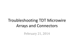
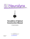
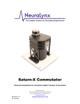
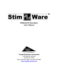
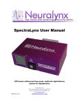
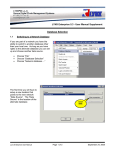
Digital Lynx SX Upgrade
User’s Manual
Upgrade for compatibility with the HS-xx-mux Headstage
© Neuralynx, Inc.
105 Commercial Drive, Bozeman, MT 59715
Phone 406.585.4542 • Fax 866.585.1743
Neuralynx.com
Revision 1.0
3/14/2014
[email protected]
Table of Contents
1 Document Overview ..................................................................................................... 2 2 HS-xx-mux Overview ................................................................................................... 3 2.1 Important Note ....................................................................................................... 3 3 What's included with the Digital Lynx SX multiplexing headstage Upgrade? ............ 4 3.1 Multiplexing Headstage Adapter ........................................................................... 4 3.2 Additional Testing Items........................................................................................ 4 3.2.1 SM-32/64 ........................................................................................................ 5 3.2.2 HS-36 Impedance Plug ................................................................................... 5 3.3 Electrostatic Sensitive Equipment ......................................................................... 5 4 Installing the Upgrade Hardware .................................................................................. 6 4.1 Special Tools Required .......................................................................................... 6 4.2 Protect Against Electrostatic Discharge................................................................. 6 4.3 Disconnect the Digital Lynx SX Motherboard ...................................................... 7 4.4 Install the Multiplexing Headstage Adapter .......................................................... 9 4.5 Reconnect the Digital Lynx SX Motherboard ..................................................... 11 5 Installing the Digital Lynx SX Firmware Update ....................................................... 12 6 Glossary ...................................................................................................................... 13 List of Figures and Tables
Figure 3-1 Digital Headstage Adapter ................................................................................ 4 Figure 3-2 SM-64................................................................................................................ 5 Figure 3-3 HS-36 Impedance Plug ..................................................................................... 5 Figure 4-1 Connect the Cord to the Digital Lynx SX ......................................................... 6 Figure 4-2 Connect the Cord to the Static Strap ................................................................. 7 Figure 4-3 Wear the Static Strap ......................................................................................... 7 Figure 4-4 Loosen Two Screws .......................................................................................... 8 Figure 4-5 Eject the Digital Lynx SX Motherboard ........................................................... 8 Figure 4-6 Disconnection Points......................................................................................... 9 Figure 4-7 Remove Faceplate Screws................................................................................. 9 Figure 4-8 Multiplexing Headstage Adapter(Mezz) Connection ..................................... 10 Figure 4-9 40 Pin Ribbon Cable Connection .................................................................... 10 Figure 4-10 40 Pin Ribbon Cable Connection .................................................................. 11 Figure 4-11 Connection Points ......................................................................................... 11 Figure 4-12 Digital Lynx SX ............................................................................................ 12 1 Document Overview
This document explains how to upgrade your Digital Lynx SX for compatibility with the
multiplexing headstage. The additional hardware and software requirements are outlined
and there is a glossary at the end of the document.
Revision 1.0
3/14/2014
Digital Lynx SX Upgrade User’s Manual
Page 2
2 HS-xx-mux Overview
The multiplexing headstage is a multiplexing headstage that records from up to 64
individual electrodes. The physiological signals are digitized at the headstage, meaning
the required number of cable conductors is greatly reduced.
Features:
• Versions include HS-32-mux and the HS-64-mux.
• ±5mV Input Range.
• >80dB Common Mode Rejection Ratio(CMRR) at 60Hz.
• <2.5µVRMS Noise (0.1Hz to 9kHz).
• Interfaces directly with Digital Lynx SX.
• 25 Conductor Cable transfers up to 64 channels to Digital Lynx SX.
• Up to 128 Digital Channels per Digital Lynx SX.
• Compatible with Neuralynx EIBs.
2.1 Important Note
The multiplexing headstage must be connected to the Digital Lynx SX before the system
is powered ON. Otherwise the system won’t recognize that a multiplexing headstage is
present.
Revision 1.0
3/14/2014
Digital Lynx SX Upgrade User’s Manual
Page 3
3 What's included with the Digital Lynx SX multiplexing
headstage Upgrade?
3.1 Multiplexing Headstage Adapter
The Multiplexing Headstage Adapter is the interface between the multiplexing headstage
and the Digital Lynx SX. It allows for up to 2 HS-64-mux (128 Digital Channels) to be
connected to the Digital Lynx SX. The Multiplexing Headstage Adapter is provided with
a new Digital Lynx SX Motherboard Faceplate.
Figure 3-1 Digital Headstage Adapter
3.2 Additional Testing Items
Additionally, a Signal Mouse (SM-32/64) and an Impedance Plug (HS-36 Impedance
Plug), can be purchased as separate items for testing the signal through the multiplexing
headstage and the Digital Lynx SX.
Revision 1.0
3/14/2014
Digital Lynx SX Upgrade User’s Manual
Page 4
3.2.1 SM-32/64
•
•
Interface for driving test
signals into the multiplexing
headstage.
Switches control Bank 1, Bank
2, Bank 3, Bank 4, and the
Reference.
Figure 3-2 SM-64
3.2.2 HS-36 Impedance Plug
•
Test plug with different
resistance values on each bank
of eight channels.
Figure 3-3 HS-36 Impedance Plug
3.3 Electrostatic Sensitive Equipment
All Neuralynx Equipment is Electrostatic Sensitive and should be handled with
appropriate measures. Always wear a static strap and use all appropriate ESD measures
when handling any electronics. Please contact Neuralynx for detailed information if you
have questions.
Revision 1.0
3/14/2014
Digital Lynx SX Upgrade User’s Manual
Page 5
4 Installing the Upgrade Hardware
4.1 Special Tools Required
1. Phillips-head Screwdriver.
4.2 Protect Against Electrostatic Discharge
While installing the Digital Headstage Adapter, it is extremely important to protect the
Digital Lynx SX from electrostatic discharge. For this reason a static wrist strap is
provided with the Digital Headstage Adapter. Properly ground yourself before handling
any electronics using the following instructions.
1. Open the package containing the Static Wrist Strap, Cord, and Alligator Clip.
2. Connect the banana plug end of the cord to the socket on the back of the Digital
Lynx SX labeled Gnd. Refer to the figure below.
Figure 4-1 Connect the Cord to the Digital Lynx SX
3. Guide the Cord toward the front of the Digital Lynx SX.
4. Attach the other end of the Cord to the snap on the Static Wrist Strap. Refer to the
figure below.
Revision 1.0
3/14/2014
Digital Lynx SX Upgrade User’s Manual
Page 6
Figure 4-2 Connect the Cord to the Static Strap
5. Wear the Static Wrist Strap on either wrist. Refer to the figure below.
Figure 4-3 Wear the Static Strap
4.3 Disconnect the Digital Lynx SX Motherboard
1. Disconnect any cables connected to the front of the Digital Lynx SX.
2. With a Phillips-head screwdriver loosen the two screws securing the Digital Lynx
SX Motherboard to the Digital Lynx SX. These screws are outlined in the figure
below.
Revision 1.0
3/14/2014
Digital Lynx SX Upgrade User’s Manual
Page 7
Figure 4-4 Loosen Two Screws
3. Press the white release button on the top and bottom latch of the Digital Lynx SX
Motherboard. Push the top latch up and the bottom latch down to eject the Digital
Lynx SX Motherboard from the Digital Lynx SX.
Figure 4-5 Eject the Digital Lynx SX Motherboard
4. Slowly slide the Digital Lynx SX Motherboard about halfway out of the Digital
Lynx SX. Up to three connectors need to be disconnected before completely
removing the Digital Lynx SX Motherboard.
5. Remove the optical fiber cable from location #1. Refer to the figure below.
6. Remove the optical fiber cable from location #2. Refer to the figure below.
7. Remove the 20 pin ribbon cable from location #3. Refer to the figure below.
a. NOTE: Some models of the Digital Lynx SX do not have this connection.
Revision 1.0
3/14/2014
Digital Lynx SX Upgrade User’s Manual
Page 8
Figure 4-6 Disconnection Points
8. Completely remove the Digital Lynx SX Motherboard from the Digital Lynx SX.
4.4 Install the Multiplexing Headstage Adapter
1. Disconnect the ribbon cable attached to the connector labeled J1 on the Digital
Lynx SX Motherboard.
a. NOTE: Some models of the Digital Lynx SX do not have this connection.
2. Place the Digital Lynx SX Motherboard on a flat solid surface with the LCD
Screen down.
3. With a Phillips-head screwdriver loosen and remove the screws securing the
Faceplate to the Digital Lynx SX Motherboard. Hold onto these screws, they will
be used to secure the new Faceplate to the Digital Lynx SX Motherboard.
Figure 4-7 Remove Faceplate Screws
Revision 1.0
3/14/2014
Digital Lynx SX Upgrade User’s Manual
Page 9
4. Remove the Faceplate from the Digital Lynx SX Motherboard. This Faceplate is
yours to keep.
a. Note: This is a tight fit, care should be taken not to stress the Digital Lynx
SX Motherboard while doing this.
5. Slide the new Faceplate, with Multiplexing Headstage Adapter provided attached,
onto the front of the Digital Lynx SX Motherboard.
a. Note: This is a tight fit, care should be taken not to stress the Digital Lynx
SX Motherboard while doing this.
6. Secure the Faceplate to the Digital Lynx SX Motherboard with the original screws.
7. Connect the part of the Multiplexing Headstage Adapter labeled Digital
Headstage Adapter(Mezz) to the connector labeled J2 on the Digital Lynx SX
Motherboard. Refer to the figure below.
Figure 4-8 Multiplexing Headstage Adapter(Mezz) Connection
8. Connect the 40 pin ribbon cable attached to the Multiplexing Headstage Adapter
to the connector labeled J1 on the Digital Lynx SX Motherboard. Refer to the
figure below.
Figure 4-9 40 Pin Ribbon Cable Connection
Revision 1.0
3/14/2014
Digital Lynx SX Upgrade User’s Manual
Page 10
9. Connect both 2 pin sockets to the TTL Driver headers on Digital Lynx SX
Motherboard. The label on each socket needs to face towards the Faceplate. Refer
to the figure below.
a. NOTE: Some models of the Digital Lynx SX do not have this connection.
Figure 4-10 40 Pin Ribbon Cable Connection
4.5 Reconnect the Digital Lynx SX Motherboard
1. Align the Digital Lynx SX Motherboard on the green card guides and slowly slide
it about halfway into of the Digital Lynx SX. Up to three connectors need to be
reconnected before completely inserting the Digital Lynx SX Motherboard.
2. Reconnect the optical fiber cable labeled 1 to location #1.
3. Reconnect the optical fiber cable labeled 2 to location #2.
4. Reconnect the 20 pin ribbon cable to location #3.
a. NOTE: Some models of the Digital Lynx SX do not have this connection.
Figure 4-11 Connection Points
5. Continue sliding the Digital Lynx SX Motherboard into the Digital Lynx SX until
it makes contact with the backplane in the Digital Lynx SX.
Revision 1.0
3/14/2014
Digital Lynx SX Upgrade User’s Manual
Page 11
6. Gently but firmly push on the left side of the Digital Lynx SX Motherboard
Faceplate to engage the connectors.
a. Note: Do not try to force the Digital Lynx SX Motherboard all the way
into the Digital Lynx SX.
7. Squeeze the top latch down and the bottom latch up to fully insert the Digital
Lynx SX Motherboard into the Digital Lynx SX. Refer to the figure below
Figure 4-12 Digital Lynx SX
5 Installing the Digital Lynx SX Firmware Update
Digital Lynx SX Firmware Update Version 1.30 or later is required to use the
multiplexing headstage. The Firmware package can be downloaded from the Neuralynx
Website:
Neuralynx.com > Software > Drivers and Firmware > Digital Lynx SX Firmware
Update Version 1.30
Instructions for installing the Firmware Update are contained in the download package.
Revision 1.0
3/14/2014
Digital Lynx SX Upgrade User’s Manual
Page 12
6 Glossary
CSC – Neuralynx acronym for Continuously Sampled Channel.
EIB – Neuralynx acronym for Electrode Interface Board.
Multiplexing Headstage (mux)– Headstage that digitized the physiological signals at the
headstage. XX denotes the number of channels (ie. HS-32-mux digitizes 32 physiological
signals).
Revision 1.0
3/14/2014
Digital Lynx SX Upgrade User’s Manual
Page 13