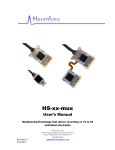
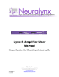
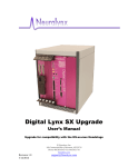
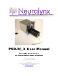
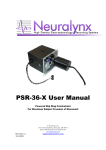
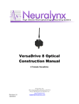
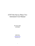
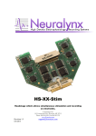
1
The Complete Solution for Electrophysiology Research
Saturn-X Commutator
Powered Commutator for maximum subject freedom of movement
© Neuralynx, Inc.
105 Commercial Drive, Bozeman, MT 59715
Phone 406.585.4542 • Fax 866.585.1743
www.Neuralynx.com
Revision 1.0
02/19/2014
[email protected]
Table of Contents
1 2 3 Document Overview ................................................................................................... 4 Saturn-X Commutator Overview ................................................................................ 4 What's Included with the Saturn-X Commutator? ...................................................... 5 3.1 Saturn-X Commutator .......................................................................................... 5 3.2 Saturn-X Power Supply........................................................................................ 5 3.3 Additional Items Sold Separately......................................................................... 5 3.3.1 TETH-XTN-MM .......................................................................................... 5 3.3.2 Tether Interconnect ....................................................................................... 6 3.3.3 FORJ Mount ................................................................................................. 6 3.3.4 ADPT-HS-36-PSR-36 .................................................................................. 6 3.3.5 ADPT-HS-18-DUAL-PSR ........................................................................... 7 3.3.6 ADPT-HS-27-PSR-36 .................................................................................. 7 3.3.7 Remote .......................................................................................................... 7 3.4 Electrostatic Sensitive Equipment........................................................................ 7 4 Quick Start .................................................................................................................. 8 4.1 Saturn-X Commutator Setup ................................................................................ 8 4.2 Start Cheetah ........................................................................................................ 9 4.3 Drive Signal into the Saturn-X Commutator........................................................ 9 5 Computer Control ..................................................................................................... 13 5.1 Installing the USB Drivers ................................................................................. 13 5.2 Setting Up the Terminal Window ...................................................................... 13 5.3 Terminal Window Options ................................................................................. 15 5.3.1 Set Min Speed ............................................................................................. 15 5.3.2 Set Max Speed ............................................................................................ 15 5.3.3 Set Remote Speed ....................................................................................... 15 5.3.4 Set Acceleration Speed ............................................................................... 15 5.3.5 Speed Ramp ................................................................................................ 15 5.3.6 Set Stop Angle ............................................................................................ 15 5.3.7 Set Start Angle ............................................................................................ 15 5.3.8 Calibrate Home Position ............................................................................. 16 5.3.9 LED Speed indicator ................................................................................... 16 5.3.10 Reset Factory Defaults ................................................................................ 16 5.3.11 Reprint Menu .............................................................................................. 16 6 Mounting ................................................................................................................... 17 7 Optical and Fluid Integration .................................................................................... 18 8 Glossary .................................................................................................................... 19 9 Appendix ................................................................................................................... 20 9.1 Saturn-X Commutator LED Indicator Descriptions........................................... 20 9.2 Saturn-X Commutator Dimensions .................................................................... 21 Revision 1.0
02/19/2014
Saturn-X Commutator
Page 2
List of Figures and Tables
Figure 3-1 Saturn-X Commutator ....................................................................................... 5 Figure 3-2 Saturn-X Power Supply..................................................................................... 5 Figure 3-3 TETH-XTN-MM............................................................................................... 5 Figure 3-4 Tether Interconnect ........................................................................................... 6 Figure 3-5 FORJ Mount ...................................................................................................... 6 Figure 3-6 ADPT-HS-36-PSR-36 ....................................................................................... 6 Figure 3-7 ADPT-HS-18-DUAL-PSR................................................................................ 7 Figure 3-8 ADPT-HS-27-PSR-36 ....................................................................................... 7 Figure 3-9 Remote .............................................................................................................. 7 Figure 4-1 Hardware Connections ...................................................................................... 8 Figure 4-2 Bank 1, 2, 3 and 4 Switches Up. Reference Switch Down. .............................. 9 Figure 4-3 Bank 2, 3 and 4 Switches Up. Bank 1 and Reference Switches Down........... 10 Figure 4-4 Bank 3 and 4 Switches Up. Bank 1, 2 and Reference Switches Down........... 10 Figure 4-5 Bank 4 Switches Up. Bank 1, 2, 3 and Reference Switches Down. ............... 11 Figure 4-6 All Switches Down (1000µV)......................................................................... 11 Figure 4-7 All Switches Down (25µV)............................................................................. 12 Figure 4-8 All Switches Up (25µV). ................................................................................ 12 Figure 5-1 Driver Installation Window............................................................................. 13 Figure 5-2 Found New Hardware ..................................................................................... 13 Figure 5-3 COM Port Number .......................................................................................... 14 Figure 5-4 Terminal Window Setup ................................................................................. 14 Figure 5-5 Terminal Window ........................................................................................... 15 Figure 7-1 FORJ Integration ............................................................................................. 18 Figure 9-1 LED Status Indicators ..................................................................................... 20 Figure 9-2 Saturn-X Commutator Dimensions – Front View .......................................... 21 Figure 9-3 Saturn-X Commutator Dimensions – Side View ............................................ 22 Revision 1.0
02/19/2014
Saturn-X Commutator
Page 3
1 Document Overview
This document describes the specifications and features of the Saturn-X Commutator. It
also explains how to setup your Saturn-X, test it, and use it during normal operation.
There is a glossary at the end of the document.
2 Saturn-X Commutator Overview
This Saturn-X Commutator is a powered slip ring commutator that allows tethers
connected to the research subject to rotate independently of the data acquisition system.
Features:
• Power Commutator
• High Sensitivity
• Up to 160 channels
• Adds Minimal Addition Noise
• User Programmable
• Optional Remote Control
Revision 1.0
02/19/2014
Saturn-X Commutator
Page 4
3 What's Included with the Saturn-X Commutator?
There are six different channel counts available the; Saturn Mini, Saturn-1, Saturn-2,
Saturn-3, Saturn-4, and Saturn-5.
3.1 Saturn-X Commutator
•
•
•
•
•
1 to 5 Channel Modules
32 AD Channels, 4 References,
2 Stimulus Pairs per Channel
Module, except for Saturn
Mini, which contains 16 AD
Channels, 2 References, 2
Stimulus Pairs.
Compatible with Neuralynx
Flex Tether Adapters.
9.5 inches to 13.5 inches tall.
3.4kg to 6.5kg.
Figure 3-1 Saturn-X Commutator
3.2 Saturn-X Power Supply
•
•
AC/DC Power Supply.
24V, 1.67A.
Figure 3-2 Saturn-X Power Supply
3.3 Additional Items Sold Separately
3.3.1 TETH-XTN-MM
•
•
Extension Cable that connects
the Saturn-X Commutator to
the Data Acquisition System.
Standard lengths include 1
meter, 2 meters, 5 meters, and
8 meters.
Figure 3-3 TETH-XTN-MM
Revision 1.0
02/19/2014
Saturn-X Commutator
Page 5
3.3.2 Tether Interconnect
•
Allows multiple TETH-XTNMMs to connect together.
Figure 3-4 Tether Interconnect
3.3.3 FORJ Mount
•
•
Hardware for mounting rotary
joint to the top of the Saturn-X
Commutator.
17mm and 29mm Diameter
Mounts available.
Figure 3-5 FORJ Mount
3.3.4 ADPT-HS-36-PSR-36
•
Allows a single HS-36 to
connect to the Saturn-X
Commutator.
Figure 3-6 ADPT-HS-36-PSR-36
Revision 1.0
02/19/2014
Saturn-X Commutator
Page 6
3.3.5 ADPT-HS-18-DUAL-PSR
•
Allows two HS-16/18s to
connect to the Saturn-X
Commutator.
Figure 3-7 ADPT-HS-18-DUAL-PSR
3.3.6 ADPT-HS-27-PSR-36
•
Allows a single HS-27 or HS16/18 to connect to the SaturnX Commutator.
Figure 3-8 ADPT-HS-27-PSR-36
3.3.7 Remote
•
Allows manual control of the
Saturn-X Commutator.
Figure 3-9 Remote
3.4 Electrostatic Sensitive Equipment
All Neuralynx Equipment is Electrostatic Sensitive and should be handled with
appropriate measures. Always wear a static strap and use all appropriate ESD measures
when handling any electronics. Please contact Neuralynx for detailed information if you
have questions.
Revision 1.0
02/19/2014
Saturn-X Commutator
Page 7
4 Quick Start
The following instructions are provided to quickly setup and test your Saturn-X
Commutator setup. Note, the Saturn-X Commutator should be allowed to warm up to
room temperature before performing the steps in the following section.
4.1 Saturn-X Commutator Setup
The Saturn-X Commutator connections are illustrated and described below.
Figure 4-1 Hardware Connections
Connections:
1. Mount the Saturn-X Commutator.
2. Connect the 24V Saturn-X Power Supply to the connector labeled Power on the
Saturn-X Commutator.
3. Connect one end of the TETH-XNT-MM Extension Cable to Data Acquisition
System.
4. Connect the other end of the TETH-XNT-MM Extension Cable to the connector
labeled Module 1 on the Saturn-X Commutator.
5. Connect the Headstage to the Flex Tether on the Saturn-X Commutator.
6. Connect the Headstage to the Signal Mouse.
7. Connect the Minirator, or other signal source, to the Signal Mouse using a BNC
Cable.
Revision 1.0
Saturn-X Commutator
02/19/2014
Page 8
8. Turn the Bank 1, 2, 3, and 4 switches on the Signal Mouse to the Signal Position
(Up). Turn the Reference switch on the Signal Mouse to the Ground Position
(Down).
9. Set the Minirator, or other signal source, to output a 1VPP Sine Wave at 100 Hz.
The Signal Mouse will reduce this signal to approximately 1mVPP.
10. Power the Saturn-X Commutator ON.
11. Power the Digital Lynx SX ON.
4.2 Start Cheetah
Power On the Digital Lynx SX and wait for boot cycle to complete. On the Desktop
select the Run Cheetah shortcut to open the Cheetah Welcome Screen. Boot Cheetah with
a your preferred configuration file for your new setup. In this example 32 CSCs are used.
4.3 Drive Signal into the Saturn-X Commutator
In Cheetah, select the ACQ Button to Start Acquisition. Set the Input Range for all 32
CSCs to 1000µV and set the Reference for all 32 CSCs to Reference 1. Observe the 32
CSCs. Each should show a reduced (approximately 1mVPP) version of the Minirator
output. Refer to the figure below.
Figure 4-2 Bank 1, 2, 3 and 4 Switches Up. Reference Switch Down.
Switch the Bank 1 Switch to the Ground Position (Down). Observe the 32 CSCs. CSCs
1-8 should now be flatlined while CSCs 9-32 still show a reduced (roughly 1mVPP)
version of the Minirator output. Refer to the figure below.
Revision 1.0
02/19/2014
Saturn-X Commutator
Page 9
Figure 4-3 Bank 2, 3 and 4 Switches Up. Bank 1 and Reference Switches Down.
Switch the Bank 2 Switch to the Ground Position (Down). Observe the 32 CSCs. CSCs
1-16 should now be flatlined while CSCs 17-32 still show a reduced (roughly 1mVPP)
version of the Minirator output. Refer to the figure below.
Figure 4-4 Bank 3 and 4 Switches Up. Bank 1, 2 and Reference Switches Down.
Switch the Bank 3 Switch to the Ground Position (Down). Observe the 32 CSCs. CSCs
1-24 should now be flatlined while CSCs 25-32 still show a reduced (roughly 1mVPP)
version of the Minirator output. Refer to the figure below.
Revision 1.0
02/19/2014
Saturn-X Commutator
Page 10
Figure 4-5 Bank 4 Switches Up. Bank 1, 2, 3 and Reference Switches Down.
Switch the Bank 4 Switch to the Ground Position (Down). Observe the 32 CSCs. CSCs
1-32 should now be flatlined. Refer to the figure below.
Figure 4-6 All Switches Down (1000µV).
Set the Input Range for all 32 CSCs to 25µV. Observe the 32 CSCs. CSCs 1-32 now
show the baseline noise. Each should be less than 25µVpp and void of any repetitive
signals. Refer to the figure below.
Revision 1.0
02/19/2014
Saturn-X Commutator
Page 11
Figure 4-7 All Switches Down (25µV).
Force the Saturn-X Commutator to spin. Observe the 32 CSCs. CSCs 1-32 should still
show the baseline noise. Each should be less than 25µVpp and void of any repetitive
signals.
Switch all the Switches to the Signal Position (Up). Observe the 32 CSCs. Each should
be less than 25µVpp and void of any repetitive signals. Refer to the figure below.
Figure 4-8 All Switches Up (25µV).
Revision 1.0
02/19/2014
Saturn-X Commutator
Page 12
5 Computer Control
5.1 Installing the USB Drivers
Computer control over the Saturn-X Commutator is accomplished via a Virtual COM
Port and a USB to Serial UART IC in the device. The drivers for the Virtual COM Port
can be found at the Neuralynx website under the Software Section. By enabling this
connection, the user can access control settings for the Saturn-X Commutator. These
include Speed, Acceleration, Start Angle, Stop Angle, and Home Position.
Once the driver package has been downloaded the drivers for the Virtual COM Port can
be found in the Folder labeled USB Drivers. Install the drivers by running the
CDMXXXXX_Setup.exe file. The window in the figure below will appear.
Figure 5-1 Driver Installation Window
It may take a few minutes to install the drivers. When it is finished, make sure the
window states: "FTDI CDM Driver Installation process completed." Once the drivers
have been installed the window will close itself.
You can now attach the Saturn-X Commutator to your computer with the USB Cable.
After cycling through some Found New Hardware popups the popup shown in the
following figure will appear confirming the driver was installed properly.
Figure 5-2 Found New Hardware
5.2 Setting Up the Terminal Window
PuTTY, a free Terminal Window is also included in the driver package.
Before opening the Terminal Window the COM Port Number must first be found. Do this
by opening the Device Manager and expanding the Ports (COM and LPT) tab. Open the
Revision 1.0
02/19/2014
Saturn-X Commutator
Page 13
Device Manager by right-clicking on the My Computer Icon followed by selecting
Properties then selecting the Hardware Tab and finally clicking Device Manager. The
COM Port Number will be listed after the USB Serial Port. The COM Port Number of the
figure below is COM7.
Figure 5-3 COM Port Number
Now that the COM Port Number has been obtained, the Terminal Window can be
configured. Do this by opening the File PuTTy.exe found in the PuTTY Folder. The
window in the following figure will appear.
Figure 5-4 Terminal Window Setup
Enter the COM Port Number found earlier into the text box below Serial Line. Select
Default Settings under Saved Sessions and click Save. Click Cancel when finished. The
Terminal Window has now been configured.
Now open PuTTY.exe in the root folder. Press “99” then Enter on the Keyboard, the
Terminal Window should display the Auto Mode choices as shown in the figure below. If
the Terminal Window does match the figure below the Terminal Window has been
configured properly.
Revision 1.0
02/19/2014
Saturn-X Commutator
Page 14
Figure 5-5 Terminal Window
5.3 Terminal Window Options
5.3.1 Set Min Speed
Sets the minimum pulse rate for the Saturn-X Commutator motor.
5.3.2 Set Max Speed
Sets the maximum pulse rate for the Saturn-X Commutator motor.
5.3.3 Set Remote Speed
Sets the pulse rate for the Saturn-X Commutator motor in Manual Mode.
5.3.4 Set Acceleration Speed
When combined with Ramp Setting, sets the speed at which the Saturn-X Commutator
motor accelerates from its minimum pulse rate to its maximum pulse rate, based on the
amount of tether displacement.
5.3.5 Speed Ramp
When combined with Acceleration Setting, sets the speed at which the Saturn-X
Commutator motor accelerates from its minimum pulse rate to its maximum pulse rate,
based on the amount of tether displacement.
5.3.6 Set Stop Angle
Sets the number of displacement degrees from the home position at which the motor will
stop spinning.
5.3.7 Set Start Angle
Sets the number of displacement degrees from the home position at which the motor will
start spinning.
Revision 1.0
02/19/2014
Saturn-X Commutator
Page 15
5.3.8 Calibrate Home Position
Calibrates the home position of the Saturn-X Commutator.
5.3.9 LED Speed indicator
Enables and Disables the Status LED on the Saturn-X Commutator.
5.3.10
Reset Factory Defaults
Resets the Saturn-X Commutator to factory defaults. The Saturn-X Commutator will
most likely immediately begin spinning after selecting this option.
5.3.11
Reprint Menu
Simply reprints the Neuralynx Commutator Controller Menu.
Revision 1.0
02/19/2014
Saturn-X Commutator
Page 16
6 Mounting
The Saturn-X Commutator is designed to be mounted above an experiment location,
usually at the ceiling of the experiment room. The Saturn-X Commutator platform
should be mounted as parallel to the floor as possible. Vibration in the mounting
structure can cause the torque sensor to shift enough to cause motor rotation. If this
happens with nothing attached to provide counter torque, the motor will spin
continuously until counter torque is applied or power is removed. The chance of this
unintended rotation occurring can be reduced by using the sensitivity threshold jumpers.
Due to the difficulty of locating the Cheetah system near the ceiling, the Saturn-X
Commutator is always used with the Neuralynx tether extension, which also protects the
delicate wiring from damage in a potentially hostile ceiling environment. The Neuralynx
headstage buffers are able to drive up to 25 feet of tether extension cable with no increase
in system noise. In most cases, the use of the Saturn-X Commutator and extension
cabling should be transparent to the performance of the system. It is suggested, however,
that the power cabling for the Saturn-X Commutator be run at least half of one meter
away from the tether extension (along its entire length), in order to avoid conducting
power supply noise into the electrode signals. This is not a hard requirement but is
strongly recommended.
The flex circuit tether exiting the bottom of the Saturn-X Commutator is connected to the
headstage tether using the appropriate adapter board. The tether and headstage assembly
are usually left plugged in after mounting. The animal is disconnected and reconnected
to the hanging tether and headstage each day.
Revision 1.0
02/19/2014
Saturn-X Commutator
Page 17
7 Optical and Fluid Integration
The Saturn-X Commutator comes pre-designed for optical and fluid integration. This
mount can be purchased separate and can be added at anytime after initial installation.
The Saturn-X Commutator unit works independently of the FORJ or Fluid Rotary Joint.
The mount does not include either fluid or optical joint. These must be purchased
separately.
Figure 7-1 FORJ Integration
Revision 1.0
02/19/2014
Saturn-X Commutator
Page 18
8 Glossary
CSC – Neuralynx acronym for Continuously Sampled Channel.
EIB – Neuralynx acronym for Electrode Interface Board.
HS – Neuralynx acronym for Headstage.
Saturn-X Commutator – Powered slip ring commutator. X denotes the number of
Channel Modules (ie. Saturn-1 contains one Channel Module).
Revision 1.0
02/19/2014
Saturn-X Commutator
Page 19
9 Appendix
9.1 Saturn-X Commutator LED Indicator Descriptions
•
Saturn-X Commutator powered Off.
•
•
Saturn-X Commutator powered On.
Power Good.
•
•
•
Saturn-X Commutator powered On.
Power Good.
Motor Spinning.
•
•
•
Saturn-X Commutator powered On.
Power Good.
Device in Manual Mode
•
USB Cable connected to Saturn-X
Commutator.
•
•
Serious power problem.
Contact Neuralynx for support.
•
•
•
•
Saturn-X Commutator powered On.
Power Good.
Serious Saturn-X Commutator problem.
Contact Neuralynx for support.
Figure 9-1 LED Status Indicators
Revision 1.0
02/19/2014
Saturn-X Commutator
Page 20
9.2 Saturn-X Commutator Dimensions
Figure 9-2 Saturn-X Commutator Dimensions – Front View
Revision 1.0
02/19/2014
Saturn-X Commutator
Page 21
Figure 9-3 Saturn-X Commutator Dimensions – Side View
Revision 1.0
02/19/2014
Saturn-X Commutator
Page 22