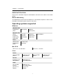
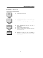
1
easyRAID S8A2 (PCIe Host Interface) 42-30000-5106 PCIe to Serial ATA II Disk Array System Version 1.1 PCIe to Serial ATA II Disk Array System easyRAID S8A2 Software Manual Preface Preface Notice Product features and specifications described in this manual are subject to change without notice. The manufacturer shall not be liable for any damage, or for the loss of information resulting from the performance or use of the information contained herein. Trademarks The names of products and logos referenced herein are trademarks and/or service marks or registered trademarks and/or service marks. Microsoft, Windows, Windows NT, Windows 2000, Windows 2003, Windows XP, Windows Vista and MS-DOS are either trademarks or registered trademarks of Microsoft Corporation. Intel and Pentium are registered trademarks of Intel Corporation. Mac, Mac OS, and Macintosh are either registered trademarks or trademarks of Apple. Other product and company names mentioned herein may be trademarks and/or service marks of their respective owners. All contents of this manual are copyrighted The information contained herein is the exclusive property and shall not be copied, transferred, photocopied, translated on paper, film, electronic media, or computerreadable form, or otherwise reproduced in any way, without the express written permission Manual version 1.1 © Copyright 2007 All rights reserved. 1 RAIDGuard X User’s Manual About this manual Thank you for choosing an RAID storage solution. This manual takes you step by step through the installation and configuration of the RAIDGuard X software. PART ONE: Introduction Chapter 1: PART TWO: Introduction provides an overview of the software and its features. Software Installation Chapter 2: Installing RAIDGuard X on Windows Chapter 3: Installing RAIDGuard X on Mac OS Chapter 4: Installing RAIDGuard X on Linux PART THREE: Basic RAID Configuration Chapter 5: RAIDGuard X Server Chapter 6: Basic Configuration using RAIDGuard X Client PART FOUR: Advanced RAID Configuration Chapter 7: PART FIVE: Advanced Configuration Appendices Appendix A: Glossary – defines relevant technical terms used in this manual. Appendix B: RAIDGuard X GUI Icons – lists the icons and their functions used in the application. Appendix C: Introduction to RAID Levels – describes all available RAID levels available from this software. Appendix D: Contact Us – lists contact details of business units around the world. Guide to conventions Important information that users should be aware of is indicated with the following icons: This icon indicates the existence of a potential hazard that could result in personal injury, damage to your equipment or loss of data if the safety instruction is not observed. This icon indicates useful tips on getting the most from your software. Important terms, commands and programs are put in Boldface font. 2 Table of Contents Table of Contents PREFACE .........................................................................................................................1 NOTICE ...........................................................................................................................1 TRADEMARKS .................................................................................................................1 ABOUT THIS MANUAL .....................................................................................................2 GUIDE TO CONVENTIONS ................................................................................................2 TABLE OF CONTENTS............................................................................................3 USING THIS SECTION .......................................................................................................5 CHAPTER 1 INTRODUCTION .........................................................................................6 OVERVIEW ......................................................................................................................6 KEY FEATURES ...............................................................................................................6 RAIDGUARD X CLIENT GUI .............................................................................6 EVENT NOTIFICATION......................................................................................7 Remote Monitoring...............................................................................................7 OPERATING SYSTEMS SUPPORTED ...................................................................................7 Windows ...............................................................................................................7 Mac OS X .............................................................................................................7 Linux.....................................................................................................................7 INSTALLATION PREREQUISITES .......................................................................................8 Hardware requirements........................................................................................8 Software requirements..........................................................................................8 INSTALLATION FLOWCHART .........................................................................................10 CHAPTER 2 INSTALLING THE DRIVER AND RAIDGUARD X ON WINDOWS.11 CHAPTER 3 INSTALLING THE DRIVER AND RAIDGUARD X ON MAC OS .....12 CHAPTER 4 INSTALLING THE DRIVER AND RAIDGUARDX ON LINUX .........13 CHAPTER 5 RAIDGUARD X SERVER .........................................................................15 Windows .............................................................................................................15 Mac Users ..........................................................................................................15 CHAPTER 6 BASIC CONFIGURATION USING RAIDGUARD X CLIENT ............16 STARTING .....................................................................................................................16 ADDING AND REMOVING CONTROLLERS ......................................................................19 CREATING AND DELETING ARRAYS ..............................................................................26 EMAIL ...........................................................................................................................29 CHAPTER 7 ADVANCED CONFIGURATION.............................................................31 PREFERENCES ...............................................................................................................31 OPTIONS .......................................................................................................................34 SLICING ........................................................................................................................35 LUN MAP .....................................................................................................................37 EXPANSION ...................................................................................................................38 MIGRATION ..................................................................................................................39 SNAPSHOT ....................................................................................................................40 HEALTH CENTER ..........................................................................................................43 UNLOCK DRIVES ...........................................................................................................44 APPENDIX A GLOSSARY .................................................................................................46 APPENDIX B RAIDGUARD X ICONS .............................................................................48 APPENDIX C INTRODUCTION TO RAID LEVELS.....................................................50 3 RAIDGuard X User’s Manual Introduction 4 Chapter 1 – Introduction Using this section Part 1: The RAIDGuard X User Manual supplements the user’s manuals supplied with easyRAID S8A2-PETT / easyRAID S8A2-PER2. It is intended to be read in a linear manner. Users may prefer to skip more familiar sections, but each of the steps below must be completed. Install: Install RAIDGuard X client and server on your system. Configure: Configure the RAIDGuard X Client to manage the RAID Arrays. Manage: Manage the RAID Arrays, fix problems and be alerted to any problems. The set-up procedures in Windows versions, MAC and Linux environments are different although the steps above are the same for both. Ö Windows users should refer to Chapter 2. Ö Apple Mac users should refer to Chapter 3. Ö Linux users should refer to Chapter 4. 5 RAIDGuard X User’s Manual Chapter 1 Introduction This chapter introduces the features and capabilities of the RAIDGuard X software. You will find: Ö A full introduction to your RAID system Ö Details of key features Overview RAIDGuard X is a powerful tool which supports remote monitoring of multiple RAID system that are connected to the same network. The software comes with 2 components: Server and Client. Server - Enables the server to recognize the RAID system. Client - The client software can be installed on any computer that needs to administer the RAID system. The client software works on any computer running Java 1.5.09 or above and is used to administer RAID system. It contains all the functionality needed to configure and administer RAID arrays. Use the software to: z z z z z add and delete arrays fix problems with disks manage the arrays and disks set audio and e-mail alerts monitor the status of multiple system Key Features RAIDGuard X is designed to be used in conjunction with easyRAID S8A2-PETT / easyRAID S8A2-PER2: z z z z z z Supports multiple easyRAID S8A2-PETT / easyRAID S8A2-PER2 per host Java Based Graphical User Interface (GUI) Multi-platform and Operating System support Remote monitoring Event notification Snapshot function RAIDGUARD X CLIENT GUI The graphical user interface enables easy monitoring of the status of a RAID in an intuitive format. 6 Chapter 1 – Introduction EVENT NOTIFICATION Email event notification keeps the administrator informed of the status of the RAID system. Remote Monitoring The RAIDGuard X client must be installed on a Java-based computer in order to view the details of the RAID system away from the server. Operating systems supported Windows Windows 2000 Professional (SP4) Server (SP4) Advance Server (SP4) Server R2 Enterprise Edition(32/64 bits) Enterprise Edition (SP1) (32/64 bits) Windows 2003 Server Enterprise Edition (SP1) (32/64 bits) Server Edition Others Windows XP Professional (SP2) Windows Vista (32/64 bits) Mac OS X OSX 10.4.7+ for Intel Xeon OSX 10.4.7 + for PPC Linux Fedora core 5 for SMP platform core 5 for none SMP platform core 6 for SMP platform Red Hat Enterprise 4 for SMP platform Enterprise 4 for none SMP platform SUSE 10.1 for SMP Platform (2.6.16.13-4 default) SUSE 10.1 for none SMP Platform (2.6.16.13-4 default) 7 core 6 for none SMP platform RAIDGuard X User’s Manual Installation prerequisites RAIDGuard X is designed to be used in conjunction with easyRAID S8A2-PETT / easyRAID S8A2-PER2 RAID system. Users require the following: Hardware requirements z z z CD-ROM drive Ethernet Connection (for remote monitoring) easyRAID S8A2-PETT / easyRAID S8A2-PER2 (installed) Software requirements z z z RAIDGuard X GUI (follow the instructions in the relevant Setup section to download from the website http://www.easyRAID.com Supported operating system Java-based application environment 8 Software Installation 9 RAIDGuard X User’s Manual Installation flowchart The set up process follows these steps: Install Drivers z Install the appropriate driver. Install RAIDGuard X z Install RAIDGuard X (Server or/and Client) on your host machine. Install RAIDGuard X (Client) on your workstation(s) for the remote connection. z Configure RAIDGuard X z z z Administer the RAID Array z Launch RAIDGuard X Client on your host or workstation(s). Choose a target controller to configure. Configure controller settings, disk arrays preferences, email notifications, etc… RAIDGuard X (Client) can also be installed on workstations to remotely access this controller through the same network. 10 Chapter 2 – Installing the driver and RAIDGuard X on Windows Chapter 2 Installing the driver and RAIDGuard X on Windows This chapter details the installation, setup and configuration process for RAIDGuard X on a Windows operating system. RAIDGuard X client must be installed on each computer that will monitor or administer the RAID system. Driver Installation 1. Insert the CD-ROM into the CD-ROM drive of the server or PC. 2. Execute “CD-ROM / Windows installer / Driver / (IA64.x32 and x64) / (2000, XP, 2003 and vista) / easyRAID_DR_Win_xxxxport_xx xx_1.5.0.0.msi”. 3. Follow the onscreen instructions. 4. Click Finish to complete the installation. RAIDGuard X Installation 1. Insert the CD-ROM into the CD-ROM drive of the server or PC. 2. Execute “CD-ROM/Windows installer/GUI/ easyRAID_IP_Win_ 1.5.exe”. 3. Follow the onscreen instructions. 4. Select complete to install the server and client. 5. Select custom to choose which applications (client or server) to install when installing on a remote computer. 6. Click Finish to complete the installation. 7. Restart the computers. Storport and miniport are new storage drivers created by Microsoft for Windows Server 2003 and future Windows® operating systems. 11 RAIDGuard X User’s Manual Chapter 3 Installing the driver and RAIDGuard X on MAC OS This chapter details the installation, setup and configuration process for RAIDGuard X on the Mac operating system. RAIDGuard X client must be installed on each computer that will monitor or administer the RAID system. Driver Installation 1. Insert the CD-ROM into the CD-ROM drive of the server or PC. 2. Execute “CD-ROM/MAC Driver/ easyRAID_DR_MAC_1.5.0 / easyRAID_DR_ MAC_1.5.0.pkg”. 3. Follow the onscreen instructions. 4. Click Finish to complete the installation. RAIDGuard X Installation 1. Insert the CD-ROM into the CD-ROM drive of the MAC. 2. Execute “CD-ROM/MAC Installation/ easyRAID_IO_MAC_1_5_0. mpkg”. 3. Follow the onscreen instructions. 4. Select complete to install the server and client, when the controller is installed in this computer. 5. Select custom to choose which applications (client or server) to install when installing on a remote computer. 6. Click Finish to complete the installation. 7. Restart the computers. 12 Chapter 4 – Installing the driver and RAIDGuardX on Linux Chapter 4 Installing the driver and RAIDGuardX on Linux This chapter details the installation process for RAID Guide X Server and Client on a Linux operating system. RAIDGuard X client must be installed on each computer that will monitor or administer the RAID system. Driver Installation 1. Insert the CD-ROM into the CD-ROM drive of the server or PC. 2. Open CD-ROM/Linux Installation folder. 3. Select your OS description .txt file, and follow the instructions. RAIDGuard X Installation 1. Insert the CD-ROM into the CD-ROM drive of the server or PC. 2. Open CD-ROM/Linux Installation folder. 3. Select readme_GUI.txt description txt file, and follow the instructions. 13 RAIDGuard X User’s Manual Basic RAID Configuration 14 Chapter 5 – RAIDGuard X Server Chapter 5 RAIDGuard X Server The RAIDGuard X Server is responsible for communicating with the RAID system, its purpose is to identify that the RAID system is connected to the server. Windows Once installed the RAID Server will look for available RAID Cards and display the following message. Click OK to clear it. An icon will be added to the windows notification area. Right click on the icon to display the following options: 1. Run at Windows Startup – Uncheck to prevent RAIDGuard X Server from starting when Windows starts. (Default) 2. Remove from Windows Startup – Check to remove RAIDGuard X Server from the Windows startup menu. 3. Exit – Close RAIDGuard X Server. If the server icon is not displayed go to Start > Programs > easyRAID > RAIDGuard X > RAIDGuard X Server. If the server isn’t visible then reinstall the software. If a RAID card cannot be found the following message will be displayed. Click OK to clear it. Mac Users RAIDGuard X server will automatically load itself and run as a daemon program during Mac OS system startup. 15 RAIDGuard X User’s Manual Chapter 6 Basic Configuration using RAIDGuard X Client This chapter details the basic usage of the RAIDGuard X Client. Use this application to administer RAID system. It covers such functionality as adding and removing systems and arrays and e-mailing alerts to administrators. Starting Before starting ensure that the RAID controller has been configured in the BIOS of the controller card. To start RAIDGuard X Client either click the desktop icon or go to Start > Programs > easyRAID > RAIDGuard X > RAIDGuard X Client. The menu bar across the top contains the following functions: File – Exit – Closes the program Clear Log – Clear the event log These events are automatically saved in RAIDGuard X\Application\Log as .txt files. 16 Chapter 6 – Basic Configuration using RAIDGuard X Client Controller – Update Update Firmware – Click to update the firmware of the controller card. Update Boot Code – Click to update the boot code of the controller card. Update BIOS & EFI – Click to update the BIOS and EFI of the controller card. Before updating the firmware, Boot code or BIOS check the “Remove from Windows Startup” label under the windows server icon on the windows notification area. 17 RAIDGuard X User’s Manual Do NOT unzip the gzip file before installation. Help – About RAIDGuard X RAID – Displays information about the RAIDGuard X version. Help Center – Displays the help for RAIDGuard X. 18 Chapter 6 – Basic Configuration using RAIDGuard X Client / Adding and Removing Controllers In order to administer a controller it first needs to be added to the network. Once added the administrator is given full control over the controller. Adding Click the Add Controller button to display a list of available controllers on the network. Click on the one to administer, enter the password (the default password for the easyRAID S8A2-PETT / easyRAID S8A2-PER2 is 00000000 (8 zeros)) and click Add. Controller Name A Controller’s nick name. You can assign a name to the controller. The maximum number of controllers that can be displayed is 100. Once the controller has been added the following screen is displayed the 5 tabs: Controller Info, Array, Drives, Snapshot and Events are populated. 19 RAIDGuard X User’s Manual RAID System Info The controller info tab provides details on the Vendor, Model Name and Serial No. It also has 3 tabs: Firmware, Hardware and Power. The Firmware tab details the System Version, Boot version, Bios version and EFI Version 20 Chapter 6 – Basic Configuration using RAIDGuard X Client The Hardware tab details the Controller Temperature and fan speed. The Power tab details battery status and power status. 21 RAIDGuard X User’s Manual Array The Array & Drives tab provides details on the status of the drives, eg which array they are assigned to. It also has 2 radio buttons: Array and Drives. The image opposite will change depending on whether the easyRAID S8A2-PETT / easyRAID S8A2-PER2 is installed. The number above the drive displays the array number. Clicking the Array radio button displays information about the array: The Array No., Status, RAID Type, Stripe Size, RAID Level, Capacity and Slice. Clicking the Drives radio button displays information about individual drives. Click on each drive image to see its details: Disk No., Status (OK or Failed), Type (RAID or Spare), Model, Revision and Capacity. 22 Chapter 6 – Basic Configuration using RAIDGuard X Client Drive Display the overview of all disks. Snapshot The progress of the snapshot is displayed in the snapshot tab. To enable the snapshot function see Options > Snapshot. 23 RAIDGuard X User’s Manual Events Displays a list of the most recent events. These events are automatically saved in C:\ Program Files\ easyRAID\ RAIDGuard X\ Client\ Log as .txt files. To clear the log click File > Clear Log. 24 Chapter 6 – Basic Configuration using RAIDGuard X Client Removing To remove a controller, select a controller and then click the Remove Controller button to remove the controller from the table. 25 RAIDGuard X User’s Manual / Creating and Deleting Arrays Administrators can choose how best to distribute the disks available. Once an array has been created it can be further administered in the Options section. Creating and Array When the RAID system is first configured an Array needs to be setup. This array tells the RAID system how many disks to use and what their function should be. The easyRAID S8A2-PETT / easyRAID S8A2-PER2 support the following RAID levels 0, 1, 5, 6, 0+1 and JBOD. Follow the steps below to create an array: Step 1: Select the RAID level from the drop down menu. Available levels are: 0, 1, 5, 6, 0+1 and JBOD. Each level has a minimum disk requirement and this is shown in the information to the right of the drop down list. Details on the RAID levels are in Appendix C Introduction to RAID Levels. Step 2: Select the stripe size from the drop down menu. Available stripe sizes are: 4-256KB. The greater the stripe size the faster the I/O output for each drive. This speeds up disk access. For an explanation of Stripe Sizes see Appendix A Glossary. Step 3: Click the drives to be added to the array. The image displayed will vary depending on which controller is being used. 26 Chapter 6 – Basic Configuration using RAIDGuard X Client Optional: From the drop down menu select either On The Fly Initialization or Performance Evaluation. On the Fly Initialization – The default setting is for normal use. The data and parity will be initialized automatically. The performance will degrade to some degree during the initialization process. Performance Evaluation – Choose to evaluate the performance of the target array. Data and parity are not initialized. (No data protection when this mode is on) To automatically assign a LUN check the box. Summary: Informs on the Array to be created. Click Create Array to complete the process. 27 RAIDGuard X User’s Manual Delete an Array Deleting an array removes the selected array and allows the drives to be used in another array or reconfigured for a new array. Follow the steps to delete an array. Step 1: Click on the disks containing the array to be deleted. Step 2: Check the Confirm box when you understand that all the data on the disks will be lost. Click Delete Array to complete the process. 28 Chapter 6 – Basic Configuration using RAIDGuard X Client Email It maybe necessary for network administrators to be send e-mails in the event of errors, alerts and changes to the RAID array. These alerts can be e-mailed to a maximum of 20 e-mail addresses. Mailing List Enter the e-mail address (es) of people to receive controller errors. Click Remove to delete e-mail addresses from the list. Click Send Test Email to check that the e-mail is working. SMTP Setting Mail Server Name - Enter the address of the mail server. From E-Mail Address – Enter the e-mail address of the mail server. SMTP Server Requires authentication… Check this box if your mail server requires a username and password. Ask your systems administer for SMTP Server details. 29 RAIDGuard X User’s Manual Advanced RAID Configuration 30 Chapter 7 – Advanced Configuration Chapter 7 Advanced Configuration This chapter details the advanced usage of the RAIDGuard X Client. It covers such functionality as alarms and modes, slicing and expansion. Preferences The preferences button allows administrators to set the conditions of the controller such as performance modes, caching and miscellaneous functions. There are 3 tabs under Preferences: Mode, Cache and Misc.. Mode: Disk Lag Proof Mode – Check this box to activate Disk Lag Proof Mode. A disk I/O lag on a single drive of a RAID set introduces delays in delivering data from an entire RAID set. Disk Lag Proof Mode limits these delays by regenerating data from parity and returns data to the host on time. In return for limiting the delays there is a minor performance loss when this mode is enabled. This function does not support JBOD and NRAID. NCQ – Check this box to activate Native Command Queuing. It allows several outstanding commands to be given to the drives at one time, therefore increasing the performance of the hard dives. For an explanation of NCQ see Appendix A Glossary. SMART Mode – Check this box to activate SMART Mode. Choose from 1 minute to 8 hours the number of minutes for SMART Mode to be active. SMART Mode monitors the performance of the hard drives to predict hard drive failure. 31 RAIDGuard X User’s Manual For an explanation of SMART Mode see Appendix A Glossary. Beeper – Sound an audible alarm on the controller in the event of an error. Equalization Mode – Check this box to smooth the performance of sequential I/Os and reduce fluctuation (peak performance will be reduced). For video editing, enable equalization to prevent video frame drops. Cache: Controller Cache – Check this box to enable the system cache. This speeds up the data transfer to and from the disks. Synchronize Cache – Check this box to enable cache synchronization. When Synchronize Cache mode is disabled, the RAID system works correctly but does not actually perform any cache flushing. For video capture, disable synchronization because the video capture needs to be able to constantly write data to the RAID system without long SYNCHRONIZE_CACHE latency. Read Pre-fetch – Identifies sequential access patterns and aggressively prefetches patterns into cache. From the drop down list choose the number of stripes to pre-fetch. The default is 32, this is the recommended number. Drive Cache – Choose which drives to cache. When more than one application accesses the database the first applications cache needs to synchronize with the second. Each drive contains a built in write cache, checking these boxes chooses which drives to enable the caching on. Caching improves the efficiency and speed of data transfer. 32 Chapter 7 – Advanced Configuration MISC: Controller Time – Click this button to see a calendar and to change the time of the controller. Password – Enter the new controller password. The default password is 00000000 (8 zeros). Type another 8 characters. 33 RAIDGuard X User’s Manual Options The Options menu provides the methods for changing the details of and fixing problems with the array. Click the required option and then click Next to proceed. 34 Chapter 7 – Advanced Configuration Slicing Hard drive slicing, partitions the drives of an array so that it appears as a separate volume without reducing the speed. Follow the steps below to select an array to slice or merge. Step 1: Select the array to slice or merge by clicking on a disk with an array number. Step 2: Click the slice to create and use the slider bar or buttons to adjust the size. Click OK to complete. Slices must be adjusted in order ie Slice 0, Slice1, Slice 2 etc. Each array supports a maximum of 8 slices. 35 RAIDGuard X User’s Manual Step 3: Check the Confirm box and then the OK. 36 Chapter 7 – Advanced Configuration LUN Map A LUN is a unique identifier used on a SCSI bus that enables it to differentiate between up to eight separate devices. Use the LUN map to attach a unique identifier to a slice. Follow the steps below to map a LUN. Step 1: Select the Array to map. Step 2: Choose a LUN and from the drop down list select a series to map to. Step 3: Check the Confirm box and then OK. For an explanation of LUNs see Appendix A Glossary. 37 RAIDGuard X User’s Manual Expansion Expansion allows the adding of extra drives to an array with the need to rebuild the array. This is carried out online without the need to stop data transfer. Follow the steps below to select an array to expand. Step 1: Select the array to add additional disks to and select the number of disks to be added. A “+” sign is added above the disk(s) to be added. Step 2: Check the Confirm box and then Expand Array. It is only the number of drives that can be chosen, not the specific disk. 38 Chapter 7 – Advanced Configuration Migration Migration allows RAID types to be changed without the need to delete the array and rebuild. This can be useful when new disks have been added and a new array type needs to be created. Follow the steps below to select an array to migrate. This changes the RAID type eg from RAID 1 to RAID 5. Step 1: Select the Array to migrate. From the drop down menu select the RAID Level to Migrate to then select the Total Drives to include in the array. A “+” sign is added above the disk(s) to be added and a “-“sign above the disk(s) to be removed. Step 2: Check the Confirm box and then Migrate. 39 RAIDGuard X User’s Manual Snapshot The snapshot function mirrors the data from one slice onto another thereby backing up the data. From the drop down menu select Create Shot, Delete Shot and Split Shot. Create Shot Creates a snapshot of the selected slice. A maximum of 8 shots can be created. Once all shots have been used, older shots must be deleted before new ones can be taken. Step 1: Select the Create Shot function from the drop down menu. Step 2: Select the required shot by clicking on the Shot No. radio button. From the respective drop down menus select the Source Slice and Destination Slice. Unavailable shots are greyed out. Step 3: Check the Confirm box and then OK to take a snapshot. Delete Shot Deletes the selected shot. Step 1: Select the Delete Shot function from the drop down menu. Step 2: Select the required shot by clicking on the Shot No. radio button. From the respective drop down menus select the Source Slice and Destination Slice. Unavailable shots are greyed out. Step 3: Check the Confirm box and then OK to delete a snapshot. 40 Chapter 7 – Advanced Configuration Split Shot Split Now— Splits the selected shot. The shot is split and read as two separate shots; therefore it becomes two separate slices after being split. Step 1: Select the Split Shot function from the drop down menu. Step 2: Select the Split Now radio button. Step 3: Select the required shot by clicking on the Shot No. radio button. From the respective drop down menus select the Source Slice and Destination Slice. Unavailable shots are greyed out. Step 4: Check the Check the Confirm box and then OK to split the snapshot. Split Scheduling— It can set any time to split shot. Step 1: Select the Split Shot function from the drop down menu. Step 2: Select the Split Scheduling radio button. Step 3: Set split time. Step 4: Select the required shot by clicking on the Shot No. radio button. From the respective drop down menus select the Source Slice and Destination Slice. Unavailable shots are greyed out. Step 5: Check the Check the Confirm box and then OK to split the snapshot. Cancel Scheduling— Cancel the split shot scheduling. Step 1: Select the Split Shot function from the drop down menu. Step 2: Select the Cancel Scheduling radio button. Step 3: Select the required shot by clicking on the Shot No. radio button. From the respective drop down menus select the Source Slice and Destination Slice. Unavailable shots are greyed out. Step 4: Check the Check the Confirm box and then OK to split the snapshot. Resynchronize shot Resynchronize the selected shot. This function can speed up mirror for previously snap shot. Step 1: Select the Resynchronize shot function from the drop down menu. Step 2: Select the required shot by clicking on the Shot No. radio button. You only can select splitting shot for resynchronize. Step 3: Check the Check the Confirm box and then OK to split the snapshot. 41 RAIDGuard X User’s Manual 1. The destination slice must be larger than the source slice. 2. The Source Slice and the Destination Slice can be on different arrays. 3. The Destination Slice must NOT be mapped to a LUN. 4. A shot will not be deleted if the details of the array change. The only way to delete a shot is using the delete function under Snapshot. The progress of the snapshot is displayed in the snapshot tab of the front window. 42 Chapter 7 – Advanced Configuration Health Center If there are problems with the array then the health center can help to resolve them. Follow the steps below to select an array to verify, rebuild or condition. Step 1: Select the Array to verify, rebuild or condition. Step 2: Click the radio button to: Rebuild parity data – Rebuilding parity on an array uses the data on the array to create new parity data not repair problems with the data. Verify parity data – verification that the data is free of errors. Refresh array data and parity. – If choosing Refresh array data choose the priority between Low, Med or High. It Scans, rewrites and scrubs bad data conditions caused by excessive vibration during disk I/Os or Adjacent Track Interference (ATI) that causes data degradation. Step 3: Click OK to start the operation. 43 RAIDGuard X User’s Manual Unlock drives Locked drives are drives that for one reason or another have stopped being recognized by the controller. Follow the steps below to select a drive to unlock or change the ID. Locked drives prevent the accidental loss of user data when disk drives are installed one at a time, or a RAID member is accidentally removed while the system is powered-on. The meta-data and user data on the locked drives are preserved for online/offline recovery. If users don’t need the data of the locked drive any longer, the locked drive can be changed into a spare drive by the command of Unlock Drive. Step 1: Select the drive with the icon. It will change to the Step 2: Check the Confirm box and then Unlock Drive. During rebuilding the following screen will be displayed. 44 icon. Appendices 45 RAIDGuard X User’s Manual Appendix A Glossary Array See Disk Array. Cache Controller memory used to speed up data transfer to and from a disk. Disk Array A collection of disks from one or more commonly accessible disk controllers, combined with a body of Array Management Software. Array Management Software controls the disks and presents them to the array operating environment as one or more virtual disks. Firmware See Array Management Software. Host Computer Any computer system to which disks are directly attached and accessible for I/O. Mainframes, and servers, as well as workstations and personal computers, can all be considered host computers in the context of this manual, as long as they have disks attached to them. LUN A LUN (Logical Unit Number) is a unique identifier used on a SCSI bus that enables it to differentiate between up to eight separate devices (or logical unit). Each LUN is a unique number that identifies a specific logical unit, which may be an end user, a file, or an application. Native Command Queuing (NCQ) NCQ allows several outstanding commands to be given to the drives at one time. The commands are carried out in sequence instead of the order they are given. Rather like pressing buttons in a lift, the lift goes to the next floor in the list not the order that the buttons are pressed. This speeds up the disk access and reduces the load on the drives. Parity Parity information is redundancy information calculated from actual data values. If any single piece of data is lost, the remaining data and the parity information can be used together to calculate the lost data. Parity information can either be stored on a separate, dedicated drive, or be mixed with the data across all the drives in the array. 46 Appendix A – Glossary RAID (Redundant Array of Independent / Inexpensive Disks) A disk array in which part of the storage capacity is used to store redundant information about user data stored on the remainder of the storage capacity. The redundant information enables regeneration of user data in the event that one of the array member disks or the access path to it fails. See Parity. Different RAID levels offer different data throughput speeds and fault tolerance (data redundancy). RAID 0 does not feature redundant information but is nonetheless considered a type of RAID. SMART (Self-Monitoring, Analysis and Reporting Technology) Mode SMART Mode monitors the performance of the hard drives to predict hard drive failure. Stripe Size Stripe size is the maximum number of sectors the RAID system can access without accessing another disk. The stripe size is also the size of the cache for the RAID. A larger stripe is preferable since it reduces the number of I/O requests made to a physical disk and lets the buffer cache work more efficiently. Slicing Unlike striping, slicing allows the creation of arrays from a single disk without a loss of speed as the disk fills up. This is because when striping across disks the center of the disk fills up and when it’s being written to it slows down. Slicing creates new disk partitions with similar characteristics, therefore keeping the speed the same. EFI EFI is a replacement for the original BIOS firmware. Originally developed by Intel it redefines how firmware communicates with the operating system. It contains such information as: platform-related details, boot and runtime service calls. 47 RAIDGuard X User’s Manual Appendix B RAIDGuard X Icons This chapter details the icons used in this application and their use. ICON Description Main Menu Icons RAIDGuard X Server icon – The icon that is on the desktop and notification area. Add / Delete a controller – Select the controller to administer. Create / Delete an Array – Change the arrays within the RAID. Preferences for additional functions for Array operation – Activate, alarms, mode settings, cache settings, password and controller card time. Email – Set the addresses to send e-mail alerts to. Option – Set the Slice, expansion, migration, health, disk locking, LUNs and take a snapshot of the array. Option Menu Icons Slicing an array into several parts LUN Map – Assign a LUN to a slice Expand an array to larger capacity by adding disks Migrate from one RAID level to target RAID level Snapshot - Create a backup of a slice Health Center - Repair/Maintain Arrays Unlock – Fix locked drives 48 Appendix B – RAIDGuard X Icons ICON Description Application Icons A drive A drive belongs to Array 1, 2, 3, 4 A drive being deleted in Array 1, 2, 3, 4 A JBOD drive being selected JBOD being deleted A drive being selected An offline drive A locked drive A drive being selected for expansion / migration / rebuilding A transition drive state during the array 1, 2, 3, 4 migration A transition drive state during the array 1, 2, 3, 4 migration A transition drive state during the array 1, 2, 3, 4 auto-rebuild RAID Levels easyRAID S8A2-PER2. easyRAID S8A2-PETT. 49 RAIDGuard X User’s Manual Appendix C Introduction to RAID levels The easyRAID S8A2-PETT / easyRAID S8A2-PER2 can support the following RAID levels: 0, 1, 0+1, 5, 6 and JBOD. Which is the right level for you? The answer depends on the application you use your RAID for. RAID Level 0 offers high transfer rates, and is ideal for large blocks of data where speed is of importance. Computer Aided Design, Graphics, Scientific Computing, Image and Multimedia applications are all good examples. If one drive in a RAID 0 array fails however, the data on the whole array is lost. RAID Level 1 may be an appropriate choice if cost and performance are of significantly less importance than fault tolerance and reliability. RAID Level 0+1 offers a compromise between the reliability and tolerance of level 1 and the high transfer rates provided by level 0. RAID Level 5 arrays offer high I/O transaction rates, and are the ideal choice when used with on-line transaction processing applications, such as those used in banks, insurance companies, hospitals, and all manner of office environments. These applications typically perform large numbers of concurrent requests, each of which makes a small number of disk accesses. If one drive in a RAID 5 array fails, the lost data can be rebuilt from data on the functioning disks. RAID Level 6 is similar to RAID level 5. A second set of parity information is written across all the drives. This is equivalent to double mirroring. This level may be more fault tolerant than necessary and has poor performance. JBOD is a method of arranging multiple disks that is not technically a RAID at all. Under JBOD (“Just a Bunch of Disks”) all disks are treated as a single volume and data is “spanned” across them. JBOD provides no fault tolerance, or performance improvements over the independent use of its constituent drives. This appendix provides a summary of the features of each RAID level to enable users with differing requirements to make the best choice. 50 Appendix D – Contact Us RAID 0 RAID 0 links each drive in the array as one huge drive. Storage capacity is determined by the smallest drive in the array. That capacity is then applied to format all other drives in the array. If using a 40 GB, 60 GB, and 50 GB drive in a RAID 0 array, your system will see one huge drive of 120 GB (40 GB×3). RAID 0 offers double or more performance under sustained data transfers when one drive per ATA port is used. In such a configuration, unlike Fibre, ATA drives are always available to the system. Fibre requires more management of the Fibre bus. RAID 0: Striped disk array without fault tolerance Characteristics: Recommended use: RAID 0 implements a striped disk array, the data is broken down into blocks and each block is written to a separate disk drive. Video production and editing Image editing I/O performance is greatly improved by spreading the I/O load across many channels and drives. Pre-press applications Fastest and most efficient array type but offers no fault-tolerance. Any application requiring high bandwidth Storage capacity = (No. of disks) × (capacity of smallest disk) The diagram below represents the writing of data on a RAID 0 array composed of four HDDS connected to the controller. Data blocks are distributed across all disks in the array. Arrangement of data blocks saved on a Level 0 RAID 51 RAIDGuard X User’s Manual RAID 1 RAID 1 is commonly referred to as Disk Mirroring, Disk Shadowing or Disk Duplexing as all data is duplicated across both disks. RAID 1 can only be performed with two hard drives (with four drives, RAID 0+1 is configured automatically). As data is identical on both disks, storage capacity is that of the smaller disk. RAID 1 has poor performance for write operations but very high performance for read intensive operations. RAID 1: Mirroring Characteristics: Recommended use: Better Read transaction rate then single disks, same Write transaction rate as single disks. Accounting Payroll 100% redundancy of data means no rebuild of data is necessary in case of disk failure, just a copy to the replacement disk. Financial Any application requiring high availability All the disks have the same data. RAID level 1 requires two drives. Storage capacity = Capacity of smaller disk Arrangement of data blocks saved on a Level 1 array 52 Appendix D – Contact Us RAID 0+1 RAID 0+1 combines mirroring and striping functions on a minimum of four hard disks. Mirroring provides full redundancy and protects data in case of multiple drive failure (providing that data on one of each mirrored pair of drives is intact). RAID 0+1: Combination of striping and mirroring Characteristics: This configuration provides optimal speed and reliability. Requires even number of disks (minimum 4 disks). The diagram below represents the writing of data on a RAID 0+1 array composed of four HDDS connected to the controller. The controller creates a RAID 0 array from two RAID 1 sub-arrays. Arrangement of data blocks saved on a Level 0+1 array 53 RAIDGuard X User’s Manual RAID 5 RAID 5 uses a mathematical expression that compares data from two drives and calculates a third piece of data called “parity”. Should one of the drives fail, parity data can be used to rebuild the failed data. Under RAID 5, parity data is stored across all drives in the array. This maximizes the amount of storage capacity available from all drives in the array while still providing data redundancy. Data on RAID 5 is blockinterleaved. RAID 5: Independent data disks with distributed parity blocks Characteristics: Recommended use: Each entire data block is written on a data disk. Parity for blocks in the same rank is generated on Writes, recorded in a distributed location and checked on Reads. Highest Read data transaction, medium Write data transaction rate. Relatively low ratio of ECC (Parity) disks to data disks means high efficiency (compared to other RAID levels). Good aggregate transfer rate. Storage capacity = (No. of disks – 1) × (capacity of smallest disk) File and application servers Database servers WWW, E-mail and News servers Intranet servers Most versatile RAID level The diagram below represents the writing of data on a RAID 5 array composed of four HDDS connected to the controller. Parity blocks are represented by the letter P. Arrangement of data and parity blocks saved on a Level 5 RAID 54 Appendix D – Contact Us RAID 6 RAID 6 is stripes blocks of data and parity across an array of drives like RAID 5, except that is calculates two sets of parity information for each parcel of data. The goal of this duplication is solely to improve fault tolerance; RAID 6 can handle at most one fault. Performance-wise, RAID 6 is generally slightly worse than RAID 5 in terms of writes due to the added overhead of more parity calculations, but may be slightly faster in random reads due to spreading of data over one more disk. As with RAID levels 4 and 5, performance can be adjusted by experimenting with different stripe size. RAID 6: Independent data disks with double parity blocks Characteristics: Recommended use: Array Capacity: (size of smallest drive) x (number of drives-2). File and application servers Storage Efficiency: If all drives are the same sizes, then ((number of drives –2) / number of drives). Database servers WWW, E-mail and News servers Fault Tolerance: very good to excellent. Intranet servers Requires a minimum of four drives. Apply to high reliability servers environment 55 RAIDGuard X User’s Manual JBOD JBOD (“Just a Bunch of Disks”) reports the individual drives. The operating system will see each drive in the JBOD mode as a individual drive. There is no RAID protection in the JBOD mode. The JBOD mode allows the user to connect more hard drives without taking up IDE connections on the motherboard. JBOD: Spanned disk array without fault tolerance Characteristics: Recommended use: JBOD reports individual disks. No fault-tolerance. Poorer I/O performance than RAID 0 Storage capacity = Sum of constituent drive capacities For most uses not requiring fault tolerance, RAID 0 is better. JBOD has the advantage if you are using several drives of different capacities. Disk 1 Disk 2 Logical Volumes Disk N 40G 30G 20G PCI-e Host RAID Controller 30G Physical Drive 40G 20G Disk N Disk 2 Disk 1 Arrangement of data saved on a JBOD array 56