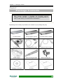
1
Preface
Preface
Notice
Product features and specifications described in this manual are subject to change without
notice.
The manufacturer shall not be liable for any damage, or for the loss of information resulting
from the performance or use of the information contained herein.
Trademarks
Accusys and the names of Accusys products and logos referenced herein are trademarks
and/or service marks or registered trademarks and/or service marks of Accusys, Inc.
Mac, Mac OS, and Macintosh are either registered trademarks or trademarks of Apple. Other
product and company names mentioned herein may be trademarks and/or service marks of
their respective owners.
All contents of this manual are copyrighted by Accusys, Inc.
The information contained herein is the exclusive property of Accusys, Inc. and shall not be
copied, transferred, photocopied, translated on paper, film, electronic media, or
computer-readable form, or otherwise reproduced in any way, without the express written
permission of Accusys Inc.
Manual version 1.0
© Copyright 2009 Accusys, Inc.
All rights reserved.
1
ExaSAN User’s Manual
About this Manual
Thank you for choosing the ExaSAN solution. This manual takes you step by step through the
installation and configuration of the ExaSAN product kit.
PART ONE:
Introduction
Chapter 1:
Introduces the features of ExaSAN.
Chapter 2:
Detailed list of package contents.
Chapter 3:
Definition of ExaSAN components.
PART TWO:
Chapter 4:
Hardware Installation
Instructions for ExaSAN installation.
PART THREE: Connections
Chapter 5:
PART FOUR:
Chapter 6:
PART FIVE:
Instructions for making connections and powering on.
RAID Configuration
Instructions for configuring arrays.
Software Installation
Chapter 7:
Instructions for software installation on Windows.
Chapter 8:
Instructions for software installation on Mac.
Chapter 9:
Introduces the G2 PCIe Switch Graphic User Interface.
PART SIX:
Appendices
Appendix A: Instructions for Xsan settings.
Appendix B: Instructions for Final Cut Pro installation.
Appendix C: Instructions for enabling root authority.
Appendix D: Contact details of Accusys business units around the world.
Guide to Conventions
Important information that users should be aware of is indicated with the following icons:
This icon indicates the existence of a potential hazard that could result
in personal injury, damage to your equipment or loss of data if the
safety instruction is not observed.
This icon indicates useful tips on getting the most from your ExaSAN
Kit.
Important terms, commands and programs are put in Boldface font.
2
Table of Contents
Table of Contents
PREFACE......................................................................................................................... 1
Notice.................................................................................................................... 1
Trademarks ........................................................................................................... 1
About this Manual ................................................................................................ 2
Guide to Conventions ........................................................................................... 2
TABLE OF CONTENTS................................................................................................. 3
PART ONE .....................................................................................................................5
INTRODUCTION..........................................................................................................5
CHAPTER 1
OVERVIEW ........................................................................................ 6
CHAPTER 2
PACKAGE CONTENTS .................................................................... 7
Kit 1 ...................................................................................................................... 8
Kit 2 ...................................................................................................................... 8
Kit 3 ...................................................................................................................... 9
Optional Items .................................................................................................... 10
What Else You Need........................................................................................... 10
CHAPTER 3 COMPONENTS................................................................................. 11
G1 Front View .................................................................................................... 11
G1 Back View..................................................................................................... 12
G1 Port Configurations....................................................................................... 12
G2 Front View .................................................................................................... 13
G2 Back View..................................................................................................... 13
G2 Port Configurations....................................................................................... 14
NT redrive card................................................................................................... 14
PART TWO ..................................................................................................................15
HARDWARE INSTALLATION ................................................................................15
CHAPTER 4
EXASAN INSTALLATION ............................................................. 16
Pre-installation Notices....................................................................................... 17
Mounting the ExaSAN system............................................................................ 18
Installing the Hard Disk Drives .......................................................................... 19
Installing the NT redrive card ............................................................................. 19
PART THREE..............................................................................................................20
CONNECTIONS ..........................................................................................................20
CHAPTER 5 CONNECTIONS ............................................................................... 21
Basic connections ............................................................................................... 22
Additional switch linkage ................................................................................... 23
Removing the External PCIe x4 Cable ............................................................... 24
Connecting to a Power Source and Powering On ............................................... 24
Powering Off ...................................................................................................... 24
PART FOUR ................................................................................................................26
3
ExaSAN User’s Manual
RAID CONFIGURATION..........................................................................................26
CHAPTER 6 RAID CONFIGURATION ............................................................... 27
Creating Arrays................................................................................................... 27
PART FIVE ..................................................................................................................30
SOFTWARE INSTALLATION .................................................................................30
CHAPTER 7 INSTALLING THE DRIVER AND RAIDGUARD X ON WINDOWS
......................................................................................................................................... 31
Windows driver &RAIDGuard X Installation .................................................... 31
CHAPTER 8 INSTALLING THE DRIVER AND RAIDGUARD X ON MAC OS
......................................................................................................................................... 32
Mac driver & RAIDGuard X Installation ........................................................... 32
CHAPTER 9 GRAPHIC USER INTERFACE ...................................................... 33
View Settings...................................................................................................... 33
Update Firmware ................................................................................................ 34
PART SIX .....................................................................................................................36
APPENDICES ..............................................................................................................36
APPENDIX A XSAN SETTINGS ........................................................................... 37
Download Xsan .................................................................................................. 37
Install Xsan2 ....................................................................................................... 37
Create new SAN ................................................................................................. 38
Kit1 RAID system settings ................................................................................. 44
Kit2/Kit3 RAID system settings ......................................................................... 45
APPENDIX B FINAL CUT PRO ............................................................................ 46
Install Final Cut Pro............................................................................................ 46
APPENDIX C
ENABLE ROOT AUTHORITY..................................................... 48
APPENDIX D CONTACT US ................................................................................. 50
Taiwan - Accusys, Inc. ....................................................................................... 50
America - Accusys U.S.A., Inc........................................................................... 50
Korea - Accusys Korea, Inc. ............................................................................... 50
China Beijing- Accusys China, Inc..................................................................... 50
Europe - Accusys EU B.V .................................................................................. 50
4
Introduction
5
ExaSAN User’s Manual
Chapter 1
Overview
This chapter introduces the features and capabilities of
ExaSAN.
The ExaSAN series provide superior functionality and performance for multiple video editing
and simultaneous High-Definition video playback. The ExaSAN series offer the following
product kits:
Kit 1
Package of one G1 PCIe switch, one 6-port G2 PCIe switch, four NT redrive
cards, and four PCIe optical cables (30m).
Kit 2
Package of one G1 PCIe switch, one 12-port G2 PCIe switch, eight NT
redrive cards, and eight PCIe optical cables (30m).
Kit 3
Package of two G1 PCIe switches, one 12-port G2 PCIe switch, eight NT
redrive cards, and eight PCIe optical cables (30m).
ExaSAN series product kits are designed for multiple and non-linear High-Definition video
editing applications, meeting extreme bandwidth demands and providing sustained read
throughput for in-time playback.
ExaSAN series provide a total PCI Express SAN (Storage-Attached-Network) turnkey solution,
bundling the HBA card, switch, and RAID system. ExaSAN enables PCIe switch linkage to
support up to 12 host servers, 28 storage ports, and 14 Dual-Independent ExaRAID HD RAID
systems.
In this document you will find detailed introductions to ExaSAN components, and instructions
for installing the hardware and software for your ExaSAN system.
6
Chapter 2 – Package Contents
Chapter 2
Package Contents
This chapter provides a checklist for ExaSAN package
contents. You will find a detailed list for each product kit, as
well as other items you will need for installation.
Depending on the model you purchased, the contents of your package may vary.
G1 PCIe Switch
G2 PCIe Switch (6-port)
G2 PCIe Switch (12-port)
NT redrive card
PCIe optical cable (30m)
External PCIe x8 Cable
Power adaptor
Rack mounting brackets
Rack mounting ears
Installation CD-ROM
G1 QSG
G2 QSG
7
ExaSAN User’s Manual
Kit 1
ExaSAN Kit1 includes the following contents:
Item
Qty
G1 PCIe switch
1
G2 PCIe switch (6-port)
1
NT (Non-Transparent) redrive card
4
PCIe optical cable (30m)
4
External PCIe x8 Cable
1
Power adaptor
2
Rack mounting brackets (set of 2)
2
Racking mounting ears (set of 2)
2
Installation CD-ROM
1
G1 QSG
1
G2 QSG
1
Kit 2
ExaSAN Kit2 include the following contents:
8
Item
Qty
G1 PCIe switch
1
G2 PCIe switch (12-port)
1
NT (Non-Transparent) redrive card
8
PCIe optical cable (30m)
8
External PCIe x8 Cable
1
Power adaptor
2
Rack mounting brackets (set of 2)
2
Racking mounting ears (set of 2)
2
Installation CD-ROM
1
G1 QSG
1
G2 QSG
1
Chapter 2 – Package Contents
Kit 3
ExaSAN Kit3 include the following contents:
Item
Qty
G1 PCIe switch
2
G2 PCIe switch (12-port)
1
NT (Non-Transparent) redrive card
8
PCIe optical cable (30m)
8
External PCIe x8 Cable
2
Power adaptor
3
Rack mounting brackets (set of 2)
3
Racking mounting ears (set of 2)
3
Installation CD-ROM
1
G1 QSG
1
G2 QSG
1
9
ExaSAN User’s Manual
Optional Items
z
z
19” rack for mounting the switch.
Screwdriver for connecting the rack mounting brackets and ears.
What Else You Need
z
z
z
z
z
Host servers with a spare PCIe x4, x8, or x16 slot.
ExaRAID HD RAID systems.
Ethernet switch and cable for SAN environment.
SAN software (Xsan 2.0 and metaSAN recommended).
Static grounding strap or electrostatic discharge (ESD) safe work area.
The PCIe slots on some motherboards are for graphics cards only.
Check with the motherboard vendor for compatibility.
10
Chapter 3 – Components
Chapter 3
Components
This chapter provides a comprehensive guide to the G1 and G2
PCIe switches, and the NT redrive card.
G1 Front View
No.
Name
Description
1
Reset button
Press with a pen tip or similar to reboot the
switch.
2
Power LED
Lit when there is power.
3
Fan LEDs
Lit when the corresponding fan fails.
4
Port LEDs
Lit when a port is connected, and flashes when a
port is accessed.
11
ExaSAN User’s Manual
G1 Back View
No.
Name
Description
1
Port LEDs
Lit when a port is connected, and flashes when a
port is accessed.
2
Ports 1-9
Connect PCIe connector cables.
3
DC connector
Connect to the power adaptor.
4
Reset button
Press with a pen tip or similar to reboot the
switch.
5
Power LED
Lit when there is power.
6
Fan LEDs
Lit when the corresponding fan fails.
G1 Port Configurations
The G1 PCIe switch has one PCIe (x8) upstream port to connect to the redrive card in the host
server, one cascade port to connect to another G1 PCIe switch, and seven PCIe (x4)
downstream ports to connect to ExaRAID HD RAID systems.
Port
12
Description
1
PCIe (x8) upstream port to connect to the redrive
card in the host server.
2
PCIe (x8) cascade port to connect to PORT1 (Host) of
another ExaSAN G1 PCIe switch.
3-9
PCIe (x4) downstream ports to connect to ExaRAID HD
RAID systems.
Chapter 3 – Components
G2 Front View
No.
Name
Description
1
Reset button
Press with a pen tip or similar to reboot the
switch.
2
Power LED
Lit when there is power.
3
Fan LEDs
Lit when the corresponding fan fails.
4
Port LEDs
Lit when a port is connected, and flashes when a
port is accessed.
G2 Back View
No.
Name
Description
1
Port LEDs
Lit when a port is connected, and flashes when a
port is accessed.
2
Cascade ports
Connect to ExaSAN G1 PCIe switch(es) (port B
only available for 12-port model).
3
Ports 1-12
Connect to host server(s) (ports 7-12 only
available for 12-port model).
4
DC connector
Connect to the power adaptor.
5
Reset button
Press with a pen tip or similar to reboot the
switch.
6
Power LED
Lit when there is power.
7
Fan LEDs
Lit when the corresponding fan fails.
8
LAN port
Connect to an RJ-45 cable for firmware upgrades
and GUI access from the host server(s).
9
Console
Used for factory repair.
13
ExaSAN User’s Manual
G2 Port Configurations
The 6-port G2 PCIe switch has one cascade port to connect to a G1 PCIe switch, and six
Infiniband upstream ports to connect to the NT redrive cards in host servers.
The 12-port G2 PCIe switch has two cascade ports to connect to G1 PCIe switches, and
twelve Infiniband upstream ports to connect to the NT redrive cards in host servers.
Port
Description
Cascade A and B
PCIe (x8) cascade port to connect to PORT1 (Host) of
ExaSAN G1 PCIe switch(es) (Cascade port B only
available for 12-port model).
1-12
Infiniband upstream port to connect to the NT redrive
card in the host server(s) (ports 7-12 only available for
12-port model).
NT redrive card
The NT redrive card is installed in the host server, and provides the interface for managing the
PCIe switches and disk arrays.
No.
14
Name
Description
1
External PCIe x4 port
Connects to the PCIe optical cable and the G2
PCIe switch.
2
PCIe x4 connector
Connects to the motherboard of the host server.
Hardware Installation
15
ExaSAN User’s Manual
Chapter 4
ExaSAN Installation
This chapter provides instructions for installing necessary
components of the ExaSAN system.
Before the ExaSAN system is ready to be connected and powered on, you must do the
following:
•
•
•
Mount the ExaSAN and ExaRAID HD RAID systems in a rack.
Install the hard disk drives with AA-MUX tray boards into the ExaRAID HD RAID
systems.
Install the NT redrive cards in the MacPro host servers.
Enterprise level SATAII drives with 7200rpm and 32MB cache are
recommended. The recommended disk model is WD1002FBYS.
16
Chapter 4 – ExaSAN Installation
Pre-installation Notices
Before starting any kind of hardware installation, please ensure that all
power switches have been turned off and all power cords disconnected
to prevent personal injury and damage to the hardware.
To avoid overheating, ExaSAN should be installed in a well-ventilated
area and in such a way that sufficient airflow is maintained across the
card chips.
Static electricity can damage electronic components. To guard against
such damage:
Work in a static-free environment.
Wear a grounded anti-static wrist strap.
Store uninstalled components in anti-static bags.
Handle PCBs by their edges and avoid touching chips and connectors.
Operating parameters
Operating temperature: 0°C to 40°C (32°F to 104°F)
Storage temperature: -40°C to 70°C (-40°F to 158°F)
Operating humidity: 5-85%, non-condensing
Storage humidity: 0-95%, non-condensing
17
ExaSAN User’s Manual
Mounting the ExaSAN system
The ExaSAN system is designed to be mounted in a standard 19-inch rack. It is recommended
that you mount the ExaSAN system before making cable connections.
To mount the PCIe switches in a rack:
1. Attach the rack mounting brackets or ears to the side of the switch as shown below.
EitR52. Secure the switch into a 19” rack using the fixtures provided.
The rack mounting ears are only available for the G2 PCIe switch.
For instructions on mounting the ExaRAID HD RAID system, see “ExaRAID HD User’s
Manual".
18
Chapter 4 – ExaSAN Installation
Installing the Hard Disk Drives
For instructions on installing the hard disk drives, see “ExaRAID HD User’s Manual".
Installing the NT redrive card
The NT redrive card is compatible with PCI Express slots x4, x8, and x16. It is recommended
to install the NT redrive card in the fastest PCIe bus (x16 PCIe bus is preferred).
Read the pre-installation notices earlier in this chapter before
proceeding.
1. Make sure the host server is turned off.
2. Open the server case.
3. Remove the blanking plate from the
PCIe slot.
4. Position the connector of the card over
the PCIe slot.
5. Press the connector of the card gently
but firmly into the PCIe slot until it is
correctly and securely seated.
6. Secure the metal bracket of the card to
the system case with a screw.
Many motherboards only come with one PCI Express interface. Before
installation, make sure there is one free.
19
ExaSAN User’s Manual
Connections
20
Chapter 5 – Connections
Chapter 5
Connections
This chapter provides instructions for making connections and
powering on the ExaSAN system.
After you have installed the necessary components, the ExaSAN system is ready to be
connected and powered on. Before powering on, you must do the following:
•
•
•
Connect the G1 PCIe switch(es) to ExaRAID HD RAID systems.
Connect the G2 PCIe switch to the G1 PCIe switch(es).
Connect the G2 PCIe switch to host servers.
Once basic connections are made, you can also connect additional G1 PCIe switches for
maximum storage expansion. The ExaSAN system supports up to four G1 PCIe switches for
additional switch linkage.
21
ExaSAN User’s Manual
Basic connections
To connect the G1 PCIe switch to ExaRAID HD RAID systems:
1. With the pull tabs facing up, insert one end of the PCIe (x4) cable into a port (3-9) on the
back of the G1 PCIe switch.
2. Insert the other end into the back of an ExaRAID HD RAID system.
To connect the G2 PCIe switch to the G1 PCIe switch:
1. With the pull tabs facing up, insert one end of the PCIe (x8) cable into Cascade port A or
B on the back of the G2 PCIe switch. Cascade ports A and B can each support switch
linkage up to two G1 PCIe switches.
2. Insert the other end into PORT1 (Host) of G1 PCIe switch.
To connect the G2 PCIe switch to the host servers:
1. Insert one end of the PCIe optical cable into a port (1-12) on the back of the G2 PCIe
switch.
2. Insert the other end into the NT redrive card installed in host server.
3. Connect all PCIe optical cables between the G2 PCIe switch and host servers.
22
Chapter 5 – Connections
Additional switch linkage
For additional switch linkage, you can connect the currently used G1 PCIe switch to another
G1 PCIe switch:
1. With the pull tabs facing up, insert one end of the PCIe (x8) cable into PORT2 (Cascade)
on the back of the G1 PCIe switch already connected to the G2 PCIe switch.
2. Insert the other end into PORT1 (Host) of another G1 PCIe switch.
23
ExaSAN User’s Manual
Removing the External PCIe x4 Cable
To remove the external PCIex4 cable, put your finger into the ring of the external PCIe x4 cable
connector and pull gently to release it.
Do NOT remove the external PCIe x4 cable forcibly in any other way,
as this will damage the cable.
Connecting to a Power Source and Powering On
1. Plug the power cables into the back of the ExaRAID HD RAID systems, and connect
the other end to a power source.
2. Press the power switch on the back of the ExaRAID HD RAID systems.
3. Plug the power adaptor(s) into the DC connector(s) on the back of the G1 PCIe
switch(es), and connect the other end to a power source. The G1 PCIe switch(es)
automatically powers on.
4. Plug the power adaptors into the DC connector on the back of the G2 PCIe switch,
and connect the other end to a power source. The G2 PCIe switch automatically
powers on.
5. When the LEDs for Cascade ports A and B on the G2 PCIe switch are lit (Cascade
port B only available for 12-port model), power on the host servers.
Before powering on, make sure the hard disk drives, NT redrive cards,
external PCIe cables, PCIe optical cables and power cables are
properly installed and connected.
Do NOT remove the cables when in use as this will cause data loss.
PCIe optical cables connected to the G2 PCIe switch and host servers
support the hot-plug function. Always reboot the host servers after hot
plugging.
24
Chapter 5 – Connections
PCIe cables connected to the G1 PCIe switch and host servers do
NOT support the hot-plug function.
Powering Off
1. Power off the host servers.
2. Unplug the power adaptor of the G2 PCIe switch from the power source. The G2
PCIe switch automatically powers off.
3. Unplug the power adaptor(s) of the G1 PCIe switch(es) from the power source. The
G1 PCIe switch(es) automatically powers off.
4. Press the power switch on the back of the ExaRAID HD RAID systems.
Unplugging the G2 PCIe switch before the host servers are powered
off causes kernel panic.
25
RAID Configuration
26
Chapter 6 – RAID Configuration
Chapter 6
RAID Configuration
This chapter provides instructions for creating the first disk
array with RAIDGuardX, mapping the array to Lun, and
selecting the setting for optimal performance.
/
Creating Arrays
Administrators can choose how best to distribute the available hard disk drives. Once an array
has been created, it can be further administered in the Options section.
Creating an Array
When the RAID controller is first configured, an array needs to be set up. This array tells the
controller how many disks to use and what their function should be. The Accusys PCIe
controllers support RAID levels 0, 1, 5, 6, 0+1 and JBOD.
Follow the steps below to create an array:
Step 1: Select the RAID level from the drop down menu. Available levels are: 0, 1, 5, 6,
0+1 and JBOD. Each level has a minimum disk requirement and this is shown
in the information to the right of the drop down list.
Step 2: Select the stripe size from the drop down menu. Available stripe sizes are:
8-256KB. The greater the stripe size, the faster the I/O output for each drive.
This speeds up disk access.
Select the sector size from the drop down menu. Available sector sizes are 512
bytes (default) and 4096 bytes. The sector size 4096 bytes is only supported
by Windows 2000/XP, and over 2 Terabyte function is used. For another OS,
please select 512 bytes (default).
Step 3: Click on the drives to be added to the array. You can also click on Select all
spare drivers.
The image displayed will vary depending on which controller is being
used.
27
ExaSAN User’s Manual
Optional: From the drop down menu, select either On the fly initialization or Performance
evaluation.
On the fly initialization – The default setting is for normal use. The data and parity will
be initialized automatically. The performance will degrade to some degree during the
initialization process.
Performance evaluation – Select to evaluate the performance of the target array. Data
and parity are not initialized. (No data protection when this mode is on)
Assign LUN automatically
Check this box to automatically assign a LUN.
Click Create Array to complete the process.
28
Chapter 6 – RAID Configuration
SAN Performance Equalization Mode
Enable this mode for maximum stability and performance in a SAN environment.
Follow the steps below to enable SAN Performance Equalization Mode:
Step 1: Select the Preferences menu, and click on the Mode tab.
Step 2: Check the box for SAN Performance Equalization Mode.
Step 3: Click OK to confirm.
For more details, see “RAIDGuardX User’s Manual”.
29
ExaSAN User’s Manual
Software Installation
30
Chapter 7 – Installing the driver and RAIDGuard X on Windows
Chapter 7
Installing the driver and
RAIDGuard X on Windows
This chapter details the installation, setup and configuration
process for RAIDGuard X on a Windows operating system.
RAIDGuard X Server must be installed on the host server.
RAIDGuard X Client must be installed on each computer that
will monitor or administer the RAID controller(s).
Windows driver &RAIDGuard X Installation
1.
2.
3.
4.
5.
Insert the CD-ROM into the CD-ROM drive of the server or PC.
Execute “CD-ROM/…/…/…/ AccusysNTSW_IP_Win_xxx_1.00.exe”.
Follow the onscreen instructions.
When installing on the host server, select Complete to install the Server and Client.
When installing on a remote computer, select Custom to choose which applications
(Client or Server) to install.
6. Click Finish to complete the installation.
7. Restart the computers.
Storport and miniport are new storage drivers created by Microsoft for
Windows Server 2003 and future Windows® operating systems.
31
ExaSAN User’s Manual
Chapter 8
Installing the driver and
RAIDGuard X on MAC OS
This chapter details the installation, setup and configuration
process for RAIDGuard X on the Mac operating system.
RAIDGuard X Server must be installed on the host server.
RAIDGuard X Client must be installed on each computer that
will monitor or administer the RAID controller(s).
Mac driver & RAIDGuard X Installation
1.
2.
3.
4.
5.
Insert the CD-ROM into the CD-ROM drive of the MAC.
Execute “CD-ROM/xxx/xxx/ AccusysNTSW_IP_MAC_1.00.mpkg”.
Follow the onscreen instructions.
When installing on the host server, select Complete to install the Server and Client.
When installing on a remote computer, select Custom to choose which applications
(Client or Server) to install.
6. Click Finish to complete the installation.
7. Restart the computers.
32
Chapter 9 – Graphic User Interface
Chapter 9
Graphic User Interface
This chapter introduces the G2 PCIe Switch GUI (Graphic User
Interface).
View Settings
In the GUI, the front and back of the G2 PCIe switch are displayed.
The G2 PCIe switch GUI uses the following settings:
Default address: https://192.168.0.1.
Default user name: admin
Default password: 0000
33
ExaSAN User’s Manual
To view detailed information, click on the G2 PCIe switch. To display configurations of a port in
an independent window, click on an Infiniband port (ports 1 to 12) on the back of the switch.
Update Firmware
You can update the firmware of the G2 switch in the Graphic User Interface.
1. In the Login information panel, enter "admin" in the Username field, and enter “0000”
in the Password field.
2. Click the Login button to enter Config Mode.
3. Select “Firmware Update”, and select the firmware type (System F/W or Boot Code).
4. Click Browse, and then select the path for the correct file.
5. Click Apply to begin the firmware update.
34
Chapter 9 – Graphic User Interface
Power off the host servers before updating the firmware. Once the
firmware update is complete, the G2 PCIe switch reboots. When the
LEDs for Cascade ports A and B on the G2 PCIe switch are lit
(Cascade port B only available for 12-port model), power on the host
servers again.
35
ExaSAN User’s Manual
Appendices
36
Appendix A – Xsan Settings
Appendix A
Xsan Settings
Xsan2.0 software enables volume sharing and allows each host server to access and
configure the RAID storage volume. This section provides instructions for utilizing a SAN
environment with Xsan2.0 management.
Download Xsan
Xsan2.0 software and trial license can be downloaded from Apple website by a registered
ADC account. For more information, see http://developer.apple.com/mac/.
Install Xsan2
1. Insert Xsan2 CD into DVD-ROM. The install window will pop-up.
2. Press the Install Xsan icon, and follow the onscreen instructions.
3. Once installation is complete, press Close to exit the application.
37
ExaSAN User’s Manual
Create new SAN
1. Double click Xsan admin in the folder Applications/server. The setup console is
opened.
2. Select “Create new SAN“.
3. Type a name for the SAN, and then enter the SAN administrator’s name and email
address.
38
Appendix A – Xsan Settings
4. In the Add Computers pane, make sure all the computers that you want to be in the
SAN are selected.
If a computer you want to include isn’t listed, make sure you have
installed Xsan on that computer, check that it is connected to both
Ethernet networks, and check the network settings in the computer’s
Network preferences. You can also click Add Remote Computer to add
computers manually.
5. In the Authenticate SAN Computers pane, select “Use same authentication
information for all SAN Computers” and enter the user account name and password
you entered on the clients and the metadata controller.
39
ExaSAN User’s Manual
6. In the Serial Numbers pane, enter your Xsan serial numbers. You can click Add
Serial Number and type a number, or drag a text file containing serial numbers to the
list.
7. In the Choose Metadata Controllers pane, select only your metadata controllers.
Deselect any client-only computers that appear in the list.
8. In the Private Metadata Network pane, select “Yes, manage private Ethernet network
settings”.
40
Appendix A – Xsan Settings
9. Review the Summary pane. If all settings are correct, click Continue.
10. In the Create Volume pane, select “Create a volume now” and click Continue.
11. In the Volume Name and Type pane, type a name for the volume and choose a
volume type that matches the type of work the volume will support.
41
ExaSAN User’s Manual
1. Click Advanced Setting to enter the setting menu, and change
“block allocation size” to 4KB to get best performance for multiple
video playback.
2. If the Label LUNs pane appears, select “Automatically label all
unlabeled LUNs with prefix” and click Continue. When the list of
labeled LUNs appears, verify the LUN labels and click Continue.
12. In the Configure Volume Affinities pane, drag LUNs from the left column to the
corresponding affinity tag in the right column. For the correct Meta-volume and DATA
volume configurations, see p.44, “Kit1 RAID system settings” and p.45, “Kit2/Kit3
RAID system settings”. When you finish, click Continue.
42
Appendix A – Xsan Settings
13. In the Setup Complete pane, click Continue. Xsan Admin displays a summary of your
SAN configuration and the new data volumes (ExaSAN) are mounted and ready to
use on all clients and meta server.
43
ExaSAN User’s Manual
Kit1 RAID system settings
These are the recommended RAID system settings for ExaSAN Kit1 in a SAN environment.
RAID
system
Controller
Disk
1~10
B
11, 12
ExaRAID HD
24 bays
1~10
A
11, 12
-RAID
RAID
Level
Slice
Array1
Slice0
Array2
1
Slice0
Array1
5
Slice0
Array2
1
Slice0
configuration table5
-Array setting layout-
-Xsan volume setting-
44
LUN
Size
SAN/DLP
0
9TB
Enable
1
1TB
Enable
0
9TB
Enable
1
1TB
Enable
Appendix A – Xsan Settings
Kit2/Kit3 RAID system settings
These are the recommended RAID system settings for ExaSAN Kit2/Kit3 in a SAN
environment.
RAID
system
Controller
ExaRAID
HD 16
bays-1
B
A
B
ExaRAID
HD16
bays-2
A
Disk
RAID
Level
Slice
Array1
Slice0
Array1
1~8
5
Slice0
Array1
1~8
5
Slice0
Array1
1~6
5
Slice0
Array2
Slice0
7, 8
1
Array2
Slice1
-RAID configuration table1~8
ExaRAID HD 16 bays-1
5
LUN
Size
SAN/DLP
0
7TB
Enable
0
7TB
Enable
0
7TB
Enable
0
5TB
Enable
1
500GB
Enable
2
500GB
Enable
ExaRAID HD16 bays-2
-Array setting layout-
-Xsan volume setting
45
ExaSAN User’s Manual
Appendix B
Final Cut Pro
Final Cut Pro enables non-linear editing from multiple host servers and delivers real-time
performance. You can use Final Cut Pro for video editing in larger workgroups and
simultaneous HD video playback.
Install Final Cut Pro
1. Insert the Final Cut Studio installation disc into your computer’s DVD drive.
2. Double-click the Install Final Cut Studio icon, and then follow the onscreen
instructions.
3. In the User Information pane, enter your first and last name (entering an organization
name is optional) and enter a valid serial number.
46
Appendix B – Final Cut Pro
Once installation is complete, you can use Final Cut Pro for simultaneous HD video playback,
as demonstrated below.
47
ExaSAN User’s Manual
Appendix C
Enable Root Authority
To enable root authority:
1. In the System Preferences pane, select “Accounts”.
2. Click Login Options, and select “Disabled” in the “Automatic login” field.
3. In the Utilties pane, select “Directory Utility”.
48
Appendix C – Enable Root Authority
4. In the menu bar, select "Edit" and “Enable Root User”.
5. Login again to root account.
49
ExaSAN User’s Manual
Appendix D
Contact Us
Taiwan - Accusys, Inc.
z
z
z
z
z
5F., No.38, Taiyuan St., Jhubei City, Hsinchu County 30265, Taiwan, R.O.C.
Tel: +886-3-560-0288
Fax: +886-3-560-0299
http://www.accusys.com.tw/
e-mail: [email protected], [email protected]
America - Accusys U.S.A., Inc.
z
z
z
z
z
z
46710 Fremont Blvd. Fremont, CA 94538, U.S.A.
Tel: +1-510-661-0800
FAX: +1-510-661-9800
Toll-free number: +1-866-277-5888
http://www.accusysusa.com/
e-mail: [email protected], [email protected]
Korea - Accusys Korea, Inc.
z
z
z
z
z
Baegang B/D 5F Shinsa-Dong 666-14 Kangnam-Gu, Seoul, Korea
Tel: +886-2-6245-9050
Fax: +886-2-3443-9050
http://www.accusys.co.kr/
e-mail: [email protected]
China Beijing- Accusys China, Inc.
z
z
z
z
z
No. 1701, Blk B, Horizon International Tower, No. 6 Zhichun Street, Haidian District,
Beijing, ZIP: 100088, China
Tel: +86-10-82800080/81/82/83
Fax: +86-10-82800784
http://www.accusys.cn
e-mail: [email protected], [email protected]
Europe - Accusys EU B.V
z
z
z
z
z
z
50
Address: Orionweg 6, 4782 SC Moerdijk, The Netherlands
Tel: +31 (0) 102995758
Fax: +31 (0) 168358621
http://www.accusyseu.com
ftp://ftp.accusyseu.com
e-mail: [email protected], [email protected]