1
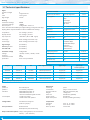
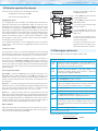
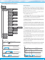
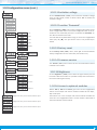
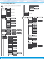
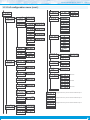
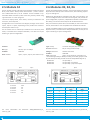
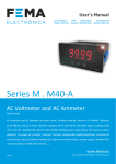
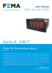
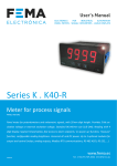
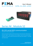
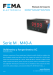
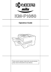
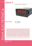
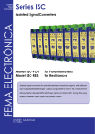
FEMA ELECTRÓNICA . Series M . M50-P
2.5 Module S2
2.6 Modules R2, R4, R6
The S2 module provides a RS-232 communications module for Series
M of panel meters. ASCII protocol with ‘Master’ / ‘Slave’ architecture. Addressable with up to 31 modules. Frames codified in representable ASCII characters (codes 32 to 255), directly visible using
‘hyperterminal’ or similar programs.
The R2, R4 and R6 modules provide 2, 4 and 6 relay outputs for Series
M panel meters. Relays with 3 contacts each, with switching capability up to 250 V @ 6 A.
• Access to display values, alarm status, memory of maximum and
minimum, alarm setpoints, ...
Configuration from instrument front keypad, through menu entries
‘Opt.1’, ‘Opt.2’ or ‘Opt.3’, depending on the position the module is
installed (see section 1.13).
The S2 module can be ordered pre-installed into a Series M panel
meter, or standalone for delayed installation, as it does not require
soldering or special configuration.
Modules R2, R4 and R6 are installed on slot ‘Opt.1’ (see section 1.13)
and are configured from instruments front keypad, and provide setpoint configuration, hysteresis, independent activation and deactivation delays, and second alarm setpoint for windowed alarms.
Only one module R2, R4 or R6 can be installed per instrument. Modules R2, R4 and R6 are not compatible with standard R1 modules.
The R2, R4 and R6 modules can be ordered pre-installed into a Series
M panel meter, or standalone for delayed installation, as they do not
require soldering or special configuration.
Protocol
ASCII
Type of relay
3 contact relay (NC, NO, common)
Bus type
RS-232, up to 57.6 Kbps
Current maximum
6 A per relay (resistive load)
Isolation
1000 Vdc
Voltage maximum*
250 Vac continuous
Slots allowed
‘Opt.1’, ‘Opt.2’, ‘Opt.3’ (see section 1.13)
Isolation
2500 Veff
Type of terminal
plug-in screw terminal, pitch 3.81 mm
* terminals approved for 300 V (according to UL1059, groups B and
D) and 160 V (according to VDE on CAT-III and pollution degree 3).
occupies Opt.1
occupies Opt.1 and Opt.2
occupies Opt.1, Opt.2 and Opt.3
Opt.1
Opt.2
Opt.1
A B C D E
A B C D E
ABCDEF
Signal
Opt.2
GHIJKL
MNOPQR
Opt.3
A B C D E
Opt.3
Module R2
Module R4
Module R6
Power
Signal
Terminal A
Terminal B
Terminal C
GND
Rx1
Tx1
Relay
Common
Terminal D
Terminal E
Rx2
Tx2
relay 1
Power
A
Normally Open
(NO)
B
Normally Closed
(NC)
C
relay 2
D
E
F
relay 3
G
H
I
relay 4
J
K
L
relay 5
M
N
O
relay 6
P
Q
R
Table 4 - Connections for modules R2, R4 and R6
For more information see document 3500_MODULE-M_S2_
manual_i.pdf
18
For more information see document 3508_MODULES-M_R2-R4-R6_
manual_i.pdf