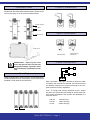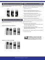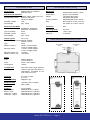
1
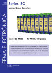
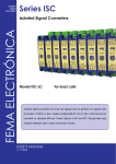
Series ISC
Isolated
Signal
Converters
FEMA ELECTRÓNICA
Isolated Signal Converters
Model ISC-POT
Model ISC-RES
for Potentiometers
for Resistances
Isolated signal converters for potentiometric and resistance signals, with different
input-output selectable ranges. Output configurable for mA or Vdc. Instrument to
be mounted on standard DIN rail. Power options in AC and DC. Strong three way
isolation between input, output and power circuits.
User’s Manual
(1194r02)
User’s Manual ISC-POT and ISC-RES
Converter ISC-POT and RES
Isolated Signal Converter for potentiometric and resistance signals
Isolated signal converters for potentiometric and resistance
signals. It covers a wide range of signal ranges, with potentiometers between 100 Ohms and 1 MOhm, and resistances
up to 10 KOhms.
Output signal configurable in 0/10Vdc, 4/20mA and other
ranges. Instrument readjustable through jumpers and span
and offset potentiometers accessible at the rear of the front
cover.
High isolation levels between the input, output and power
circuits, the instruments can be used as isolators between
circuits together with the signal converter functionality.
The isolation provided prevents the propagation of transient
peaks and energy discharges between circuits, thus protecting the remote acquisition systems. It also minimizes loop
grounds, which if acquired with the signal, are very difficult
to isolate.
Power option in AC and DC. Instrument to be mounted on
standard DIN rail. Connections with plug-in screw terminals.
For industrial applications.
Order Reference
Model
ISC
-
POT
-POT
-RES
-
Power
Input
0
0/100%
-0 (230 Vac 50/60 Hz)
-1 (115 Vac 50/60 Hz)
-6 (24 Vdc isolated)
Output
=
-0/100%
-0/75%
-0/10KOhms
-0/3KOhms
-...
4/20mA
-4/20mA
-0/10Vdc
-...
Precautions on installation
Risk of electrical shock. Instrument terminals can be connected
to dangerous voltage.
Instrument protected with double isolation. No earth connection
required.
Instrument is in conformity with CE rules and regulations. See
“CE Declaration of Conformity” further in this document.
This instrument has been designed and verified according to the 61010-1
CE security regulation, and is designed for applications on industrial environments. See the “CE Declaration of Conformity” further in this document for
information on the category of measure and the degree of pollution levels
that apply.
Installation of this instrument must be performed by qualified personnel
only. This manual contains the appropriate information for the installation.
Using the instrument in ways not specified by the manufacturer may lead
to a reduction on the specified protection level. Disconnect the instrument
from power before starting any maintenance and / or installation action.
The instrument does not have a general switch and will start operation as
soon as power is connected. The instrument does not have protection fuse,
the fuse must be added during installation.
The instrument is designed to be panel mounted. An appropriate ventilation
of the instrument must be assured. Do not expose the instrument to excess
of humidity. Maintain clean by using a humid rag and do NOT use abrasive
products such as alcohols, solvents, etc.
General recommendations for electrical installations apply, and for proper
functionality we recommend : if possible, install the instrument far from
electrical noise or magnetic field generators such as power relays, electrical motors, speed variators, ... If possible, do not install along the same
conduits power cables (power, motor controllers, electrovalves, ...) together
with signal and/or control cables.
Before proceeding to the power connection, verify that the voltage level
available matches the power levels indicated in the label on the instrument.
In case of fire, disconnect the instrument from the power line, fire alarm
according to local rules, disconnect the air conditioning, attack fire with
carbonic snow, never with water.
FEMA ELECTRÓNICA - Page 2
User’s Manual ISC-POT and ISC-RES
Instrument View
Output Connections
To access the jumpers for input and output range selection,
and the span and offset adjust potentiometers, open the front
cover by pressing on the A-A points indicated below.
J1
J2
J3
J4
J5
J6
J7
J8
J9
J10
J11
J12
Output Jumpers
Pot. Span
Pot. Offset
Input Connections
Input Jumpers
Front Cover
Connections for
potentiometers
Power Connections
IMPORTANT - Opening the front
cover may grant access to areas with
dangerous voltages. Operation must
be performed by qualified personnel
only.
Mounting
1 2 3
Install the instrument in vertical position, as indicated below.
To help dissipate the heat, a free space of 2mm must be left
available on both sides of the instrument.
Connections for
resistances
~
+
~
-
Earth connection - Although a terminal is offered for earth
connection, the connection is optional. The instrument does
not need this connection for correct functioning nor for compliance with the security regulations.
Fuse - To comply with security regulation 61010-1, add to
the power line a protection fuse acting as disconnection element, easily accessible to the operator and identified as a
protection device.
230 Vac
115 Vac
24 Vdc
70mA time lag
100mA time lag
250mA time lag
2 mm
FEMA ELECTRÓNICA - Page 3
User’s Manual ISC-POT and ISC-RES
Output range selection Jumpers
Readjustment procedure
Place the jumpers in the appropriate position to select the
desired output signal range.
To change the input/output relation of the instrument, select
the appropriate jumper positions for input and output, and
recalibrate the instrument as described below :
4/20 mA
0/20 mA
0/10 Vdc
1- Open the front cover
0/1 Vdc
2- Select the appropriate output range jumpers
(Section “Output range selection Jumpers” in page 4)
J1
J2
J3
3- Select the appropriate input range jumpers
(Section “Input range selection Jumpers” in page 4)
J4
J5
J6
4- Connect a signal generator to the input terminals
(Section “Input Connections” in page 3)
Input range selection Jumpers
Place the jumpers in the appropriate position to select the
desired input signal range.
5- Connect a multimeter to the output terminals
(Terminals 4 and 5 for mA or terminals 4 and 6 for Vdc)
(Values in brackets are examples for an input/output adjustment of 0/100%=0/10Vdc)
6- Generate the lower input signal (0%)
Operate the Offset potentiometer, until the output is at the
low output value desired (0Vdc)
Ranges for potentiometers (ISC-POT)
100%
50%
25%
12.5%
J7
J8
7- Generate the higher input signal (100%)
Operate the Span potentiometer, until the output is at the
high output value desired (10Vdc)
8- Repeat steps 6 and 7, until the desired accuracy is reached
J9
9.- Close the front cover
J10
J11
J12
IMPORTANT - Opening the front
cover may grant access to areas with
dangerous voltages. Operation must be
performed by qualified personnel only.
Ranges for resistances (ISC-RES)
10KOhms
5KOhms
3KOhms
1,5KOhms
J7
J8
J9
J10
J11
J12
FEMA ELECTRÓNICA - Page 4
User’s Manual ISC-POT and ISC-RES
Technical Data (cont.)
Technical Data
Input signals
Potentiometer or resistance
(different units)
Potentiometer (ISC-POT)
Selectable input ranges 0/100%, 0/50%, 0/25%, 0/12.5%
Potentiometer values
minimum 100 Ohms
maximum 1MOhm
Excitation voltage
1Vdc
Overvoltages
max. 15Vdc
Mechanical
Mounting
Connections
Weight
Housing material Size
standard DIN rail (35 x 7,5mm)
plug-in screw terminals
120 grams (DC power)
200 grams (AC power)
Polyamide PA6 UL94 V-2 blue
DC models 22.5 x 93 x 110 mm
AC models 37.0 x 93 x 110 mm
Resistance (ISC-RES)
Selectable input ranges
Type of measure
Excitation current
Overvoltages
Protection IP30
Operating Temp.
Storage Temp.
Warm-up 0 to 60ºC
–20 to +70ºC
15 minutes
0/10KOhms, 0/5KOhms,
0/3KOhms, 0/1.5KOhms
2 wire
0.2mA
max. 15Vdc
Output signals
Vdc or mA
Selectable output ranges4/20mA, 0/20mA
0/10Vdc, 0/1Vdc
Typeactive
Maximum output
22mA in current ranges
11Vdc in voltage ranges
Minimum output
-1.5mA in current ranges
-1Vdc in voltage ranges
Minimum load in Vdc
>1 KOhm
Maximum load in mA
<400 Ohms
Power
in AC
in DC
Consumption
Configuration
Mechanical Dimensions (mm)
DC powered
units
24 Vdc
AC powered
units
~
0 Vdc
~
321
230Vac 50/60 Hz
115Vac 50/60 Hz
24Vdc ±10% isolated
<3.8VA
110 mm
(4.33’’)
input and output range selection
jumpers, and span and offset potentiometers, accessible at the
rear of the front cover
Accuracy0.2% F.S. at 25ºC
Linearity0.1% F.S.
Thermal stability
250ppm/ºC typ.
Width for AC powered
units
Response time
Bandwidth
<70mSec. (90% of signal)
20Hz (-3dB)
Isolation
Input - Output
Power - Input
Power AC - Output
Power DC - Output
3 way isolation
3500Veff (60 sec.), optical
3500Veff (60 sec.), galvanic
3500Veff (60 sec.), galvanic
1000Veff (60 sec.), galvanic
Width for DC powered
units
93mm
(3.66’’)
37mm (1.46’’)
FEMA ELECTRÓNICA - Page 5
22.5mm (0.87’’)
User’s Manual ISC-POT and ISC-RES
CE Declaration of conformity
Manufacturer FEMA ELECTRÓNICA, S.A.
Pol. Ind. Santiga - Altimira 14
E08210 - Barberà del Vallès - BARCELONA
ESPAÑA - SPAIN
www.fema.es - [email protected]
Security EN61010-1
Equipment “Fixed”, “Permanently connected”
Degree of pollution 1 and 2 (without condensation)
Isolation Double
Category CAT-II
Series - Models
ISC
P, PT100, TJ, TK, TE, TT, TR, TS, VAC, VDC,
IAC, IDC, POT, RES, HZ, LC
Immunity:
EN 50082-2, IEC 1000-4-2, EN 61000-4-2,
IEC 801-2, ENV 50140, EN 61000-4-4, IEC
801-4 (level 3), ENV 50204 (level 3)
The manufacturer declares that the instruments indicated
comply with the directives and rules indicated below.
Emission
EN 50081-2, EN 55011, EN 55014, EN 55022,
European directive for low voltage D73/23/CEE amended
by D93/68/CEE.
European directive for product safety D92/59/CEE
Electrotechnical regulation for low voltage (RBT) ITC 21,
ITC 29, ITC 35.
European directive for electromagnetic compatibility D89/336/
CEE amended by D93/68 CEE
UNE 21352-76: CEI 359-71 Operating quality expressions for
electronic equipment. UNE 20652-80: CEI 284-68 Behavior
rules inherent to the handling of electronic equipment and
other similar technics.
Barberà del Vallès, 2002
Daniel Juncà - Quality Manager
Warranty
All instruments are warranted against all manufacturing
defects for a period of 24 MONTHS from the shipment date.
This warranty does not apply in case of misuse, accident or
manipulation by non-authorized personnel. In case of malfunction get in contact with your local provider to arrange for
repair. Within the warranty period and after examination by
the manufacturer, the unit will be repaired or substituted when
found to be defective. The scope of this warranty is limited to
the repair cost of the instrument, not being the manufacturer
eligible for responsibility on additional damages or costs. .
FEMA ELECTRÓNICA - Page 6
T
H
IS
S
E
C
T
IO
N
B
L
A
N
K
User’s Manual ISC-POT and ISC-RES
FEMA ELECTRÓNICA - Page 7
other products
Panel Meters
Standard 96x48 mm
Panel Meters
Small 72x36 mm
Panel Meters
Miniature 48x24 mm
Large Displays
60 & 100 mm digit
Signal Converters
& Isolators
Panel Meters
Standard 96x48 mm
www.fema.es
ELECTRONIC INSTRUMENTATION FOR INDUSTRY
FEMA ELECTRÓNICA, S.A.
Pol. Ind. Santiga - Altimira 14
E08210 Barberà del Vallès - BARCELONA
ESPAÑA - SPAIN
Tel. (+34) 93.729.6004- www.fema.es
Fax (+34) 93.729.6003- [email protected]