1
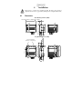
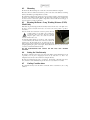
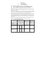
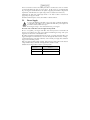
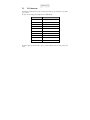
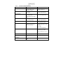
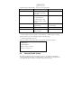
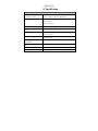
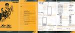
USER MANUAL
VLX1 LED Line Lighting
Revision 4
Gardasoft Vision Ltd
Castle Acres, Elsworth
Cambridge, CB23 4JQ. UK
Tel: +44 1954 200343
Fax: +44 1954 204343
Web: www.gardasoft.com
1
Disclaimer
Except as prohibited by law:
All hardware, software and documentation are provided on an “as is” basis.
It is essential that the user ensures that the operation of the product is suitable for their
application.
The user must ensure that incorrect functioning of this equipment cannot cause any
dangerous situation or significant financial loss to occur.
Gardasoft Vision Ltd and Gardasoft Products Ltd will not accept any liability for
consequential loss of any kind.
All trademarks acknowledged. Hardware, software and documentation are Copyright 2002 –
2010 Gardasoft Products Ltd. Hardware manufactured by Gardasoft Vision Ltd under licence.
2
Getting Started
Read Section 3 on Safety. Ensure that the light can be used in a safe way.
Mount the light (Section 4). Connect the light up (Section 5).
Set up the VLX1 for the desired operation – See “Configuration” (Section 6).
Visit www.gardasoft.com for application notes on this product. There is also a Support page
which has information on troubleshooting problems.
3
Safety
Read this before using the VLX1. Always observe the following safety precautions. If in doubt,
contact your distributor or Gardasoft Vision. Refer to the label on the light and any supporting
documentation supplied with the light.
Where this symbol appears in the manual, refer to the text for precautions to be
taken.
3.1
Eye Safety
It is recommended that if the light source is installed such that there is the possibility
of the personnel being directly exposed to the light output (for example, during
maintenance) an interlock is fitted to shut the light off in this instance.
3.2
Heat
The VLX1 can dissipate up to 240W per metre (convection cooled model) during
operation. In the event of a malfunction, it could get hot and should therefore be
positioned where personnel cannot accidentally touch it and away from flammable
materials.
Read the Mounting (Section 4). Do not exceed the power ratings given in the manual. Note that
at the maximum ratings the case temperature can reach >65oC.
3.3
Electrical
The VLX1 does not have complete tracking isolation of inputs and outputs. The
chassis of the VLX1 unit is at Power Supply Ground potential.
3.4
General
The VLX1 must not be used in an application where its failure could cause a danger to personal
health or damage to other equipment.
If the equipment is used in a manner not specified by the manufacturer, the protection provided
by the equipment may be impaired.
4
Installation
Read Section 3 on Safety before installing the light. The light source generates a
significant amount of heat - approximately 240W per metre of length at full intensity.
4.1
Dimensions
Short Working Distance (SWD)
90,3
36
19
Working Distance ~37mm
Line Length + 20mm i.e. 300mm Line = 320mm
20.5
41
10mm Adjustment
Long Working Distance (LWD)
124,3
134,3
1,2
16 25
90,5
6
Working Distance ~90-125mm
Lens "Focus" Adjustment
(Grub Screws - 1.5mm Allen Key)
19,3
41
4.2
Mounting
The unit has two M5 mounting holes on each end as shown in the Dimensions diagram.
Please Note: There is a difference between the positions of the holes on the SWD (short working
distance) and LWD (long working difference) variants.
The maximum useable intensity will depend on the mounting orientation, ambient temperature
and degree of air circulation around the units. The unit can be mounted in any orientation but,
for the convection cooled model, optimal cooling will be achieved with the lens facing up or
down. See below for cooling considerations.
4.3
Focusing the Beam – Long Working Distance (LWD)
Model Only
LWD units are generally shipped with the lens fully retracted into the body of the light source.
In order to operate correctly the lens needs to be moved to the correct position to produce a
focused line.
Once the unit has been mounted in its desired position, the focus
(working distance) of the VLX1 can be adjusted by
moving the position of the lens. The lens is clamped
using two “grub” screws, one at each end of the lens
accessed via holes in the covers.
To adjust the working distance, loosen the two “grub” screws using
a 1.5 mm Allen key and slide the lens in and out to achieve the
required focus. The line width can also be changed by the same
means. Once the desired setting has been achieved, clamp the lens
by lightly tightening the “grub”” screws again. Ensure that the lens has been positioned evenly
to ensure a consistent line width and intensity.
DO NOT OVER-TIGHTEN THE SCREWS OR THE LENS WILL BECOME
DAMAGED.
4.4
Setting the Line Intensity
The intensity of the light source can be set by means of the built in serial communications port. It
is generally set to 1% prior to shipping but can be set any value from 1 to 140% – See
Configuration (Section 6) for the commands for setting the intensity.
The units are generally shipped preset to 1% intensity. The intensity of the light source can be
set by means of a serial communications port and can be set to any value from 1 to 100%.
4.5
Cooling Considerations
The maximum intensity level that will be achievable will be determined by the cooling
conditions.
The VLX1 light source generates heat as do all high power LED light sources and relies on
radiation from its heat sink fins to cool the unit. The efficiency of this cooling will depend on a
number of factors.
As with all LED based light sources, the higher the operating-temperature of the
LEDs, the more quickly the intensity will reduce over time. For this reason, the
installation should aim to keep the light source as cool as possible.
The VLX1 unit has on-board temperature measurement and will shut itself down if the
temperature of the LEDs exceeds a preset threshold. Additionally, the temperature limit is
factory-set to ensure that there is no danger of personnel being burned by touching the heat sink.
This temperature setting can be modified by Gardasoft Vision under certain circumstances.
The following factors will all influence the efficiency of the cooling and therefore in combination
will ultimately determine the maximum intensity at which the unit can be used without it shutting
down.
4.5.1
Mounting Orientation
If no forced air movement is provided, the best orientation for cooling is either with the light
output directly down or up or the VLX1 unit mounted with the line vertical. This allows the
greatest convection airflow over the heat sinks.
4.5.2
Ambient Temperature
The temperature of the air around the VLX1 unit is a major factor that will influence the
efficiency of the cooling. The warmer the ambient air, the less efficient the cooling will be.
4.5.3
Local Ventilation
If the VLX1 unit is mounted in an enclosed housing, convection air flow will be very limited and
heat will only be transferred from the unit by conduction from the housing around the unit. This
will cause the unit to trip on over temperature limit (and start flashing) at much lower brightness
levels.
4.5.4
Assisted Air Movement
The cooling efficiency can be further improved by creating air movement around the heat sinks.
This can be achieved by use of fans blowing air onto the heat sink and will result in the ability to
run at higher intensities providing the local air is cool enough.
4.5.5
VLX1 “Forced Air” Variant
There is the option for the fitting of forced air cooling hardware to the VLX1 for certain lengths.
This improves the airflow through the unit allowing higher output intensities to be achieved.
Contact your distributor or Gardasoft Vision for more details.
4.6
Fault Detection
The VLX1 unit monitors the system temperature to detect if the unit is overheating. As
mentioned above, the running temperature of the unit is influenced by a number of conditions.
In the event of an over-temperature fault being detected, the unit will go into “Alarm Mode” and
the light output will be automatically shut down to indicate the fault condition. The light source
will remain in “Alarm Mode” until either the power to the unit is cycled or the Reset (Q)
command is sent via the RS232 Port (see Section 8 on Configuration).
The cause of the alarm can be determined by either using the “E” command which will return a
string describing the fault (e.g. VLX1 Over Temperature!) or the “Z” which returns a single
character numeric code (for use with bespoke software) representing the unit status.
If the option is fitted, the “Healthy” output will switch state if the unit goes into “Alarm Mode”.
4.6.1
Over-temperature
If an over-temperature Alarm occurs, ensure that the cooling arrangement is checked before
resetting the unit immediately once the power has been cycled and take appropriate action if
necessary.
The Shut Down temperature is factory preset for operating in a “normal” ambient environment
(<30oC). However, it can be changed using RS232 commands. Please consult your distributor or
Gardasoft Vision if it is believed that this could be necessary.
5
Connections
See the Specification (Appendix A) for information on connection ratings.
5.1
Power Supply Voltage and Current Requirements
Refer to the label on the light and any supporting documentation sent with the light
Although the VLX1 is quoted as nominally as being a 24DC device, due to the wide range of
LED types now available there are some differences in the best supply voltage required
depending on the wavelength.
The intensity also has an affect on the voltage required by the LEDs. In order to minimize the
“wasted” energy, some additional data sheets have been issued giving guidelines about what
supply voltage is optimal for particular LED types for specific output intensity settings.
NOTE: - This changing voltage is not the method used for regulating the intensity – the light
sources all have current control circuitry as required by LED devices. However, if the supply
voltage is significantly higher that is necessary then the additional (“spare”) voltage has to lost in
the current control electronics which is both wasteful and generates additional heat which must
then be removed.
The table below shows supply guidelines but please refer to the label on the unit before use as
LED technology is continually developing and these specifications could change.
5.1.1
General Power Supply Guidelines
DC Supply Voltage
(versus intensity setting)
Current @
Maximum Output /
125mm
Example
Current for
500mm Long
Unit*
<50%
50100
%
>100%
White, Blue, Green
LEDs Red 625nm,
UV 400nm
21V
23V
24V
1A / 100mm plus
0.5A
5.5A
Red (Deep) 660nm,
IR (Cherry Red)
740nm
16V
17V
18V
1A / 100mm plus
0.5A
5.5A
Colour
Wavelength
/
* This is independent of the supply voltage
If it is not intended to run the unit at full power then, as described above, there are benefits
associated with running the supply at a lower voltage. For this reason, it is recommended that
the power supply used with the unit is both capable of supplying the maximum voltage/current
requirements of the unit but also the output voltage can also be adjusted down if necessary.
Additionally, the VLX1 units require high currents so care must be taken to ensure that an
appropriate power supply is selected.
For further information please contact your distributor or Gardasoft Vision.
5.2
Power Supply
To avoid a fire hazard from the VLX1 or the power supply consider the implications
of overheating in the unlikely event of a fault in the VLX1. The power dissipation in
the VLX1 in a fault condition can be up to:
<Power supply voltage> * <max current delivered by power supply>
The chassis of the VLX1 unit is at Power Supply Ground potential.
The use of a regulated power supply with 100% short circuit protection is recommended. If
however a non-regulated power supply is used, then the maximum ripple voltage of this power
supply must not exceed 10% of the actual DC value.
The VLX1 is intended for industrial applications in a closed or protected environment. DC power
supply cable length is recommended not to exceed 3m. If longer DC cables are fitted, or if surge
or transient interference greater than +/-60V may occur on the DC power supply lines, additional
surge protection should be provided.
Route low voltage and mains wiring separately. If they must be loomed together ensure that low
voltage insulation rating is sufficient or that supplementary insulation is used.
Standard units are shipped with a “wired in” power input cable.
Core Colour
Function
Brown
Power 24VDC nom. See text
Blue
Power Ground
5.3
IO Connector
Communications with the unit is made via a flying lead with a 10 way “Buccaneer” style multipole connector
The IO connector mating part is Bulgin Buccaneer PX0410/10P.
Pin
Function
1
RX (input to light)
2
TX (output from light)
3
RS232 GND
4
Reserved - Do Not Connect
5
Reserved - Do Not Connect
6
Reserved - Do Not Connect
7
Reserved - Do Not Connect
8
Reserved - Do Not Connect
9
Reserved - Do Not Connect
10
Reserved - Do Not Connect
The unit is supplied as standard with a “cable to a standard RS232 serial port 9 Pin “D Type” line
socket.
6
Configuration
The VLX1 is configured using the RS232 interface.
6.1
RS232 Communication
When using RS232 the COM port should be set to 57600 Baud, 8 data bits, 1 stop bit, no parity,
and no handshaking.
The RS232 connector is a standard 9-way female D-type. A standard straight through cable can
be used to connect the controller to a PC serial port.
6.2
HyperTerminal
If using HyperTerminal to communicate with the VLX1, ensure that the following are both
selected:
Send line ends with line feeds
Echo typed characters locally
This is set on the Properties dialog, Settings tab, and ASCII Setup dialog.
Also ensure that handshaking is turned off.
To test the RS232 link, press Enter and check that an “OK” message is returned by the VLX1.
6.3
Command Structure
The intensity of the light source can be set and stored by means of a serial communications port.
It is generally set to 1% prior to shipping but can be set any value from 1 to 140% (110% for Red
& Red/Orange).
Any serial communications software (e.g. HyperTerminal supplied with MS Windows) can be
used to set the light level. The settings and commands available are as follows: The standard commands are given below. Commands are not case sensitive.
The Enter key or Linefeed (<LF>) character must be sent after each command. The VLX1 will
reply with an echo of the command given, “OK” if a “Blank” command is sent or an error
message.
6.3.1
General Command Functions
Command Syntax
Function
Response Format
?
On Screen Help - Lists
available commands
Multi Line Help Text
R <CR><LF>
Read current intensity level
percentage
Rxxx<CR><LF> – where xxx
is current output intensity
Wxxx<CR><LF>
Set the intensity level
percentage. Where:
Wxxx<CR><LF> – where
xxx is new output intensity
xxx = intensity % from 0 to
140
S<CR><LF>
Store the current intensity as
the power-up default
Sxxx<CR><LF> - where xxx
is current output intensity
T<CR><LF>
Read the VLX1 temperature
Txx<CR><LF> – where xx is
the temperature in DegC
E<CR><LF>
Read any error messages –
Returns Text String
E“string” <CR><LF> - where
“string” =
VLX1 OK
VLX1 Over Temperature
Z<CR><LF>
Returns the Unit Status
Zxx<CR><LF> – where xx is
the status code. 0 = OK.
Refer to Gardasoft for other
codes.
X0<CR><LF>
Turn light output off
X0<CR><LF>
X1<CR><LF>
Turn light output on (Default
is on)
X1<CR><LF>
Q<CR><LF>
Reset firmware and restart the
light
Q1<CR><LF>
Commands Intensity Profile Setting – See below for more information.
Command Syntax
Function
Response Format
!
On Screen Engineering Help Lists available engineering
commands
Multi Line Help Text
Oa,n<CR><LF>
Write Segment Offset
Oa,n<CR><LF>
a = segment address *
n = Offset Value 0 – 255.
Offsets are added to overall
set point
Pa<CR><LF>
Pa Read Segment Offset. A =
segment address.
Pa,n<CR><LF>
$ <CR><LF>
Store Offsets.
$1 <CR><LF>
=<CR><LF>
Returns information including
values of Offsets
See below
n = Offset Setting
* - Segment Addresses start from 0 at the coolant connections i.e. 300mm long has 9 segments
numbered from 0 to 8 from the end furthest away from the cable entries
“=” Command Typical Response below
Values after “Offsets” give the offset value of each segment starting with Segment 0
3 LED Modules
3 Therm Modules
Offsets: 0 0 0 0 0 0 0 0 0
0 0 0 0 0 0 0 0 0 etc.
6.4
Intensity Profile Setting
The intensity profile can be changed by applying “offsets” to the intensity level at different
points along the length of the line. A typical application of this would be to compensate for the
loss of light at the edges of the field of view due to camera optics / geometry.
Offsets can only be positive – i.e. they can only increase the intensity level above the “base”
value. For this reason, the point in the intensity profile which requires the lowest intensity
should have an offset of 0 with increasing offsets in other places.
The line is divided into “segments” of ~33mm – i.e. there are three segments per 100mm of
length, the incremental length of the VLX1 range. Segment Addresses start from 0 at the coolant
connections i.e. 300mm long has 9 segments numbered from 0 to 8 from the end furthest away
from the cable entries.
The commands used for setting the offsets are shown in the table below. The offset value can be
from 0 – 255. For the VLX1 range each offset unit is equivalent to around 0.3% of the
maximum intensity. NOTE: Offsets are absolute and not applied in proportion to the running
intensity
6.4.1
Example
To create a “smile” type intensity profile (i.e. higher intensity on each end on the line) on a
300mm long line the following values might be used for the 9 “segments” available: 30, 25, 20, 10, 0, 10, 20, 25, 30. These would be set to each segment in turn using the commands
in the table above.
e.g.
O0,30<CR><LF> sets segment 0 to 30 offset
O1,25<CR><LF> sets segment 1 to 25 offset
…..
O8,30<CR><LF> sets segment 8 to 30 offset
Once all the segment offsets have been set and the desired profile has been created, use the “$”
command to store these. If the dollar command has not been used, the offset values can be set
back to 0 by cycling the power to the unit.
To view the current offset values, use the “=” command as described above.
A. Specification
Light Source
Model Numbers (yyy = length
in 125mm increments)
VLX1-yyy-SWD-x (37mm working distance)
Line Colour (x)
W - white, G - green, B - blue, R – red,
VLX1-yyy-LWD-x (110mm working distance)
IR740 - infrared
UV400 – ultraviolet
Illuminated Line Length
100mm upwards in 100mm increments
Uniform Intensity Length
(>95%)
Along illuminated length – 30mm
Supply Voltage
24V nominal (16 - 24VDC typ); (15 – 28V absolute max
range) See section 5.
Current Consumption
1A / 100mm plus
wavelength/colour
Working Distance (depends on
model number)
37mm or 110mm for focused line – See model number
Colour Temperature (White
Only)
~5500oK
Intensity Control Method
RS232 - see text for commands (Ethernet module optional)
Dimensions
See “Light Source Dimensional Data” section
0.5A
depending
on
LED
Gardasoft LED Lighting Controllers
The products available at the time of writing include the following. Other products are also
available. See www.gardasoft.com for details of the current range.
RT Range
•
•
•
•
2,4 or 8 output channels up to 20A each
2,4 or 8 trigger inputs
Front panel, RS232 or Ethernet configuration
Fast pulsing option
RT200-20
RT220-20
RT260-20
RT420-20
RT820F-20
RT860F-20
Lighting controller: 2 channels up to 20A pulsing, front panel
Lighting controller: 2 channels up to 20A pulsing, Ethernet
Lighting controller: 2 channels up to 20A pulsing, RS232
Lighting controller: 4 channels up to 20A pulsing, Ethernet
Lighting controller: 8 channels up to 20A fast pulsing, Ethernet
Lighting controller: 8 channels up to 20A fast pulsing, RS232
PP704
DIN Rail mounting clip for RT range
Machine Vision Timing Controller
CC320 Controller
•
•
•
•
•
•
8 digital inputs
8 digital outputs
1 or 2 wire Encoder input
Very flexible operation
Ethernet control
Front panel configuration
PP703: DIN Rail mounting clip for CC320
Gardasoft LED Lighting
The products available at the time of writing include the following. Other products are also
available. See www.gardasoft.com for details of the current range.
VLX1 LED Line light range
•
•
•
•
•
•
High intensity LED line lights for line scan applications
Brightness up to 1.6 MLux
Line lengths from 125mm to 2 metres+
Range of wavelengths available
Forced air cooling options for increased performance
50,000+ hours service life
VLX1 LED Line light range
•
•
•
•
•
•
Very high intensity LED line lights for line scan applications
Water cooled for high efficiency cooling and long LED lifetime
Brightness up to 2.3 MLux
Line lengths from 100mm to 2 metres+
Range of wavelengths available including UV and IR
50,000+ hours service life
VTR1 & VTR2 LED Strobe lights for traffic monitoring/ANPR/LPR
•
•
•
•
•
•
•
High intensity LED strobe lights for automatic license plate recognition applications
Available in 740nm, 850nm and 940nm IR and white light
High speed strobing, up to 65Hz (VTR2)
Strobing can be asynchronous or free running
Compact IP66 rated enclosures for outdoor use
Excellent thermal management of LEDs ensuring long life service
Full intensity control for dynamic brightness adjustment