1
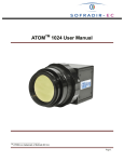
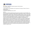
USER MANUAL
VTR2 Strobe Light
Revision 2k
Gardasoft Vision Ltd
Castle Acres, Elsworth
Cambridge, CB23 4JQ. UK
Tel: +44 1954 200343
Fax: +44 1954 204343
Web: www.gardasoft.com
2
1
Disclaimer
Except as prohibited by law:
All hardware, software and documentation is provided on an “as is” basis. This information
is for guidance only. Installers must perform their own risk assessment specific to each
installation.
It is essential that the user ensures that the operation of the product is suitable for their
application.
The user must ensure that incorrect functioning of this equipment cannot cause any
dangerous situation or significant financial loss to occur.
Deliberate acts of endangerment and vandalism are not covered by this document and must
be considered by the installer.
While care has been taken in the preparation of this document Gardasoft Vision Ltd and
Gardasoft Products Ltd will not accept any liability for consequential loss of any kind
except those required by law.
All trademarks acknowledged. Hardware, software and documentation are Copyright 2002 –
2010 Gardasoft Products Ltd. Hardware manufactured by Gardasoft Vision Ltd under licence.
3
2
Getting Started
Read the sections on Safety (Sections 3 and 4) and Specifications (Appendix A) and check the
VTR2 fulfils your requirements. See the back cover for other Gardasoft Vision strobe lights.
Mount the VTR2 as described in Section 4. Connect the VTR2 up to a supply as described in
Connections (Section 5). Set up the VTR2 for the desired operation as described in Configuration
Commands (Section 9).
Visit www.gardasoft.com for application notes on this product. There is also a Support page
which has information on troubleshooting problems.
2.1
Summary of Features
Throughout this manual, references to the VTR2 refer to all variants in the VTR2 range unless
otherwise stated. The convention for the part number is:
VTR2-www-aa-ccc
where:
www
aa
ccc
-T06
-T07
Wavelength of light in nanometres: 740, 850, 940, WHITE
Beam angle in degrees: 12 or 30
Communications: ETH, RS232, RS422
Optional suffix for trigger input option
Optional suffix for trigger output option
4
3
Safety
Read this before using the VTR2. Always observe the following safety precautions. If in doubt,
contact your distributor or Gardasoft Vision. The following symbols mean:
Warning: read instructions to understand possible hazard
Warning: Possible hazardous voltage
Warning. Surface may get hot
Where these symbols appear in the manual, refer to the text for precautions to be taken.
3.1
Heat
The VTR2 can dissipate up to 40W and so can get hot. It should be positioned where
personnel cannot accidentally touch it and away from flammable materials.
Read the Mounting (Section 4). Do not exceed the power ratings given in the manual. Note that
at the maximum ratings the case temperature can reach 65oC.
3.2
Electrical
The internal circuit exceeds 46.7V but should not exceed 60V. Pulse peak voltages
above 46.7V are considered hazardous. Do not have the cover removed with the
power on. Do not open the cover within 1 minute of turning the power off.
The VTR2 does not have complete tracking isolation of inputs and outputs.
3.3
General
The VTR2 must not be used in an application where its failure could cause a danger to
personal health or damage to other equipment.
If the equipment is used in a manner not specified by the manufacturer, the protection provided
by the equipment may be impaired.
5
4
VTR2 Safety Guidance
This guidance below applies to a single VTR2 light. For VTR2 lights with a beam angle wider
than 12 degrees, the power density will be less so again the recommended hazard distance above
is a safe assumption.
High levels of artificial optical radiation can cause damage to both eyes and skin.
Exposure limit values have been drawn up for such hazards. Every light system is
placed within a Risk Group, which defines the level of risk when the light is used
normally. When the light emits less than the exposure limit values it is categorized as exempt.
As the VTR2 light systems exceed exposure limits at certain distances and illuminate their
targets intentionally for a short time they are placed in Risk Group 1.
The hazard distance is the point furthest from the light at which the exposure limit is exceeded.
Generally the hazard distance becomes smaller either as the light power output decreases or the
less time one is exposed to the light.
When used to illuminate targets for speed cameras, the risk assessment has taken into account the
position of drivers and pedestrians and the likely times that they may be within the light beam.
This includes abnormal situation such as cars queuing for long periods due to traffic conditions
For IR models the light output is not visible and thus the aversion response does not
automatically protect the eye. These models are all classified as Risk Group 1, when the
guidance given here is followed.
The primary radiation hazard is the corneal/lens infrared hazard between 720 and 960nm.
When installed as detailed below there is no risk to the public. If it is necessary to have the light
operating whilst being within 0.5m of the lightface, use appropriate eye protection.
Development engineers and field maintenance staff should be given safe procedures for working
with the VTR2 light. This guidance assumes that staff working on the light system has been
instructed in optical radiation hazards. To allow access to the light within the beam a working
distance of 0.5m is used as a hazard distance, which allows an exposure time to be calculated.
6
4.1
Safe Distances for Full Power Operation
The following table applies for lights running at full power and maximum duty cycle.
Product
Risk to
Hazard
Distance
(m)
Risk
Group
VTR2-740-12
VTR2-850-12
Drivers and
pedestrians
1
1
Drivers and
pedestrians
TBA
TBA
VTR2-940-12
VTR2-WHITE-12
VTR2-740-12
VTR2-850-12
VTR2-940-12
VTR2-WHITE-12
Maintenance
staff
0.5
1
Maintenance
staff
TBA
TBA
Comments
No exposure time limit.
Ensure that light is
mounted at a height
such that distance L
always exceeds the
hazard distance (HD)
Maximum exposure
time 5 minutes or wear
eye protection prior to
entering beam.
Safe Power for Short Distances
Product
Risk to
Downrating for a
member of the
public at 0.1m
from the light
Downrating for a
member of the
public at 0.2m from
the light
VTR2-740-12
Drivers and
pedestrians
25%
30%
VTR2-850-12
Drivers and
pedestrians
15%
20%
VTR2-940-12
Drivers and
pedestrians
35%
40%
VTR2-WHITE-12
Drivers and
pedestrians
TBA
TBA
7
Downrating is the amount that the light must be reduced from full power to make it safe. For
example when full power is 100% intensity at 2% duty cycle, 25% downrating would be:
25% intensity at 2% duty cycle,
or
100% intensity at 0.5% duty cycle.
In both cases the radiated power is 25% of full power.
4.2
Product Labelling
The IR versions of this product are labelled:
Risk Group 1
WARNING
IR emitted from this product
4.3
Disclaimer
This information is for guidance only. Installers must perform their own risk assessment specific
to each installation. While Gardasoft Vision has taken every care in the preparation of this
advice, Gardasoft Vision and Gardasoft Products accept no liability for damages of any kind,
except those required by law.
Deliberate acts of endangerment and vandalism are not covered by this document and must be
considered by the installer.
8
5
5.1
Mounting
Heatsinking
The approximate heat dissipation of the VTR2 can be calculated as follows:
HD = 18 * BR * PW * TF + 2
Where:
HD
Heat dissipation (W)
PW
Strobe pulse width (seconds)
TF
Maximum trigger frequency (Hz)
BR
Brightness of the light output (%)
Without any heatsinking the internal temperature of the VTR2 will rise TBA oc per watt of heat
dissipation. Given the range of ambient temperatures and radiated sunlight, the installation must
provide enough heatsinking on the rear surface to keep the internal temperature of the VTR2
below 70oc.
9
6
Connections
See the Specification (Appendix A) for information on connection ratings.
Assembled cables are available from Gardasoft Vision to the customer’s specification.
All connections are provided on a 14 core cable. The wire allocation varies depending on the
options provided.
Wire Colour
ETH
option
RS232 option
Blue
Black
POWER −
POWER −
POWER +
POWER +
White
TRGI −
TRGI −
Brown
TRGI +
TRGI +
Grey
TX+
GND
Pink
TX−
NO
CONNECT
Yellow
RX+
TXD
Green
RX−
RXD
Yellow/White
TRGO−
TRGO−
Yellow/Brown
TRGO+
TRGO+
Grey/Pink
Red
Red/Blue
Violet
10
6.1
Power Supply
Choose a PSU that limits its output current by design, by setting the current limit on the supply
(if this feature exists) or use fuses. Remember to derate the fuse, if mounted in an enclosure, as
the temperature will be higher than ambient. The external power supply will need to be able to
supply at least 3.2A.
The use of a regulated power supply with 100% short circuit protection is recommended. If
however a non-regulated power supply is used, then the maximum ripple voltage of this power
supply must not exceed 10% of the actual DC value.
Route low voltage and mains wiring separately. If they must be loomed together ensure that low
voltage insulation rating is sufficient or that supplementary insulation is used.
Power supply cable length is recommended not to exceed 3m. If longer cables are fitted, or if
surge or transient interference greater than +/-60V may occur on the power supply lines,
additional surge protection should be provided.
6.2
Trigger Input Option
There is an optional opto-isolated trigger input. The opto-isolator isolates voltages up to 50V.
Signal
Function
TRGI –ve
Trigger input –ve.
TRGI +ve
Trigger input +ve.
The trigger input circuit is as follows:
The trigger input circuit is as follows:
When a voltage of 5V to 24V is applied across TRGI –ve and TRGI +ve, the trigger input is
logic 1 (on). When a voltage of 0V to 2V is applied across TRGI –ve and TRGI +ve, the trigger
input is logic 0 (off).
The trigger input takes about 3mA at all voltages from 5V to 24V.
11
6.3
Trigger Output Option
There is an optional trigger output which is opto-isolated. The opto-isolator only isolates voltages
up to 50V.
Signal
Function
TRGO –ve
Trigger input –ve.
TRGO +ve
Trigger input +ve.
The trigger output circuit is as follows:
The trigger output can be used to switch a signal of up to 24V, switching up to 20mA when on.
When the output is logic 1 (on) a current of up to 20mA can flow. The max current must be
limited to 50mA by the external circuit. The forward voltage is less than 2V.
When the output is logic 0 (off) a voltage of up to 24V can be blocked.
6.3.1
Ethernet Option
The Ethernet connection is 10BaseT and runs at 10Mbits per second.
6.3.2
Serial Option
The RS232 connections are as follows. The communications port should be set to 115Kbaud, no
parity, 8 data bits, 1 stop bit.
Connecting to the specified pin on a 9-way female D-type will allow straight through connection
to a PC COM port.
Signal
Function
Connection pin on a
standard PC 9-way Female
D-Type
GND
Connected to power input –ve
5
RX
Receive input to VTR2
3
TX
Transmit output from VTR2
2
12
6.3.3
RS422 Option
The RS422 connections are as follows. The communications port should be set to 115Kbaud, no
parity, 8 data bits, 1 stop bit.
Signal
Function
RX A
Receive input, normally high
RX B
Receive input, normally low
TX A
Transmit output, normally high
TX B
Transmit output, normally low
13
7
General Description
The VTR2 current controller provides repeatable intensity and timing control for strobe lighting.
Two modes of operation are provided for the light output:
Pulse (Strobe):
In pulse mode output is pulsed once per trigger. One trigger input is used as a trigger. The
delay from trigger to pulse, the pulse duration and the brightness can be set.
Switched:
In switched mode a trigger input can be used to switch the output current on and off. The
sense of the trigger signal can be active high or active low.
The set up is non-volatile, so the VTR2 will resume the same operation after a power cycle.
7.1.1
Pulse and Duty Cycle Limits
In both pulsed and switched modes, the pulse width and duty cycle are internally limited to
prevent damage to the light.
The brightness can be set up to 100%, but only for short periods and at low duty cycles, so that
the lighting does not overheat and get damaged. In pulse mode, the duty cycle is limited by
ignoring triggers which are too soon after the previous trigger.
Output
Brightness
Allowed Pulse
Width for 850nm
and 940nm lights
Allowed Duty
Cycle for 850nm
and 940nm lights
Allowed Pulse
Width for white
and 740nm lights
Allowed Duty
Cycle for white
and 740nm lights
0 to 20%
3ms
6%
3ms
3%
21 to 30%
3ms
6%
2ms
3%
31% to 50%
3ms
3%
2ms
2%
51% to 100%
1ms
2%
1ms
1%
So for example, if the brightness is set to 40%, then a VTR2-850 will not allow pulses greater
than 3ms long. With 1ms pulses, if a trigger occurs within 33ms of a previous trigger (so that the
duty cycle would be greater than 3%) the trigger is ignored.
If necessary the VTR2 will limit the duty cycle by increasing the retrigger delay.
When the VTR2 internal temperature gets too high, the allowed duty cycle is reduced and event
149 is generated. This typically happens at 50oC.
14
7.1.2
Pulsed Output
The output is off by default. When the VTR2 is triggered it will wait for a delay and then pulse
the output.
Retrigger delay is the minimum allowed time from one trigger to the next. Any triggers that
happen too soon after the previous trigger are ignored. The retrigger delay is set in multiples of
100us.
The delay, pulse width, retrigger delay and pulse intensity are all configurable.
7.2
Switched Output
Switched mode uses the trigger input to switch the output on or off using the timing of the trigger
signal. The output brightness can be varied from 0% to 100%.
The VTR2 will apply the same duty cycle and pulse width limits as for pulse mode, to prevent
the light being damaged.
7.3
Internal Trigger Timer
An internal timer is available for continuous triggering in pulse mode. The period of this timer is
configurable.
Note that the internal timer is mostly used when synchronising a camera using the trigger output.
It is generally not possible to run the light strobe from this timer while free running the camera.
They will not stay synchronised and the images will have very variable intensity.
When this timer is turned on, the light strobe pulse and the trigger output are both triggered by
this timer. External triggers still work.
When troubleshooting during development, it is sometimes useful to set this timer to give regular
light pulses.
7.4
Trigger Input Option
An optional trigger input signal is available.
The trigger input is used as follows:
Mode
Trigger Input
Output
Switched
Trigger input = off
Output is off if P flag = 1
Output is on if P flag = 0
Trigger input = on
Output is on if P flag = 1
Output is off if P flag = 0
15
Pulsed
Trigger rising edge
Pulse is triggered if P flag = 1
Trigger falling edge
Pulse is triggered if P flag = 0
Note that the P flag inverts the sense of the trigger input.
7.5
Trigger Output Option
An optional trigger output signal is available.
When fitted this signal can be used to trigger a camera. It can be used for pulse width exposure
control of the camera. The trigger timing for the light and camera can be adjusted relative to each
other.
This output is triggered at the same time as the light strobe output. The delay and pulse width for
this signal can be controlled independently of the light pulse.
7.6
Factory Settings
The default VTR2 configuration for the light output and trigger output are:
•
•
•
•
•
Pulse operation
1ms pulse width
0.01ms delay
50% intensity
30ms retrigger delay
The configuration can be cleared to the default settings, by sending the CL command.
16
8
Ethernet Address (Ethernet Version Only)
You may need to ask your network administrator for advice about setting up the Ethernet
connection.
Ethernet set up is not affected by cold booting the VTR2.
8.1
Connection
The Ethernet link uses a 10 base-T connection on an RJ45 connector. The VTR2 will usually be
connected to a network switch (or hub or router). It is also possible to connect it direct into the
network port on a PC by using a crossover cable.
8.2
IP Address
The VTR2 needs an IP address to communicate over Ethernet. There are two ways to get an IP
address; either programmed into the unit or using DHCP.
Most networks use a DHCP server. If there is a PC on the network, You may be able to find out
whether a PC on the same network uses DCHP as follows:
•
Go to Control Panel
•
Select Network Connections
•
Right click on Local Area Connection. Select Properties
•
From the list, select Internet Protocol (TCP/IP), press Properties
If “Obtain an IP address automatically” is set, then DHCP is probably used. However, there may
be an alternative fixed IP address on the “Alternative Configuration” tab.
You can find out what IP address is being used by a PC at any time by:
•
Go to Control Panel
•
Select Network Connections
•
Right click on Local Area Connection. Select Status
•
Select the Support tab. The IP address is displayed
When using a fixed IP address, you must ensure that you use an IP address that is not being used
by any other device on the network. It is usual to keep the first three numbers of the IP address
the same as other devices and to change only the last number. For example, if you have a
network consisting of a PC (IP address 192.168.1.35) and two VTR2s, you might give them
addresses 192.168.1.201 and 192.168.1.202.
8.2.1
Programmed IP Address and DHCP
For DHCP mode, the VTR2 acquires its IP address, subnet mask and gateway address from a
DHCP server. Otherwise the VTR2 has a fixed IP address, subnet mask and gateway address.
17
DHCP mode or the IP address can be set and read the VTR2 Configuration Program available for
download at www.gardasoft.com.
8.2.2
Automatic Sensing
All the features below are implemented in a Configuration Program with C++ source code
available from www.gardasoft.com.
The VTR2 will send out a message on three events:
•
On power up
•
When an IP address is received or renewed by DHCP
•
When an enquiry message is received
On the first two events, the message is broadcast. On the third it is a reply to a single IP address.
An enquiry message is a UDP packet from source port 30310, destination port 30311 with the
message body “Gardasoft Search” (8-bit ASCII, 13 characters).
The message output by the VTR2 is a UDP packet from source port 30311, destination port
30310. It is formatted as:
Gardasoft,VTR2,000000,111111111111,22222222
(8-bit ASCII, 44 characters), where
000000
the serial number of the unit
111111111111
the MAC address in 6 HEX bytes
22222222
the IP address in 4 HEX bytes
For example for VTR2 serial number 12345, IP address 192.168.1.103, MAC address
00.0B.75.01.80.99 the packet will contain
Gardasoft,VTR2,012345,000B75018099,C0A80167
18
9
Webpage Configuration (Ethernet Version
Only)
The VTR2 has a webserver inside, so that it can be configured from a standard web browser,
such as Internet Explorer.
The IP address of the VTR2 must be known (see section 7 on Ethernet Address. Open a web
browser window and type the IP address (for example 192.168.1.71) of the VTR2 into the URL
box at the top. The main page of the VTR2 webserver should be shown.
9.1
Main Page
The main page shows general information about the VTR2. Links are provided to the
configuration pages.
9.2
General Setup Page
The General Configuration page allows the webpage protection password to be set or cleared and
the internal trigger to be set up. Also any Ethernet command from Section 9 can be entered.
“Test Mode” referred to on this page is the internal trigger timer.
9.3
Light Configuration Page
This page allows the parameters for the light output to be set up. Press the Submit button to
update the VTR2 and save the changes to non-volatile memory.
Some measured values are displayed on this page.
9.4
Trigger Output Configuration Page
This page allows the parameters for the trigger output to be set up. Press the Submit button to
update the VTR2 and save the changes to non-volatile memory.
19
10
Configuration Commands
The VTR2 can be configured via the Ethernet connection using UDP or TCP/IP. A Configuration
Program with source code can be downloaded from www.gardasoft.com.
10.1
Ethernet Communication
For TCP, commands from a host should be sent to destination port 30313. Replies will be to
destination port 30312. For UDP, commands from a host should be sent from source port 30312
to destination port 30313. Replies will be sent from source port 30313 to destination port 30312.
10.2
RS232 and RS422 Communication
When using RS232 or RS422 the COM port should be set to 115200baud, 8 data bits, no parity,
1 stop bit, no handshaking.
10.3
Command Structure
Communication consists of commands sent by the host (controlling PC). All output generated by
the command is returned in reply UDP or TCP/IP packets. The last character sent is “>” (“greater
than” symbol). Once this is received, the host knows that the command has been completed.
It is recommended that the host waits for the “>” symbol before sending the next command. UDP
communications are not guaranteed to arrive, so the host software must be able to cope with lost
messages.
Using the GT command, a host can request that a message is sent to it whenever an error occurs.
Several commands can be put into one command line by separating them by a semi-colon (“;”).
A carriage return character should be sent to terminate the command line. The VTR2 will send
any replies to the commands and then send a ‘>’ character to indicate that the command line has
been completed.
Commands comprise a code of two letters followed by the parameters (if any) needed for the
command. Spaces in the commands are ignored.
Numeric parameters are separated by a comma (“,”). For a parameter which is a time period the
default units are milliseconds. “s”, “ms” or “us” can be added to the end of the number to
indicate seconds, milliseconds or microseconds. For example:
Parameter
Meaning
0.1
0.1 milliseconds
200us
200 microseconds
0.1s
0.1 seconds
Note that parameters are in “USA/UK” format so that a half is written “0.5” not “0,5”
20
The command codes and their meaning are described below. The upper case commands are
shown, followed by lower case letters denoting the numeric argument.
Error number
Reason
Err 1
A parameter value is invalid
Err 2
Command not recognised
Err 3
Numeric value is wrong format
Err 4
Wrong number of parameters
Err 5
(This is only a warning) A timing parameter was out of range and has
been adjusted to a valid value.
Any changes made using Ethernet commands are not saved permanently until the AW
command has been issued.
10.3.1
General Commands
Report the version of firmware running in the VTR2
VR
This command returns the firmware version. For example:
VTR2 (HW001) V001
Set switched mode
The output is set to switched mode at a percentage of full brightness.
RW1,s
Where:
s = setting in percent (s = 0 to 100)
Set pulse mode
The output can be set up to pulse on a trigger input. The delay from trigger to the start of the
pulse, the length of the pulse and the brightness are configurable.
An error is generated if the brightness setting requires a current greater than 20A or if the
combination of pulse width and setting is not allowed.
RTc,p,d,s
RTc,p,d,s,r
Where:
c
1 = Light strobe output , 2 = Trigger output signal
p = pulse width in milliseconds (0.01 to 3)
d = delay from trigger to pulse in milliseconds (0.01 to 999)
s = setting in percent (s = 0 to 99)
r = retrigger delay in milliseconds. This parameter is optional
21
Set the Option Flags
REc,p
Where:
c
p=0
p=4
1 = Light strobe output , 2 = Trigger output signal
P flag set (positive triggers)
P flag cleared (negative triggers)
Set Internal Trigger
Enable or disable the internal trigger. When enabled, all outputs are triggered simultaneously
using an internal trigger signal. This setting can be saved to non-volatile memory using the AW
command.
TT0
Disable internal trigger
TT1
Enable internal trigger (uses previously set period)
TT1,p
Enable internal trigger and set the period
Where:
p= period of the triggers in microseconds
For example:
TT1,200
TT1,1S
Set the internal trigger to 200ms (5Hz)
Set the internal trigger to 1 second (1Hz)
Save the settings to memory
AW
The results of the VL, RW, RT, RE, TT, AW commands are all saved. Once the settings are
saved to memory they are then retained when the unit is switched off. If this is not done,
changes to the settings are volatile, and if the unit is switched off they revert to those in
force when the last AW command was issued.
Clear Configuration
CL
Clears the configuration. The results of the VL, RW, RT, RE, TT, AW commands are all
cleared.
Simulate an Input Trigger
TR1
Simulates a trigger pulse. If the channel is in pulse mode it will pulse.
Enable Ethernet Messages
GTm
m = 0 to disable Ethernet messages
= 1 to enable Ethernet messages
When Ethernet messages are enabled, any error reports are sent to the most recent UDP or
TCP address from which a command has been received.
Messages are of the form:
Evt1,e
Where
v
event value:
22
32 to 47 Lighting error code
Clear any Errors
GR
If Ethernet messages are not enabled, the last event or error number can be read by this
command. If there was a lighting error, the VTR2 will resume operation.
The reply will be in he same form as the GT command above. If there are no outstanding
events or errors, then only the prompt “>” is returned.
Set/Clear the Webpage Password
EY
EY asc1, asc2, asc3, asc4, asc5, asc6
This command sets the password required to access the webpages. If EY is entered on its
own then the password is cleared. There are six optional parameters, which are decimal
ASCII values for a password from one to six letters. A value of 65 is ‘A’, 66 is ‘B’, etc to
90 is ‘Z’.
10.3.2
Command Summary
Command
Example
Effect
AW
AW
Save changes
CL
CL
Clear configuration
GT
GT1
Enable Ethernet messages
GR
GR
Clear any error condition.
EY
EY65,66
Set webpage password to “AB”
VR
VR
Read the firmware version
RW
RW1,50
Set channel 1 to 50%, switch mode
RT
RT1,3,100us,50
Set light to strobe with 3ms pulses, delayed by
100us, at 50% brightness
RE
RE1,4
Trigger on falling edge of trigger input
TT
TT1,100ms
Set internal triggers every 100ms
TR
TR1
Trigger an output pulse
23
A. Ratings
The electrical ratings of the connections are:
Signal
Rating
Power Input
24VDC +/- 10%. Maximum ripple 10%.
Other power supply options available.
Trigger Input
Opto-coupler input: ~1Kohm series R.
0V to 2V is a logic 0.
5 to 24V is a logic 1, drawing between 3.5
and 22.5mA.
Trigger Output
Opto coupler transistor output:
Maximum switched voltage Vceo = 30V
Load current should be externally limited
to 50mA max.
24
B. Restrictions
The following timings and restrictions apply for firmware revision V001. Later firmware
versions may have lesser limits.
The minimum pulse delay for the light pulse output is about 2us. When using the retrigger delay,
the minimum delay is around 5us.
For pulse widths less than approximately 70us fault detection does not operate.
The minimum delay for the trigger output is about 2us.
25
C. Error Codes
Error number
Reason
Err 1
A parameter value is invalid
Err 2
Command not recognised
Err 3
Numeric value is wrong format
Err 4
Wrong number of parameters
Err 5
This is a warning, not an error. One of the parameters is out of range. The
value of the parameter has been adjusted. For example, sending an RT
command with a delay of 0 will get a reply of “Err 5”. The command will be
accepted and the delay set to the minimum allowed.
Err 8, 12
EEPROM corrupt. The configuration has been cleared.
Err 9, 20
Couldn’t save settings to EEPROM.
Err 27
Can’t read Ethernet settings from EEPROM, so these may be incorrect.
Err 33
The VTR2 is too hot. The VTR2 has a thermal cutout which operates around
65O c to 70O c, depending on conditions.
Err 35
One of the lighting strings has failed. The light will continue to operate but
may have slightly reduced brightness. NOT IMPLEMENTED YET
Err 36
One of the lighting strings has failed and the light cannot operate. NOT
IMPLEMENTED YET
Any other errors are internal errors.
26
D. Event Codes
Event messages are sent when an error occurs. The format of these is:
Evt<channel>,<event code>;
These event messages are only sent after the GT1 command has been sent.
Event number
Reason
1 to 127
An error has occurred. The error code is given by the event number.
130
The temperature of the light is too high and operation has been stopped.
148
The allowed duty cycle is now normal (after event 149).
149
The allowed duty cycle has been reduced due to high internal temperature.
27
Gardasoft LED Lighting Controllers
The products available at the time of writing include the following. Other products are also
available. See www.gardasoft.com for details of the current range.
RT Range
•
•
•
•
•
2, 4 or 8 output channels up to 20A each
2, 4 or 8 trigger inputs
SafePower TM and SafeSenseTM
Front panel, RS232 or Ethernet configuration
Fast pulsing option
RT200-20
RT220-20
RT260-20
RT200F-20
RT220F-20
RT260F-20
RT420-20
RT420F-20
RT820F-20
RT860F-20
Lighting controller: 2 channels up to 20A pulsing, front panel
Lighting controller: 2 channels up to 20A pulsing, Ethernet
Lighting controller: 2 channels up to 20A pulsing, RS232
Lighting controller: 2 channels up to 20A fast pulsing, front panel
Lighting controller: 2 channels up to 20A fast pulsing, Ethernet
Lighting controller: 2 channels up to 20A fast pulsing, RS232
Lighting controller: 4 channels up to 20A pulsing, Ethernet
Lighting controller: 4 channels up to 20A fast pulsing, Ethernet
Lighting controller: 8 channels up to 20A fast pulsing, Ethernet
Lighting controller: 8 channels up to 20A fast pulsing, RS232
PP704
DIN Rail mounting clip for RT range
PP Range
•
•
•
•
•
2, 4 or 8 output channels up to 20A each
2, 4 or 8 trigger inputs
SafeSenseTM option
Front panel, RS232 or Ethernet configuration
Fast pulsing option
The PP range will continue to be available for many years.
Machine Vision Timing Controller
CC320 Controller
•
•
•
•
•
•
8 digital inputs
8 digital outputs
1 or 2 wire Encoder input
Very flexible operation
Ethernet control
Front panel configuration
PP703
DIN Rail mounting clip for CC320
28
Gardasoft Traffic Strobe Lights
The products available at the time of writing include the following. Other products are also
available. See www.gardasoft.com for details of the current range.
VTR1 Range
•
•
•
•
•
Up to 300W per steradian output power
Infra red 740nm, 850nm, 940nm and white options
Ethernet and RS232 options
Trigger input and trigger output options
12 degree and 30 degree beam angle options
VTR2 Range
•
•
•
•
•
Up to 3000W per steradian output power
Infra red 740nm, 850nm, 940nm and white options
Ethernet, RS232 and RS422 options
Trigger input and trigger output options
12 degree and 30 degree beam angle options