1
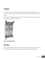
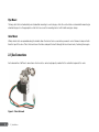
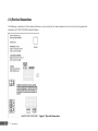
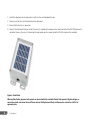
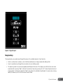
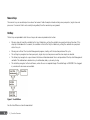
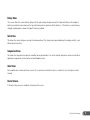
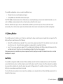
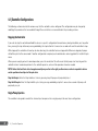
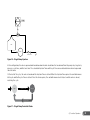
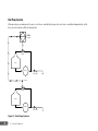
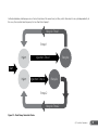
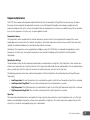
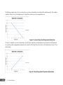
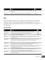
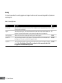
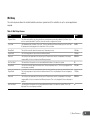
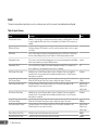
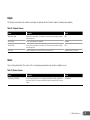
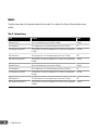
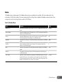
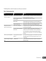
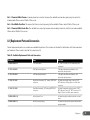
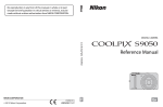
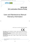
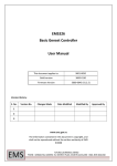
PC180 USER MANUAL
CHEMICAL MANAGEMENT SYSTEM
The PC180 Chemical Management System (CMS) is an electronic
control and monitoring system designed to augment chemical
injection pumps found in oil and gas fields. This system helps
reduce the amount of waste during the chemical injection
process. The PC180 calculates and manages an optimal chemical
injection cycle for the desired injection rate.
1 | Introduction............................................................................................................................................2
1.1 | Purpose.............................................................................................................................. 3
1.2 | Overview............................................................................................................................ 3
2 | Installation..............................................................................................................................................4
2.1 | Mounting........................................................................................................................... 5
2.2 | Gas Connections............................................................................................................... 6
2.3 | Grounding......................................................................................................................... 7
2.4 | Electrical Connections...................................................................................................... 8
3 | Controller Overview............................................................................................................................12
3.1 | Start Up........................................................................................................................... 13
3.2 | Display............................................................................................................................. 13
3.3 | Keypad............................................................................................................................. 14
3.4 | Home Screen................................................................................................................... 17
3.5 | Status Screens................................................................................................................ 18
4 | Controller Operation...........................................................................................................................20
4.1 | Battery Monitor.............................................................................................................. 21
4.2 | Controller Configurations.............................................................................................. 22
5 | Menu Reference..................................................................................................................................29
5.1 | Hot Key Menus................................................................................................................ 30
5.2 | Install Menu.................................................................................................................... 32
6 | Modbus Communications .................................................................................................................40
7 | Troubleshooting...................................................................................................................................42
8 | Support..................................................................................................................................................44
8.1 | Software Upgrade.......................................................................................................... 45
8.2 | Replacement Parts and Accessories.............................................................................. 47
8.3 | Technical Support........................................................................................................... 48
9 | Acronyms..............................................................................................................................................50
Approvals: Class I, Division I, Groups C and D; Class I, Zone 0, Ex/AEx ia [ia] IIB
#248705
1 | Introduction
1.1 | Purpose
This manual is intended to provide all of the information required to set up and operate the PC180 Chemical Management System.
It also covers basic troubleshooting techniques and support information.
Assumptions
The following assumptions have been made when writing this manual:
• The reader has some knowledge of the operation of a oil/gas well.
• A controller or installed simulator is available as a reference while reading this manual.
1.2 | Overview
The PC180 Chemical Management System is designed to control the amount of chemical being injected by a conventional chemical
injection pump.
In addition, the controller can be accessed remotely using the provided Modbus compatible RS485 communications port.
1 | Introduction
3
2 | Installation
2.1 | Mounting
Each controller is supplied with a universal mounting bracket. This bracket is designed to keep the controller away from other
surfaces so that the vent can be properly routed. As well, it provides a number of different mounting configurations to meet any
application.
Mount the bracket to the desired surface securely and then attach the controller to the bracket. Studs have been pre-pressed into
the four corners to make attaching the controller simple.
Figure 1 - Universal Mounting Bracket
Wall/Stud Mount
The universal mounting bracket includes nine holes that can be used for mounting to a wall or stud. To mount to a vertical stud, use
three of the vertically aligned holes. For mounting to a horizontal stud, use one of the three horizontally aligned holes.
2 | Installation
5
Pipe Mount
The long slots that run horizontally are intended for mounting to a vertical pipe, while the vertical slots are intended for mounting to
a horizontal pipe. Use the appropriate set of slots to secure the mounting bracket with U-bolts and pipe clamps.
Valve Mount
Wider, shorter slots are provided along the bend to allow the bracket to be secured to a pneumatic valve. Remove 2 adjacent bolts
from the top of the valve. Place the bracket over the holes and push the bolts through the bracket and valve, fastening them again.
2.2 | Gas Connections
Each solenoid has 3 different connections which must be connected properly in order for the controller to operate the valve.
Figure 2 - Valve Solenoid
6
2 | Installation
Supply
The supply side of the solenoid can be identified by the “IN” marking that is stamped on the body. A 90 degree elbow has been
pre-installed to make it easier to terminate in the field.
Clean supply gas must be supplied in order to operate the valve. The solenoid is designed to work up to 60 psi, but will operate at
lower pressures.
Dual valve assemblies are constructed so that the supply ports of the two solenoids are facing towards each other and are attached
with a tee. Although two separate solenoids will perform the same function, a single supply connection makes installation simpler.
Valve
The valve side of the solenoid can be identified by the “CYL” marking that is stamped on the body. A 90 degree elbow has been
pre-installed to make it easier to terminate in the field.
Vent
The vent faces towards the back of the enclosure and is threaded so that the appropriate fittings can be attached. The vent should
be routed according to the appropriate local regulations.
2.3 | Grounding
The controller is designed so that the circuit board is isolated from the enclosure and mounting hardware. This allows stray voltages
to be routed away from the electronics through a ground point. If connected correctly, there is less chance of damage to the
controller in the event of an electrical disruption.
A ground lug is provided on the bottom left corner of the enclosure. It is designed to fit up to 4 AWG wire. The enclosure should be
grounded according to the appropriate local regulations.
2 | Installation
7
2.4 | Electrical Connections
The following is an outline of the locations that devices can be wired to. All connected devices must meet the entity parameters
found in the ET-12001-1012-0000 Control Drawing.
Figure 3 - Physical Connections
8
2 | Installation
The PC180 is limited to a maximum of 2 solenoids and has support for a Line Pressure (LP) and Modbus Communications (COM1).
The PAS connection is not currently used.
The following table outlines all of the available connections.
Table 1 - Electrical Connections Summary
Location
Devices To Connect
Description
Solar
Solar Panel
Use only a 1.1 W Profire Solar Panel
Battery
6 V Battery
Use only a 6 V intrinsically safe Profire battery.
Sales Valve
Pump 1 Solenoid
Use only an intrinsically safe Profire approved solenoid.
Valve B
Pump 2 Solenoid
Use only an intrinsically safe Profire approved solenoid.
PAS
N/A
Not currently used.
LP
Line Pressure Switch/Sensor
Connect a 2 wire switch to COM/SIG or a 3 wire sensor to all three
connections to use line pressure features.
COM 1
Differential RS485 device
Modbus slave connection. Upgrade Port.
Battery
Each controller is shipped with the battery disconnected to save the life of the battery and ensure that the product has enough
energy to operate before requiring solar charge. Simply plug the pre-installed battery connector into the spot marked BATTERY. The
connector is not field replaceable as it requires a special tool. The battery should be plugged in before connecting the solar panel.
Warning: Only Profire approved batteries can be used with this controller. Protective components must never be bypassed
as it is unsafe to do so. Please refer to Replacement Parts and Accessories section for a full list of approved parts.
Solar Panel
The solar panel is optional, but will ensure that the battery is topped up and that operation of the controller is not interrupted due to
a low battery condition.
2 | Installation
9
1. Install the solar panel in a location where it will face the sun throughout the day.
2. Connect a pair of wires to the terminals on the solar panel.
3. Ensure that the battery is connected.
4. Connect the other end of the pair so that the minus (-) terminal on the solar panel is connected to the SOLAR COM input on the
controller. Likewise, the plus (+) terminal on the solar panel must be connected to the SOLAR + input on the controller.
Figure 4 - Solar Panel
Warning: Only Profire approved solar panels can be used with this controller. Panels that operate at higher voltages or
current are unsafe and cannot be used. Please refer to the Replacement Parts and Accessories section for a full list of
approved parts.
10
2 | Installation
Solenoids
Each solenoid is supplied with a pre-installed connector. The connector is not field replaceable as it requires a special tool.
Press each solenoid connector into one of Sales Valve or Valve B until you hear it click. Every solenoid is the same, so it does not
matter which one is plugged into a particular socket.
Warning: Only Profire approved solenoids can be used with this controller. Using any other solenoid or extending the
solenoid wires is unsafe. Please refer to the Replacement Parts and Accessories section for a full list of approved parts.
Pressure Inputs
Depending on the model, the controller comes with either one or two inputs. These inputs are physically the same and support
either two or three wire devices. Two wire devices only use the COM and SIG inputs, while three wire devices make use of the
PWR output as well.
The PWR output will provide a regulated 5 V output that is used to power the attached device. This output is only turned on for a
short duration while the sensor is being sampled, so measuring the power is not possible. As well, the SIG input is expecting to
see an input of 0.5 – 4.5 V, which is translated to the appropriate value by the controller.
It is recommended that you only use pressure devices recommended by Profire Energy to ensure the proper operation.
COM Ports
Each controller is equipped with one communications (COM) port. COM ports are designed to communicate with Modbus devices.
COM1 is disabled by default, but operates as a Modbus Slave when enabled. When enabled, all of the communication settings
for this port are made visible and can be configured by the installer. In general, the communication settings must be configured to
match the settings of the Modbus Master. This will allow the master to poll the controller as a slave to retrieve operational data. As
well, the master may also write data to the controller to change settings or to change the controller’s state.
Please refer to your local regulations to determine if an intrinsic safety barrier is required. This typically is the case if the
communications modem is located in a less hazardous area.
2 | Installation
11
3 | Controller Overview
3.1 | Start Up
On power up, the controller is initialized by performing the following operations:
• Load all previously saved values
• Close all valves
• Turn on the display
• Set the display to show the current controller state as the latest device status information.
The controller automatically enters the Inject state when powering up and begins counting down.
3.2 | Display
A Vacuum Fluorescent Display (VFD) is provided which consists of 2 lines x 16 characters. Each character is a 5x7 dot matrix with a
full underline bar. The display is partitioned into 2 areas with an unused column between them for spacing.
Figure 5 - Screen Layout
3 | Controller Overview
13
Menu Area
The content of the Menu Area (2 x 10 characters) shows the current state of the controller on start up. This area will change based
on user keypad interaction. The current state information as well as the setup menu is available in this area.
Status Area
The Status Area (2 x 5 characters) constantly rotates through all enabled inputs and outputs. By default, this includes the battery
voltage as well as the state of the Sales Valve. As other options are enabled on the controller, additional information becomes
available in this same area. For example, Valve B will be displayed if it has been enabled. If pressure devices such as line pressure
and tank pressure are enabled, their current value will also be displayed.
Automatic Shut Off
To conserve power, the display will automatically go to sleep if a key press has not been detected in the previous 30 seconds. This
time can be modified by the user.
Automatic Log Out
If security is enabled, the active user will be automatically logged out if a key press has not been detected in the previous 10
minutes. This time can be modified by the user.
3.3 | Keypad
An integrated keypad is included which allows the user to change settings, navigate through history, and control injection rates.
The navigation and numeric keys are overlapped to provide both sets of functionality on fewer keys. The controller automatically
knows what function to use based on the current controller display. When in the menus, the arrow keys are used. When editing a
numeric screen, the same keys are interpreted as their numerical equivalent.
14
3 | Controller Overview
Figure 6 – Keypad Layout
Navigation Keys
The navigation keys are used to move through the menus in the controller and select items from lists.
• Select is used to enter a sub-menu, select a field to be edited, or save changes made while editing a field.
• Cancel is used to back up through the menu levels or to cancel editing a value.
• The arrow keys allow the user to move up/down and left/right in the menu. If the display is on a line that has a sub menu
associated with it, pressing “Right” will enter the sub menu. Conversely, pressing the “Left” arrow will go back one level
of menu depth. If a field can be edited the “Right” arrow will put the controller into edit mode. If a numeric value is being
edited, the arrow keys will act as their numeric value instead.
3 | Controller Overview
15
Numeric Keys
The numeric keys are used to input new values for numeric fields. Examples include entering new pump rates, target rates and
pressures. If a numeric field is not currently being edited, then the number keys are ignored.
Hot Keys
The hot keys are provided to take the user to special menus or provide instant action.
• Pressing stop will send the controller to the Inject Hold state, putting the controller in a perpetual state of injection. If the
stop key is held down for 3 seconds, the controller will enter the Recycle Hold state, putting the controller in a perpetual
state of recycle.
• Pressing run will start the Injection Management program, starting with the injection portion of the cycle.
• The settings key navigates to where pump rate, target rate, injection pressure and fine tune inputs are located.
• The history key navigates to a special menu that shows information about the recent operation of the Injection Management
controller. This information is broken into cycle information, daily cycle and cycle log.
• The install key navigates to the install menu, where the user is required to login. The default login is 000-0000. Once logged
in, a number of sub menus are available.
Figure 7 - Install Menu
See the Install Menu section for more detail.
16
3 | Controller Overview
3.4 | Home Screen
As soon as the controller powers on, if the user presses stop/run, or if the user presses cancel to back out of the menus, the home
screen will appear on the display. By default, this shows the current state of the controller and the time remaining until it switches
state. As well, there are a number of screens available at this same level that show more detailed information.
Figure 8 – Home Screen Structure
Scrolling down from the home screen will take you through a number of other screens. Information such as the cycle type, start
time, and the current date/time are displayed here. Pressing select or the right arrow will take you to a screen that allows you to
force the controller to change states.
Current State
This screen is shown by default when the controller is powered up. It shows the current part of the cycle that the controller and a
timer that indicates when the state will change.
Cycle Information
This screen shows the information for the last cycle. This includes the type of cycle (Ok, Low Battery, Operator, etc…) as well as
the time that the cycle started.
3 | Controller Overview
17
Current Date/Time
This screen simply shows the current date and time. If this information is incorrect, the user must login and change the date and
time in the Date/Time menu. The date and time is reset back to January 1, 2000 when the battery is disconnected.
Change State
The controller can be manually forced into the Inject or Recycle state by performing a manual state change. The controller will enter
the selected state for a length of time (up to 200 days) set by the user in this screen. This will perform the same operation on all
pumps. Once the timer expires, the controller will go back to Inject and resume normal operation.
3.5 | Status Screens
When active, the display will automatically update the status area on the right hand side of the display. The information shown is a
summary of the current operation of the controller.
Figure 9 - Status Screens
18
3 | Controller Overview
Battery Status
This screen shows the current battery voltage with the solar charger disconnected so that it does not influence the reading. A
battery level indicator is also shown in the top right hand corner to show how full the battery is. If the battery is currently being
charged, a lightning bolt is shown instead of the battery indicator.
Solar Status
This shows the current voltage as seen on the solar panel input. The charger is disconnected during this reading so that it is not
influenced by the battery.
Temperature Status
This shows the temperature used by the controller for any optimization. It can be the internal temperature sensor with an offset
applied or a temperature written from an external Modbus master.
Valve Status
Each enabled valve is shown on these screens. The screen shows whether the valve is currently set to recycle (open) or inject
(closed).
Device Statuses
If the tank or line pressure is enabled it is shown on this screen.
3 | Controller Overview
19
4 | Controller Operation
The controller configuration can be accessed in two different ways:
• Through the menu using the display and keypad
• Using Modbus over the RS485 communications port.
The PC180 Modbus Communications User’s Guide discusses everything from physical connection to data format and access. As
such, the Modbus communications interface will not be discussed further in this manual.
When the controller starts up, all valves are closed and the controller is put into the Inject state. The injection timer starts
decrementing. Once this timer has expired, the controller decides what action to take based on the controller configuration.
4.1 | Battery Monitor
The controller samples the battery every 10 minutes, monitoring the voltage in order to prevent unpredictable valve operation. The
battery voltage is reported as one of the following:
• Normal: The controller behaves normally. If 6 successive battery samples are below 5.5 V, the controller closes all valves and
enters the Low state. A low battery alarm condition is recorded, which is reported in the history.
• Low: If 6 successive samples are above 6.0 V, the controller enters the Normal state. When entering the Normal state, the
controller will restart to the Close state for a duration specified by the Close Time parameter.
During power on or reset, and before any valves are opened, the battery voltage is sampled. The Normal or Low state is entered
based upon this sample.
Low Battery
The controller is designed to handle a number of failure conditions, most of which have already been discussed. If the controller
senses that the battery is low, it will take action to ensure that the valve(s) are left in a known state. When a low battery condition
has occurred, the controller will actuate the valve(s) and go into the Stopped state. The controller will remain in this state until the
battery has recovered or an operator has intervened.
The state that the valve is placed in when a low battery condition occurs is based on the Low Battery Fail Mode parameter that is
found in the Alarms menu.
4 | Controller Operation
21
4.2 | Controller Configurations
The following sections describe the various ways that the controller can be configured. The configuration may be changed by
modifying the parameters that are available through the user interface screens outlined in the preceding sections.
Stopping the Controller
If you wish to stop the controller and hold the valves in a specific configuration for maintenance, during installation, or at any other
time, pressing the stop button or pressing and holding the stop button for 3 consecutive seconds will send the controller to stop.
While stopped, the controller will count up to show how long the controller has been stopped for. Whenever stopped, all pumps
will both be put into the same mode. If another configuration is required, each enabled valve can be toggled in the Install>Outputs
menu.
When you are ready to go back to normal operation, press the run button. This will ensure that all pumps start injecting and the
controller returns to normal operation. As the controller operates, valves will be opened or closed as needed.
NOTE: Valves that had their state changed manually may not be in the right position since a valve is expected to be in a
certain position when Inject or Recycle starts.
Stop Hold Inject: Enter the Stop Hold Inject state by pressing stop. All pumps will perpetually inject.
Stop Hold Recycle: Enter the Stop Hold Recycle state by pressing and holding stop for 3 consecutive seconds. All pumps will
perpetually recycle.
Single Pump Injection
The controller is designed to control the chemical injection process for a single pump in the most basic configuration.
22
4 | Controller Operation
PC180
Controller
Valve
Tank
Pump
Check Valve
Figure 10 – Single Pump Injection
In this configuration, the valve is opened and closed based on internal calculations that are derived from the pump rate, target rate,
pressure, cycle time, and fine tune time. The calculated Injection Time and Recycle Time are used to determine when to open and
close the valve.
At the start of the cycle, the valve is closed and the Injection Time is started. When the Injection Time expires the controller moves
to Recycle and the Recycle Time is started. Once this timer expires, the controller moves back to Inject and the valve is closed,
restarting the cycle.
Start
Inject
Injection Time
Recycle
Recycle Time
Figure 11 – Single Pump Controller States
4 | Controller Operation
23
Dual Pump Injection
When operating a second pump, the same cycle time is used for both pumps, but each valve is controlled independently so that
they can each maintain a different desired rate.
PC180
Controller
Valve A
Tank 1
Pump 1
Check Valve
Valve A
Valve B
Tank 2
Pump 2
Check Valve
Figure 12 – Dual Pump Injection
24
4 | Controller Operation
As illustrated below, both pumps are set to start injection at the same time, but they switch from inject to recycle independently. In
this case, the injection time for pump 2 is less than that of pump 1.
Recycle Time 1
Pump 1
Injection Time 1
Inject
Recycle
Start
Inject
Injection Time 2
Recycle
Pump 2
Recycle Time 2
Figure 13 – Dual Pump Controller States
4 | Controller Operation
25
Perpetual Inject
Press the stop button and the controller will stop operation until the run button is pressed. The controller is configured to inject by
default when the controller is stopped. The counter on the screen shows how long the controller has been stopped.
Perpetual Recycle
The controller can also be stopped in a perpetual state of recycle. To achieve this, press and hold the stop button for 3 seconds. The
controller is still stopped and a counter on the screen indicates the time it has been stopped for, but the pump is set to perpetually
recycle.
Pump Actuation Sensor (PAS)
The PAS switch is used to keep a count of the number of pump actuations (the number of strokes the pump has made). The
controller increments the count each time it detects a switchtrip from the PAS. The count is used to update the cycle log with
the total number of actuations that occurred during each cycle. And, it is used to update the daily logs with the total number of
actuations that occurred over the day.
Line Pressure
The well may be equipped with a line pressure switch or sensor. This device simply allows for the monitoring and reporting of line
pressure so that it can be watched or trended to ensure that the pump is in fact pushing chemical into process.
Tank pressure
The well may be equipped with a tank pressure switch or sensor. This device simply allows for the monitoring and reporting of tank
pressure so that it can be watched or trended.
26
4 | Controller Operation
Temperature Optimization
The PC180 has an advanced temperature optimization feature that will auto adjust the Target Rate for a given pump. This allows
the pump rate to be automatically adjusted for chemicals such as Methanol that should be injected more regularly when the
temperature drops or that can be cut back or turned off when the temperature rises. There are two different ways for the controller
to access the temperature. In either case, the same algorithm is used.
Temperature Source
The temperature can be acquired from the internal temperature sensor. An offset can be applied to this reading if the current
reading does not accurately reflect the ambient temperature. The internal temperature sensor can have an offset that varies from
controller to controller and does not account for heating inside the enclosure.
Alternatively, the temperature can be acquired from a Modbus register. The SCADA host is responsible for populating a current
temperature. In either case, the resultant temperature is then used for the looking up the Target Rate in the Temperature
Optimization.
Optimization Settings
The optimization settings for the temperature optimization are used to define a straight line. This straight line is then used to cross
reference any temperature to a target injection rate. If the temperature falls outside the low and high points, the low and high target
rates are used respectively. The target rate can never exceed the pump rate, nor can it be less than zero.
The following parameters show how to define the end points of this line that defines the relationship between Target Rate and
Temperature.
• Low Temperature: The Low Temperature is the used to define a point at which the Low Temperature Target Rate is achieved.
• Low Temperature Target Rate: This rate will be achieved when the Low Temperature is reached.
• High Temperature: The High Temperature is used to define the point at which the High Temperature Target Rate is achieved.
• High Temperature Target Rate: This rate will be achieved when the High Temperature is reached.
Operation
The temperature optimization feature auto adjusts the target injection rate based on the current temperature each cycle. The high
and low rate and high/low temperature settings are used to define a straight line. The current temperature reading is taken at the
start of the cycle and the corresponding target rate is determined.
4 | Controller Operation
27
The following example shows the case where there is an inverse relationship between Target Rate and Temperature. This would be
used for a chemical such as Methanol where the Target Rate will decrease as the temperature rises.
Figure 14 - Inversely Proportional Temperature Optimization
Of course, the opposite case may be desirable as well. By simply changing the relationship between Target Rate and Temperature,
we can obtain a directly proportional relationship. This means that the Target Rate will increase as the Temperature increases. This is
shown below.
Figure 15 - Directly Proportional Temperature Optimization
28
4 | Controller Operation
5 | Menu Reference
5.1 | Hot Key Menus
The following menus are available to the operator without logging in. Simply press the corresponding hot key to access the menus.
Settings Menu
The settings hot key navigates to a special menu that contains all of the settings that are used by the controller. These parameters
are used to calculate the injection and recycle timers which in turn are used to control the opening or closing of the bypass valve.
These settings give the installer/operator control over how the well behaves. The following is a list of the settings that are available
in this menu:
Table 2 - Settings Screens
30
Screen
Description
Default Value
Pump Rate1
This tells the controller what the current rate of the pump is set to.
2.0 L/day
Target Rate1
This is the target rate of injection that should be achieved.
1.0 L/day
Pressure1
This is the process pressure at the injection point. The pressure is used to compensate for the super
compressibility of injection chemicals at different pressures.
5000 kPa
Fine Tune Time1
This time allows the operator to set some additional build time to fine tune the system
0s
Pump Rate2
This tells the controller what the current rate of the second pump is set to. (This is only displayed if the
second pump is enabled.)
2.0 L/day
Target Rate2
This is the target rate of injection that should be achieved. (This is only displayed if the second pump is
enabled.)
1.0 L/day
Pressure2
This is the process pressure at the injection point. The pressure is used to compensate for the super
compressibility of injection chemicals at different pressures. (This is only displayed if the second pump
is enabled.)
5000 kPa
Fine Tune Time2
This time allows the operator to set some additional build time to fine tune the system. This is only
displayed if the second pump is enabled.
0s
5 | Menu Reference
History Menu
Cycle Log
The cycle log is a history of each cycle that the controller goes through. A log entry is written at the end of a cycle, which is defined
as the point when the controller finishes the Inject Time. Therefore, the controller will write the first cycle log entry after the
controller starts and the initial Inject Time expires. Each log entry is stored in persistent memory so that it is maintained through any
power disruptions. A maximum of 25 log entries will be saved. Once this limit is reached, new entries are written over top of the
oldest entry.
The following information is saved for each cycle:
Table 3 - Cycle Log Screens
Screen
Description
Number of Cycles
The total number of cycles currently stored in the Cycle Log.
Cycle Type and Start Time
This screen shows the type of cycle that occurred as well as the date and time that the cycle
started. The cycle type will be one of: Current Cycle,Normal,Low Battery Shutdown,Operator
Change,Startup
Recycle Duration
This value shows the time that the pump was recycling.
Inject Duration
This value shows the time that the pump was injecting.
Number of Pump Actuations
The number of pump actuations that occurred during this cycle.
Reset Log
This clears all of the cycle log data.
Daily
The controller maintains daily production statistics which are written to persistent memory when the current time-of-day passes
the Day Start parameter. The following information is available in the Daily History menu:
5 | Menu Reference
31
Table 4 – Daily History Screens
Screen
Description
Date and Total Cycles
Shows the date for the given history record as well as the total number of cycles that occurred during that day.
Recycle/Inject
Displays the total time that the pump has been recycling and injecting
Time
For the day.
Number of Pump Actuations
Displays the number of pump actuations that occurred during the day.
Cycle Counts
There are a number of screens that are used to display all of the cycle types for the current day.
Day Start
This defines the gas day cut off. When the controller passes this time each day, the history for the current day
will stop and a new day will start.
Reset Log
This clears all of the daily log data.
5.2 | Install Menu
If security has been enabled, users must log in here in order to see the menus below. The install menu is entered by pressing the
install hot key. The default login is 000-0000, which can be changed in the security menu.
Date/Time
This menu allows the date and time to be configured. There is also a screen that allows daylight savings time to be enabled. The
following is list of all of the available screens:
Table 5 - Date/Time Screens
32
Screen
Description
Default
Date
Allows the user to set the current date.
Jan 1, 2000
Day Confirm
This confirms the current day of the week when the date is set.
N/A
5 | Menu Reference
Screen
Description
Default
Time
Allows the user to set the current time. Please note that this is in 24 hr time (i.e. 1:00 pm is
entered as 13:00)
00:00
DST Enable
If enabled, the controller will automatically adjust 2 times a year for daylight savings.
disabled
System
The System menu provides information specific to the given controller. This includes information such as the serial number and
firmware version. Features can be enabled, the display brightness can be adjusted, and the controller settings can be reset to
factory defaults. If any errors have been reported by the controller, they can be found at the end of this menu. The following is a list
of the available screens:
Table 6 - System Screens
Screen
Description
Default
Display Level
Sets the screen brightness. Can be used to save power or adapt to different lighting conditions.
50%
Display Auto Off
This sets the amount of time after the last key press that the display will stay on.
1m00s
Units
Set the controller to use imperial or metric units.
Metric
Serial Number
The serial number of the controller. This is required if features need to be enabled on the controller or it
is to be returned for repair.
N/A
Software Version
This identifies the specific firmware version that is currently running on the controller. This is required
if issues are reported to Profire. Please refer to the release notes for this version to see a list of known
issues.
N/A
Hardware Version
Shows the current version of hardware. This is used to manage different generations of hardware. It also
helps troubleshoot any future issues that may be linked to a specific version of hardware.
N/A
Restore Defaults
This will reset all controller settings back to the factory defaults. The user will be prompted to confirm
this action before the settings are restored.
No
Error Log
This screen will only appear if a detectable error has occurred. Some errors will result in the controller
restarting. This is the first place that should be checked if the controller is restarting itself.
N/A
Reset Error Log
If there are entries in the error log this screen will appear. It allows you to clear the error log. You will be
prompted to confirm this action.
No
5 | Menu Reference
33
Security
The Security menu allows the currently logged in user to logout. Installers are able to view and change both the Operator and
Installer login IDs.
Table 7 - Security Screens
34
Screen
Description
Default
Secure Login
Allows the installer to add security to the menu. If this is disabled, no login is requested and none of the
following screens are displayed.
Disabled
Logout
This screen forces a log out. The screen will move back to the main status screen when the operator has
logged out. The operator will be required to enter a password to regain entry to the Setup menu.
N/A
Auto Logout Time
The amount of time after the last key press that the user will remain logged in.
10m00s
Operator ID
This screen allows the Installer to set an Operator ID. This allows another user to have limited access to
the Setup menu. This screen is only visible to a logged in Installer.
000-0000
Installer ID
This screen allows the Installer to change the current Installer ID. This screen is only visible to a logged in
Installer. Note: If the Installer and Operator IDs are configured to be the same number, the user will
be logged in as the Installer when using this code.
000-0000
5 | Menu Reference
Well Setup
The well setup menu allows the installer to define some basic parameters of the controller set up if a custom application is
required.
Table 8 – Well Setup Screens
Screen
Description
Default
Program Mode
This allows an installer to set the controller run in an automatic mode with a default Cycle Time. If you
wish to override the default Cycle Time, then this must be configured as Custom.
Auto
Cycle Time
This determines the total time of the cycle. The Inject and Recycle Times will add up to the Cycle Time.
All pumps start injecting again at the completion of this cycle time.
2m00s
Pump Rate1
This tells the controller what the current rate of the pump is set to.
2.0 L/day
Target Rate1
This is the target rate of injection that should be achieved.
1.0 L/day
Pressure1
This is the process pressure at the injection point. The pressure is used to compensate for the super
compressibility of injection chemicals at different pressures.
5000 kPa
Fine Tune Time1
This time allows the operator to set some additional build time to fine tune the system
0s
Pump Rate2
This tells the controller what the current rate of the second pump is set to. (This is only displayed if the
second pump is enabled.)
2.0 L/day
Target Rate2
This is the target rate of injection that should be achieved. (This is only displayed if the second pump is
enabled.)
1.0 L/day
Pressure2
This is the process pressure at the injection point. The pressure is used to compensate for the super
compressibility of injection chemicals at different pressures. This is only displayed if the second pump is
enabled.
5000 kPa
Fine Tune Time2
This time allows the operator to set some additional build time to fine tune the system. (This is only
displayed if the second pump is enabled.)
0s
5 | Menu Reference
35
Inputs
The inputs menu allows input devices such as a line pressure switch or sensor to be enabled and configured.
Table 9 - Inputs Screens
36
Screen
Description
Pump Actuation Sensor
Enabled = The controller is counting switch trips that it detects on the PAS switch. The count
is used to update the PAS entries in the cycle and daily logs. Disabled = PAS counter is not
enabled.
PAS Switch Polarity
Configures the type of PAS switch to use. The controller can detect a trip on a close or open
of a switch.
PAS Monitor
Inject = Switch trips are only being counted during the inject cycle. Recycle = Switch trips
are only counted during the recycle cyle. Always on: Switch trips are always counted.
Temperature Source
This is used to select the internal temperature source or use the temperature from Modbus,
which must be written by an external Modbus master.
Internal
Temperature Offset
This is an offset that is applied to the internal temperature reading. This is required if the
factory calibration of the temperature sensor was not completed.
0C
Tank Pressure Device Type
Enables the use of a Tank Pressure Switch or Sensor. Disabled = Device not installed or
unused. Switch = Discrete Input Switch installed and enabled. Sensor = A Tank Pressure
Analog Sensor is installed.
Disabled
Tank Pressure Range
When the Tank Pressure Device Type is sensor, defines the range of the sensor.
5.0 psi
Tank Pressure Switch Polarity
Configures the type of Tank Pressure switch to use. The controller can detect a Tank
Pressure trip on a close or open of a switch.
Normally Open
(Detects on a
switch close)
Line Pressure Device Type
Enables the use of a Line Pressure Switch or Sensor. Disabled = Device not installed or
unused. Switch = Discrete Input Switch installed and enabled. Sensor = A Line Pressure
Analog Sensor is installed.
Disabled
Line Pressure Range
When the Line Pressure Device Type is sensor, defines the range of the sensor.
500.0 psi
Line Pressure Switch Polarity
Configures the type of Line Pressure switch to use. The controller can detect a Line
Pressure trip on a close or open of a switch.
Normally Open
(Detects on a
switch close)
Pressure Sensor Scan Time
Defines the rate at which all pressure sensors are read.
00m01s
Pressure Switch Scan Time
Defines the rate at which all pressure switches are read.
00m01s
5 | Menu Reference
Default
Outputs
The Outputs menu allows the installer to configure the behavior of Valve B which enables the dual pump capability.
Table 10 - Outputs Screens
Screen
Description
Default
Sales Valve State
Shows the current state of the valve. The user can also manually override
the valve position.
N/A
Valve B Type
Allows a 2nd pump to be enabled.
Disabled
Valve B State
Shows the current state of the valve. The user can also manually override
the valve position.
N/A
LP Power
Sets the operation to use the LP Power connection for.
Default (Power a LP sensor)
Alarms
These settings determine if the valve is left in a closed or open position when an alarm condition occurs.
Table 11 | Alarms Screens
Screen
Description
Default
Low Battery Fail Mode
This screen allows the user to configure the behaviour of the controller for
this type of failure. The user can decide to have the controller fail Closed or
Open.
Closed/Inject
5 | Menu Reference
37
Optimize
The optimize menu allows the temperature optimization to be enable. Once enabled, the settings for the optimization become
available.
Table 12 - Optimize Screens
38
Screen
Description
Default
Optimization Type 1
Allows the optimization type to be selected for Pump 1.
Disabled
Low Temperature 1
The low temperature to use the min/max target injection rate for Pump 1.
0C
Low Temperature Target Rate 1
The Target Rate to use when the temperature is at or below the low temperature
for Pump 1.
2.0 L/day
High Temperature 1
The high temperature to use the min/max target injection rate for Pump 1.
40 C
High Temperature Target Rate 1
The Target Rate to use when the temperature is at or above the high temperature
for Pump 1.
1.0 L/day
Optimization Type 2
Allows the optimization type to be selected for Pump 2.
Disabled
Low Temperature 2
The low temperature to use the min/max target injection rate for Pump 2.
0C
Low Temperature Target Rate 2
The Target Rate to use when the temperature is at or below the low temperature
for Pump 2.
2.0 L/day
High Temperature 2
The high temperature to use the min/max target injection rate for Pump 2.
40 C
High Temperature Target Rate 2
The Target Rate to use when the temperature is at or above the high temperature
for Pump 2.
1.0 L/day
5 | Menu Reference
Modbus
The Modbus menu will only appear if the Modbus feature has been enabled on the controller. This feature allows data to be
retrieved by a SCADA host remotely. This menu contains all of the settings that are available for Modbus communications. These
settings must match the settings that are used in the SCADA host.
Table 13 | Modbus Menus
Screen
Description
Default
Modbus Port
Sets whether the Modbus port is active or not on. It is disabled by default to save
power.
disabled
Station Address
Defines the Modbus station. Valid values are 1 to 247. This setting must match the
settings on your Modbus master.
1
Protocol
The specific Modbus protocol that is use. This can be set to either RTU or ASCII.
This setting must match the settings on your Modbus master.
RTU
Baud Rate
The speed of the serial port. This setting must match the settings on your Modbus
master.
9600
Data Bits
Sets the number of data bits in each character. This setting must match the
settings on your Modbus master.
8
Parity
The parity of the character. This setting must match the settings on your Modbus
master.
None
Stop Bits
The number of stop bits per character. This setting must match the settings on
your Modbus master.
1
Time Format
Specifies how time and dates are represented in the Modbus registers. Seconds
format will utilize one or more registers to show elapsed seconds. H:M:S format
allocates separate registers for Hours, Minutes, and Seconds. Please refer to the
Modbus Communications User’s Guide for more details.
seconds
5 | Menu Reference
39
6 | Modbus Communications
The controller is equipped with an RS-485 port which is designed primarily to provide communications to a SCADA system. This
port provides most of the functions available from the front panel user interface using the Modbus protocol. ThePC180 Modbus
Communications User’s Guide discusses the physical connections, communications settings, and the available registers.
6 | Modbus Communications
41
7 | Troubleshooting
The following outlines a number of common issues that may be encountered.
Table 14 - Troubleshooting Guide
Issue
Cause
Resolution
The display won’t come on when
the battery is plugged in.
The fuse is blown on the battery
Return to Profire Energy to be repaired. To avoid this issue, make sure to
avoid shorting the battery connections.
Battery is unplugged or there is a
loose connection
Plug in the battery and check all connections
Battery is dead
Charge the battery as per the directions on the side of the battery. If it
does not hold a charge, contact Profire Energy to purchase a new battery.
Software has been erased
Reprogram the software using the software upgrade procedure.
A key is stuck on the keypad
The keypad will need to be replaced. Please call Profire Energy to arrange
for the controller to be repaired.
The main core of the controller has
been shocked
The controller core must be replaced. Please call Profire Energy to
arrange for the controller to be repaired. To avoid this, always transport
the controller board in a static protection bag and avoid touching any
exposed connections along the back of the controller without appropriate
grounding.
Cannot Log in to the Setup Menu
You have forgotten your operator/
installer ID.
If the Operator ID has been forgotten, use the Installer ID. If the Installer
ID has been forgotten, Profire Energy can generate a new ID on a per
controller basis.
Controller is sitting in the stopped
state
The battery is low
Replace the battery and ensure that the solar panel is connected and
positioned correctly.
Pressing a button does not
produce the desired response.
7 | Trouble Shooting
43
8 | Support
8.1 | Software Upgrade
On occasion, software upgrades are made available. These releases will contain new features as well as resolutions to issues found
in the product. The release notes describe the changes that are available in each release. The new software can be downloaded
through the communications port whether the Modbus option is enabled or not.
It is recommended that the controller be removed from the well before the upgrade is performed as the valve operation cannot be
trusted during the upgrade.
Prerequisites
The following equipment is required to upgrade the controller:
• Battery
• Laptop with a USB port
• USB to RS485 converter
• Latest firmware file.
Setup
1. Ensure that the USB to RS485 adapter is configured in 2 wire mode.
2. Wire the RDA(-) to COM1 A and RDB(+) to COM1 B. The GND can be wired to the unlabeled connection on COM1 between A
and B, but is not necessary.
3. Plug adapter into an available USB port.
4. Install the drivers that were provided with the USB to RS485 converter
8 | Support
45
Upgrade Procedure
1. Hold the install button down
2. Plug the battery into the controller
3. Release the install button
4. If the controller does not enter the upgrade program, the previous software that was installed may not include this program.
Please contact Profire.
5. Follow the prompts on the screen to erase the current firmware. To abort the upgrade process at this point, unplug the battery.
• When prompted to do so, download the firmware
• Open the Upgrade Utility
• Browse to the latest file provided by Profire Energy.
• Select the appropriate COM port from the drop down list.
• Click the Connect button
• Select Download
6. The display on the controller should change to show the status of the download and a progress bar should appear on the
screen, showing how much code has been downloaded.
7. When the download is complete, the controller should start normally.
Upgrade Errors
During the download of a firmware image, errors may occasionally occur. If this does happen, simply repeat the procedure again,
making sure to erase the current firmware. If an error occurs multiple times in a row, contact Profire Energy.
The following is a list of errors that may be seen:
Err 1 – Invalid file format. The Bootloader found information in the serial stream that did not match the expected format. This could
be a transmission error or an error with the file.
Err 2 – Dropped Characters. While parsing the incoming stream, extra characters were detected. This typically means that some
data was lost.
46
8 | Support
Err 3 – Character Buffer Overrun. Incoming characters were lost because the controller was too busy processing to service the
incoming data. Please contact Profire if this occurs.
Err 4 – Flash Buffer Over Run. This means that there is a back log saving to the controller. Please contact Profire if this occurs.
Err 5 – Character Buffer Under Run. The controller was expecting to parse more incoming characters, but there are none available.
Please contact Profire if this occurs.
8.2 | Replacement Parts and Accessories
Several replacement parts or accessories are available for purchase. These items are listed in the table below with their associated
part numbers. Please contact sales for the current price list.
Table 15 - Available Replacement Parts and Accessories
Part Number
Name
Description
ET-00000-0000-0247
1.1 W Solar Panel
6V, 1.1W CSA Class 1 Div 2 Intrinsically safe
solar panel
ET-12001-1008-0001
5 Ah Replacement Battery
CSA approved replacement battery with
intrinsically safe protection.
ET-12001-1008-0002
8 Ah Replacement Battery
CSA approved replacement battery with
intrinsically safe protection.
ET-12000-1011-0001
Single Valve Assembly, 3/8” tubing, AMP-DUAC
connector
Includes a pneumatic valve solenoid, 2 3/8”
NPT elbows, an O Ring, Nylon Lock Nut and
connector.
ET-12000-1011-0002
Dual Valve Assembly, 3/8” tubing, AMP-DUAC
connector
Includes 2 pneumatic valve solenoids, 2 3/8”
NPT elbows, a Tee, a 3/8” NPT connector, 2 O
Rings, 2 Nylon Lock Nuts, and connectors.
ET-00000-0000-0230
Valve Solenoid Core
Includes the plastic molded solenoid core and
wires
ET-00000-0000-0231
Valve Piston and Spring
Includes the internal valve piston and attached
spring assembly
8 | Support
47
Part Number
Name
Description
ET-12000-1009-0003
Battery Bracket
Replacement bracket used to retain either
battery.
ET-00000-0000-0235
2 Pin Connector
2 Pin Weidmuller connector
ET-00000-0000-0236
3 Pin Connector
3 Pin Weidmuller connector
ET-00000-0000-0060
1/2“ Liquid Tight Knockout Seal
NEMA rated plug to prevent water and dust
from entering unused holes.
8.3 | Technical Support
Contacting Support
Support is available from Profire Energy.
Web
Please visit our website at http://www.profireenergy.com
Phone
Profire Energy support can be contacted via phone at our office in Spruce Grove, AB at 1-780-960-5278. Authorized distributors will
be provided information on how to contact someone outside the normal business hours listed above.
Identifying the Issue
Please take the time to identify the issue that is being experienced. Many issues can be resolved by simply upgrading the controller
to the latest software. If the issue still persists, please try and determine if there is an issue with the software or hardware. Here
are some common indications of each type of issue:
48
8 | Support
Hardware
• Battery is not charging
• Some display pixels do not power up
• The controller display does not come up and the controller does not draw any current
• A key is stuck
Firmware
• The controller restarts itself (goes back to close at an incorrect time)
• There are entries in the error log (Located in the System menu)
• Controller behaviour is erratic
• The same issue happens across multiple controllers
Reporting Software Issues
We strive to provide the best software possible that is free of defects. As with any controller, there may be issues. When issues do
arise, please do the following:
• Copy down any errors that are found in the error log
• Note the controller configuration
• Note what was being done on the controller when the issue occurred
• Note the serial number and version number of the controller that experienced the issue
• Detail instructions on how to repeat the issue if possible
Repair Process
Please contact Profire Energy and arrange to have the controller repaired. Please be ready to explain the issues that are being
experienced. A detailed account of the problem will be required so that the issue can be addressed in a timely fashion. Returned
controllers will take approximately 4 – 6 weeks to be diagnosed and repaired.
8 | Support
49
9 | Acronyms
Acronyms
Phrase
ADC
Analog-to-Digital Converter
AI
Analog Input
CVC
Configurable Valve Controller
DAC
Digital-to-Analog Converter
DI
Digital Input
DO
Digital Output
ESD
Emergency Shut Down
N/C
Normally Closed
N/O
Normally Open
PAS
Pump Actuations Sensor
PSI
Pounds per Square Inch
R
Read Permission
RTU
Remote Terminal Unit
R/W
Read/Write Permission
SCADA
Supervisory Control And Data Acquisition
V
Volts
VFD
Vacuum Fluorescent Display
VI
Virtual Input
9 | Acronyms
51
www.profireenergy.com
© 2014 PROFIRE